
Hardware Reference Guide - dc7700 CMT


Table Of Contents
- Product Features
- Hardware Upgrades
- Serviceability Features
- Warnings and Cautions
- Unlocking the Smart Cover Lock
- Removing the Computer Access Panel
- Replacing the Computer Access Panel
- Removing the Front Bezel
- Replacing the Front Bezel
- Removing Bezel Blanks
- Installing Additional Memory
- Removing or Installing an Expansion Card
- Drive Positions
- Removing a Drive from a Drive Bay
- Installing Additional Drives
- Changing from a Minitower to a Desktop Configuration
- Changing from a Desktop to a MinitowerConfiguration
- Specifications
- Battery Replacement
- External Security Devices
- Electrostatic Discharge
- Computer Operating Guidelines, Routine Care and Shipping Preparation
- Index
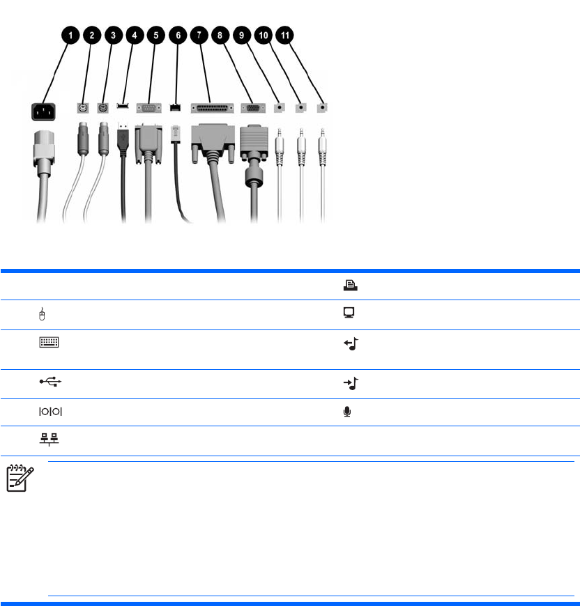
Rear Panel Components
Table 1-3 Rear Panel Components
1 Power Cord Connector 7 Parallel Connector
2 PS/2 Mouse Connector (green) 8 Monitor Connector
3 PS/2 Keyboard Connector (purple) 9 Line-Out Connector for powered audio
devices (green)
4 Universal Serial Bus (USB) 10 Line-In Audio Connector (blue)
5 Serial Connector 11 Microphone Connector (pink)
6 RJ-45 Network Connector
NOTE Arrangement and number of connectors may vary by model.
The monitor connector on the system board is inactive when a PCI Express graphics card is installed in the
computer.
If a PCI graphics card is installed, the connectors on the card and the system board may be used at the same
time. Some settings may need to be changed in Computer Setup to use both connectors. For information
about Boot Order, refer to the Computer Setup (F10) Utility Guide on the Documentation and Diagnostics
CD.
4 Chapter 1 Product Features ENWW