
Hardware Reference Guide - dc7700 CMT


Table Of Contents
- Product Features
- Hardware Upgrades
- Serviceability Features
- Warnings and Cautions
- Unlocking the Smart Cover Lock
- Removing the Computer Access Panel
- Replacing the Computer Access Panel
- Removing the Front Bezel
- Replacing the Front Bezel
- Removing Bezel Blanks
- Installing Additional Memory
- Removing or Installing an Expansion Card
- Drive Positions
- Removing a Drive from a Drive Bay
- Installing Additional Drives
- Changing from a Minitower to a Desktop Configuration
- Changing from a Desktop to a MinitowerConfiguration
- Specifications
- Battery Replacement
- External Security Devices
- Electrostatic Discharge
- Computer Operating Guidelines, Routine Care and Shipping Preparation
- Index
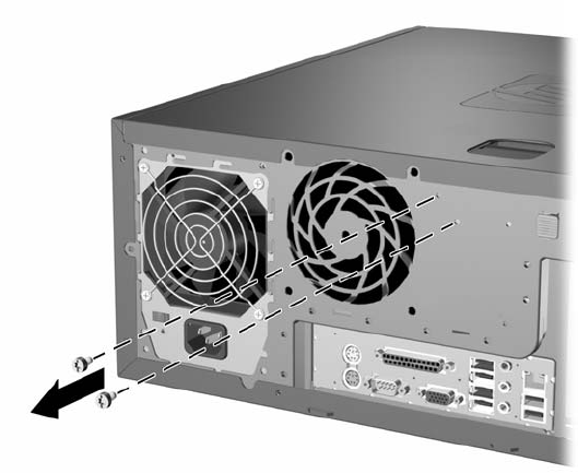
5. Use the Smart Cover FailSafe Key to remove the two tamper-proof screws that secure the Smart
Cover Lock to the chassis.
Figure 2-1 Removing the Smart Cover Lock Screws
6. Remove the access panel.
To reattach the Smart Cover Lock, secure the lock in place with the tamper-proof screws.
ENWW Unlocking the Smart Cover Lock 11