
User's Manual
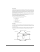
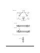
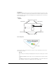
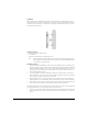
Table Of Contents

10
Ceiling Mount Procedure
1. If possible, remove the ceiling tile from its frame and place it, finished side down, on a work surface.
2. Mark a point on the upper or unfinished side of the tile where the light pipe extender will be installed. It is
best to leave at least 5 cm (2 in.) or more between the edge of the ceiling tile and the center of the light pipe
to allow clearance for placement of the Radio Port and antenna connections above the ceiling tile.
3. Drill two 6 mm (1/4 inch) holes adjacent to each other through the ceiling tile to accommodate the twin shafts
of the light pipe extender.
4. Snap the clips of the light pipe extender into the bottom of the Radio Port case.
5. Place the Radio Port and light pipe extender over the hole on the unfinished side of the ceiling tile . Fit the light
pipe extender through the hole to project through on the finished side of the ceiling tile.
6. Place the label for the light pipe badge over the hub on the back of the badge and press the badge onto the
light pipe extender from the finished side of the ceiling tile.
7. If required, install a safety wire, between 1.5mm (.06in.) and 2.5mm (.10in.) in diameter, to a secure, stationary
point in the ceiling space.
8. If required, attach a security cable to a secure, stationary point in the ceiling space.
9. Attach the appropriate antennas to the Radio Port's antenna connectors. If the antennas are intended to be
mounted below the ceiling tile, it may be convenient to make provision for this installation in the same ceiling
tile as the Radio Port and light pipe extender.
10. Bring the ceiling tile into the ceiling space.
11. Attach the end of the safety wire from Step 7. to the safety wire tie point on the Radio Port.
12. Attach the end of the security cable from Step 8. to the Radio Port's lock port located on one end of the Radio Port.
13. Plug the Ethernet cable into the Radio Port's RJ-45 port and to a switch with an 802.3af-compatible power
source.
14. Verify the Radio Port has power by observing the LEDs.
15. Place the ceiling tile back in its frame to complete the installation.
Supported Antennas
The following is a list of available antennas for the ProCurve Radio Port 220:
Diversity means that the antenna has two cables connecting it to the Radio Port 220. (Antenna J8997A has a diversity
feature). A 2.4 GHz diversity antenna will have one cable connecting to the "2.4 GHz Primary" connector, and the
second cable connecting to the connector labeled "2.4 GHz"; a 5 GHz diversity antenna will connect to the "5 GHz
Primary" and "5GHz" connectors. All of the other antennas have a single cable which would typically connect to either
the "2.4 GHz Primary" or "5GHz Primary" antenna connector as appropriate.
HP Product
Number
Frequency
Range (GHZ
Antenna Type/
Coverage
Diversity Actual Gain w/
specified cable
(dBi)
J8441A 2.4 Indoor/Outdoor
Omni-Directional
(dipole)
No 4.4
J8444A 2.4 Outdoor Omni-
directional (dipole)
No 7.4