
User's Manual
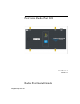
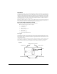
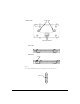
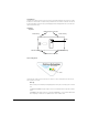
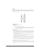
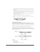
Table Of Contents

6
LED Indicators
The Radio Port 220 has LED indicators on the front of the case that visually display the status of the device. When
the Radio Port is mounted above a suspended ceiling, an additional set of LED indicators on the back of the unit can
be extended through the ceiling tile using a provided lightpipe extender, making the Radio Port location and status
visible from below the ceiling.
Wall Mount.
Above Ceiling Mount.
The LED indicators display connection status and error conditions, as well as network activity for each of the two
radios. Operation is as follows:
Start-up:
Radio Port Startup occurs immediately following the application of PoE power, or following a power or software
reset.
1.Both GREEN and AMBER LEDs light steadily for several seconds while the Radio Port performs an internal
self-test.
2.The AMBER LED then flashes 3 times per second, while the GREEN LED is off. This indicates that the Radio
Port is attempting to communicate to a compatible wireless services-enabled switch.
RSMA Antenna Connectors
2.4 Ghz Primary5 Ghz Primary
2.4 Ghz Secondary5 Ghz Secondary
RSMA Antenna Connectors
LEDs
Top View