
User's Manual
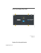
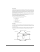
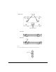
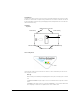
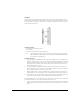
Table Of Contents

7
3.Both LEDs then go off for a moment, followed by both LEDs lighting steadily for a few seconds.
4.After this sequence, assuming no error conditions have occurred, the Radio Port will enter Normal operation
mode. This means that the Radio Port has successfully communicated with and been adopted by a wireless
services-enabled switch. If this startup sequence repeats itself, then it is likely that the Radio Port is unable to
contact a compatible wireless services -enabled switch, and the installer should review the Troubleshooting
section below.
Normal Operation:
Once the Radio Port has established a connection to a compatible wireless services-enabled switch the Radio
Port will begin normal operation. During normal operation, the GREEN LED indicates status of the 802.11 b/g
radio, and the AMBER LED indicates status of the 802.11a radio.
• Without Wireless Traffic: Each LED will briefly flash once every 5 seconds, to indicate that power is on,
and the Radio Port is communicating normally to its wireless services-enabled switch. The flashing may
not be synchronous between the two LED indicators.
• With Wireless Traffic: Each LED will briefly flash more frequently than once every 5 seconds, and in an
irregular fashion, to represent traffic on that radio.
Radio Error Mode:
• The GREEN LED flashes on and off steadily once per second if an error prevents the 802.11b/g radio from
operating normally.
• The AMBER LED flashes on and off steadily once per second if an error prevents the 802.11a radio from
operating normally.
Installation Instructions
The ProCurve Radio Port 220 can be mounted either on a wall or other mounting point, or above a suspended ceiling.
This Radio Port is not designed for mounting on a desk.
To prepare for installation, perform the following steps:
1. Review site survey and network analysis reports to determine the location and mounting position for the
ProCurve Radio Port 220. Verify the recommended external antenna type and antenna mounting configura-
tion.
2. Match the Radio Port model number on the purchase order with the model numbers in the packing list and on
the case of the device shipped.
3. Verify that the contents of the box include the intended ProCurve Radio Port 220 and mounting hardware:
4. Verify that you have the recommended external antenna model and type for the desired installation. External
antennas must be purchased separately. For a list of Supported Antennas for this Radio Port, see 'Supported
Antennas' below.
5. Connect a CAT-5 cable to a compatible 802.3af power source and run the cable to the installation site. Ensure
that there is sufficient slack on the cable to perform the installation steps.
Radio Port Item Notes
220 J9005A 802.11a & 802.11b/g radios with external connectors. This
radio port is configurated with two pairs of RSMA
connectors