Console Management Controller User Guide Second Edition (July 2001) Part Number 218258-002 Compaq Computer Corporation Compaq Confidential – Need to Know Required Writer: A. J. Scheckelhoff Project: Compaq Console Management Controller User Guide Comments: Part Number: 218258-002 File Name: a-frnt.
Notice © 2001 Compaq Computer Corporation Compaq, Compaq Insight Manager and the Compaq logo Registered in U.S. Patent and Trademark Office. Microsoft and Windows are trademarks of Microsoft Corporation in the United States and other countries. Intel is a trademark of Intel Corporation in the United States and other countries. Compaq shall not be liable for technical or editorial errors or omissions contained herein.
Contents About This Guide Text Conventions.......................................................................................................vii Symbols in Text....................................................................................................... viii Symbols on Equipment............................................................................................ viii Rack Stability .........................................................................................................
iv Compaq Console Management Controller User Guide Installation Procedures............................................................................................. 2-7 Installing the Standard Sensors ......................................................................... 2-8 Connecting the Cord Retention Bracket ......................................................... 2-17 Connecting the Sensors to the CMC ...............................................................
About This Guide Change Password Screen................................................................................ 4-11 Device Configuration............................................................................................. 4-12 CMC Properties Screen .................................................................................. 4-13 Sensor Setup Screen ....................................................................................... 4-15 Accessory Setup Screen......................
vi Compaq Console Management Controller User Guide Appendix B Electrostatic Discharge Grounding Methods .................................................................................................B-2 Appendix C Specifications Specifications...........................................................................................................C-2 Appendix D Pin Layout Configuration Compaq CMC ...................................................................................................
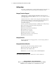
About This Guide This guide is designed to be used as step-by-step instructions for installation and as a reference for operation, troubleshooting, and future upgrades. Text Conventions This document uses the following conventions to distinguish elements of text: Keys Keys appear in boldface. A plus sign (+) between two keys indicates that they should be pressed simultaneously. USER INPUT User input appears in a different typeface and in uppercase. FILENAMES Filenames appear in uppercase italics.
viii Compaq Console Management Controller User Guide Symbols in Text These symbols may be found in the text of this guide. They have the following meanings. WARNING: Text set off in this manner indicates that failure to follow directions in the warning could result in bodily harm or loss of life. CAUTION: Text set off in this manner indicates that failure to follow directions could result in damage to equipment or loss of information.
About This Guide This symbol on an RJ-45 receptacle indicates a Network Interface Connection. WARNING: To reduce the risk of electric shock, fire, or damage to the equipment, do not plug telephone or telecommunications connectors into this receptacle. This symbol indicates the presence of a hot surface or hot component. If this surface is contacted, the potential for injury exists. WARNING: To reduce the risk of injury from a hot component, allow the surface to cool before touching.
x Compaq Console Management Controller User Guide Getting Help If you have a problem and have exhausted the information in this guide, you can get further information and other help in the following locations. Compaq Technical Support In North America, call the Compaq Technical Phone Support Center at 1 1-800-652-6672 (1-800-OK-COMPAQ) . This service is available 24 hours a day, 7 days a week. Outside North America, call the nearest Compaq Technical Support Phone Center.
Chapter 1 Overview This chapter contains information on the following topics: ■ Compaq Console Management Controller ■ General description ■ Standard CMC features ■ Front panel ■ Rear panel Compaq Confidential – Need to Know Required Writer: A. J. Scheckelhoff Project: Compaq Console Management Controller User Guide Comments: Part Number: 218258-002 File Name: b-ch1 Overview.
1-2 Compaq Console Management Controller User Guide Compaq Console Management Controller The Console Management Controller (CMC) offers one model, part number 203039-B21. This unit is rack-mountable and is Worldwide voltage adaptable. General Description The CMC is a rack-mounted device intended to monitor and control the environment within a single-rack or multiple-rack suites. The system consists of a CMC, several sensors, and the Compaq Intelligent Rack Manager Lite software.
Overview Standard CMC Features ■ 1U design ■ Ethernet communications port for data exchange with a host computer ■ Four analog inputs: G Two temperature inputs G One humidity input G One voltage monitor for AC mains ■ Two programmable fan output power controls ■ Eight discrete inputs G Four intrusion inputs G One smoke input G One mechanical shock/vibration input G Two Auxiliary (AUX) inputs ■ Two electronic door lock controls ■ Easy configuration via: G Compaq Intelligent Rack Ma
1-4 Compaq Console Management Controller User Guide Communications Ports The communications port for data exchange with the host computer consists of an Ethernet port (RJ-45) using SNMP communication. The serial communication port (RJ-11) allows for the use of a VT100/Xmodem device. Compaq Intelligent Rack Manager Lite With each CMC, Compaq supplies a CD containing Intelligent Rack Manager Lite software.
Overview Front Panel The CMC is rack-mountable in a 1U configuration. 1 2 3 4 5 6 8 9 10 7 Figure 1-1. Front panel configuration Table 1-1 CMC Front Panel Alarm LED Network LED Serial communication LED Serial communication port (RJ-11) Escape button Scroll up button Enter/Alarm silence button LCD display Power LED Power button Compaq Confidential – Need to Know Required Writer: A. J.
1-6 Compaq Console Management Controller User Guide Front Panel Controls The CMC front panel includes the controls required to: ■ Power the unit On or Off. ■ Scroll through LCD menus. ■ Select LCD menu items. ■ Silence audible alarms and deactivate alarm relays (if these features are enabled in the control software). NOTE: For information about changing the configuration on the CMC, or to check the current configuration, see Chapter 4, “Software.
Overview Rear Panel The CMC features the following rear panel configuration: 1 2 3 4 5 6 7 8 9 11 13 15 17 10 12 14 16 19 18 21 20 Figure 1-2. Rear panel configuration Compaq Confidential – Need to Know Required Writer: A. J. Scheckelhoff Project: Compaq Console Management Controller User Guide Comments: Part Number: 218258-002 File Name: b-ch1 Overview.
1-8 Compaq Console Management Controller User Guide Table 1-3 CMC Rear Panel Description Type of connector Main power input AC input (IEC 320-10A) Input voltage monitor / Power input for Fan #1 and #2 AC input (IEC 320-10A) Fan #1 Power output for fan #1 (IEC 320–10A) Fan #2 Power output for fan #2 (IEC 320–10A) Relay #1 Alarm relay (RJ-12) Relay #2 Alarm relay (RJ-12) Intrusion sensor #1 Discrete input (RJ-12) Intrusion sensor #2 Discrete input (RJ-12)
Chapter 2 Installation This chapter provides information on the following topics: ■ Installation requirements ■ Installation procedures ■ Powering on the CMC ■ Completing the installation Compaq Confidential – Need to Know Required Writer: A. J. Scheckelhoff Project: Compaq Console Management Controller User Guide Comments: Part Number: 218258-002 File Name: c-ch2 Installation.
2-2 Compaq Console Management Controller User Guide Installation Requirements This section lists items required to install the CMC. Items supplied with the basic CMC Kit The CMC Kit (Compaq Part Number 203039-B21) contains the following components: Hardware Figure 2-1.
Installation Input power cord (country-specific) Tie wraps Voltage monitor cord/fan input cord (country-specific) Screws, washers and cage nuts Serial communication cable (RJ-11 to DB-9) Intrusion sensors (2 sets) Sensor cable Double-sided tape Sensor cable Sensor cable Cord management clips Temperature sensor Cord retention bracket Software/Reference Material ■ Important Safety Information guide to be reviewed before installing this product ■ Power Products Documentation C
2-4 Compaq Console Management Controller User Guide Optional Sensor Kit, with assorted cable lengths Compaq Part Number 203039-B22 (sold separately) Figure 2-2. Optional sensor kit content Temperature sensor Sensor cable Sensor cable Sensor cable Sensor cable Humidity sensor Humidity sensor bracket Screws and cage nuts Tie wraps Shock/vibration sensor Intrusion sensors (2 sets) Double sided tape Cord management clips Compaq Confidential – Need to Know Required Writer: A. J.
Installation Optional Smoke Sensor Kit Compaq Part Number 203039-B24 (sold separately) Figure 2-3. Optional smoke sensor kit contents Smoke sensor End cap Sampling tube sections Screws Tube couplings Sampling tube bracket Optional Door Locking Kit Compaq Part Number 203039-B23 (sold separately) Compaq Confidential – Need to Know Required Writer: A. J. Scheckelhoff Project: Compaq Console Management Controller User Guide Comments: Part Number: 218258-002 File Name: c-ch2 Installation.
2-6 Compaq Console Management Controller User Guide Items not supplied with the CMC Kit Tools ■ A medium flat-bladed screwdriver and a #2 Phillips screwdriver ■ Cage nut-fitting tool (supplied with the Compaq rack) IMPORTANT: Only use the power cords supplied with the CMC. If the CMC does not include a power cord that is suitable for your application, contact an authorized Compaq service representative to obtain the appropriate power cord.
Installation Installation Procedures This section provides installation steps to install the CMC. 1. Attach the cord retention bracket to the CMC. 2. Install the sensors in the racks. 3. Connect the sensors to the CMC unit. 4. Connect the main input power cord to the CMC, or if an Uninterruptible Power System (UPS) will be used for main power, connect the power jumper cord to the CMC. 5. Connect the input power/voltage monitor cord to the CMC. 6. Connect jumper power cords to the fan assemblies. 7.
2-8 Compaq Console Management Controller User Guide Installing the Standard Sensors The sensor cables may be routed through the rack and then attached to the rack by using the stick-on cable management clips or tie wraps. Temperature Sensor The temperature sensor can be installed on the ceiling of the rack, towards the rear, or near the most temperature-sensitive component in the rack. Figure 2-4. Installing the temperature sensor Compaq Confidential – Need to Know Required Writer: A. J.
Installation Intrusion Sensor Intrusion Sensor An intrusion sensor consists of two parts: ■ A magnet ■ An electrical switch 1. The magnet should be installed on the inside of the rack door and the electrical switch on the rack as shown in the following instructions. Make sure the magnet and switch align with each other and allow sufficient clearance for the doors to close. 2. The intrusion sensors should be installed on the front door as well as the rear door . 1 of the rack, 2 Figure 2-5.
2-10 Compaq Console Management Controller User Guide 1 2 Figure 2-6. Installing the intrusion sensor in the 7000 series rack To connect a series of intrusion sensors to the same CMC port, remove the plug shipped in the sensor and connect the cable from an additional intrusion sensor, as shown below. 1 2 Figure 2-7. Intrusion sensor Compaq Confidential – Need to Know Required Writer: A. J.
Installation Installing the Optional Sensors Temperature sensor ■ The optional temperature sensor should be installed on the ceiling of the second rack, towards the rear. (See Figure 2-4) Intrusion sensor ■ The optional intrusion sensors should be mounted on the doors of the second rack. (See Figures 2-5 and 2-6) Compaq Confidential – Need to Know Required Writer: A. J. Scheckelhoff Project: Compaq Console Management Controller User Guide Comments: Part Number: 218258-002 File Name: c-ch2 Installation.
2-12 Compaq Console Management Controller User Guide Humidity sensor ■ The optional humidity sensor should be installed as follows: a. Install the bracket for the humidity sensor larger screws. b. Fasten the sensor unit to the rack using the to the bracket using the smaller screws. over the sensor unit. d. Connect the sensor cable to the sensor unit. c. Snap the cover 1 2 4 3 Figure 2-8. Installing the humidity sensor in the 9000 series rack 1 2 4 3 Figure 2-9.
Installation Mechanical shock/vibration sensor ■ Install the optional mechanical shock/vibration sensor on the rails of the rack as follows: Figure 2-10. Installing the vibration sensor in the 9000 rack Figure 2-11. Installing the vibration sensor in the 7000 rack Compaq Confidential – Need to Know Required Writer: A. J. Scheckelhoff Project: Compaq Console Management Controller User Guide Comments: Part Number: 218258-002 File Name: c-ch2 Installation.
2-14 Compaq Console Management Controller User Guide Smoke sensor kit ■ Install the optional smoke sensor as follows: a. Place the smoke sensor on rear rack door. Then place the screws with washers through the holes in the door and secure the sensor. IMPORTANT: For the smoke sensor to be effective, the sampling tube must be placed in the path of the exhaust air from the equipment within the rack. b. Install a tube coupling on a section of the sampling tube.
Installation g. Route the sensor cable through the rack. h. Attach the cable to the rack with the stick-on cable retention clips or tie wraps included in the CMC basic unit. i. Connect the cable to the sensor . 1 Figure 2-13. Connecting the smoke sensor Smoke Sensor Operation NOTE: The smoke sensor is for use only with the CMC and is not suitable for connection to building fire alarm systems. Smoke passing by the sampling tube will be drawn into the optical smoke sensor by the fan.
2-16 Compaq Console Management Controller User Guide Smoke Sensor Maintenance Keep the sampling tube and holes clean and clear of dust and debris at all times. Check the smoke sensor at least once per year. Use smoke test gas to check and verify proper unit functionality. Compaq recommends replacing the smoke sensor after the sensor detects a fire. Contact a Compaq authorized representative for ordering details.
Installation Connecting the Cord Retention Bracket Remove the screws from the rear of the CMC. Align cord retention bracket with the holes in the rear of the unit and insert screws . 1 1 1 1 Figure 2-14. Connecting the cord retention bracket Compaq Confidential – Need to Know Required Writer: A. J. Scheckelhoff Project: Compaq Console Management Controller User Guide Comments: Part Number: 218258-002 File Name: c-ch2 Installation.
2-18 Compaq Console Management Controller User Guide Connecting the Sensors to the CMC The sensors connect to the rear of the CMC. See Table 1-4, for a description of the rear connectors. 1 2 3 4 5 6 7 8 9 11 13 15 17 10 12 14 16 19 18 21 20 Figure 2-15. CMC rear panel Compaq Confidential – Need to Know Required Writer: A. J. Scheckelhoff Project: Compaq Console Management Controller User Guide Comments: Part Number: 218258-002 File Name: c-ch2 Installation.
Installation Connecting the Fan Assemblies The fan assemblies should be connected to the fan power output sockets and . The input power/voltage monitoring cord should be connected to the input power plug . The cable is connecting the rack fan array in the second rack. 2 3 A 4 A Figure 2-16. Connecting fan assemblies Compaq Confidential – Need to Know Required Writer: A. J.
2-20 Compaq Console Management Controller User Guide Connecting the Input Power Cord to the CMC Make sure the Power button is in the Off position before connecting the input power cord to the rear of the unit. 10 Figure 2-17. Power Button Connect the input power cord to the input power socket . 1 Figure 2-18. Input power connection Compaq Confidential – Need to Know Required Writer: A. J.
Installation Connecting the CMC to Utility Power If a UPS is installed in the rack, connect the CMC to the UPS. If a UPS is not installed in the rack, use a grounded utility power outlet. The power for the fan outputs comes from the voltage monitor input. If the rack configuration includes fans, the rack fans must be powered from the fan power output sockets. NOTE: Do not connect the voltage monitor input to a UPS.
2-22 Compaq Console Management Controller User Guide Connecting the Network Cable Connect the network cable to the RJ-45 socket. Figure 2-19. Connecting the network cable Securing Cables to the CMC Use the tie wraps (included with the CMC Kit) to secure the cables to the cable retention bracket. Figure 2-20. Securing cables to the CMC Compaq Confidential – Need to Know Required Writer: A. J.
Installation Mounting the CMC in the Rack The CMC mounts directly to the rack in a 1U configuration. Refer to the Compaq Console Management Controller Installation Instructions (supplied with the CMC Kit) for directions. Figure 2-21. Mounting the unit in the rack Powering on the CMC Power On the unit by pressing the Power button . 10 Figure 2-22. Turning the unit On Compaq Confidential – Need to Know Required Writer: A. J.
2-24 Compaq Console Management Controller User Guide Configuring the CMC Use the front panel for basic configuration of the unit. The CMC is fully localized to allow for complete functionality of the front panel in multiple languages. 6 5 8 7 Figure 2-23. CMC front panel Selecting the Language Use the CMC front panel controls to select the appropriate language. To select the language: to select the appropriate language. 2. Press Enter/Alarm Silence to save the language selection. 1.
Installation Setting the Subnet Mask ■ Press Scroll Up and Enter/Alarm Silence address. The default setting is 0.0.0.0. ■ The CMC will automatically reboot. to set the Subnet Mask NOTE: For more detailed configuration instructions, see Chapter 4, “Software.” Using the Front Serial Port The serial port on the front panel may be used with a laptop computer to configure the CMC. NOTE: For more detailed configuration instructions, see Chapter 4, “Software.” Figure 2-24.
Chapter 3 Operation This chapter contains information on the following topics: ■ LCD menu ■ Alert handling Compaq Confidential – Need to Know Required Writer: A. J. Scheckelhoff Project: Compaq Console Management Controller User Guide Comments: Part Number: 218258-002 File Name: d-ch3 Operation.
3-2 Compaq Console Management Controller User Guide LCD Menu 6 5 8 7 Figure 3-1. LCD menu and control buttons From the LCD menu and Setup. , access information on Status, System Information, Compaq Confidential – Need to Know Required Writer: A. J. Scheckelhoff Project: Compaq Console Management Controller User Guide Comments: Part Number: 218258-002 File Name: d-ch3 Operation.
Operation Status Menu one time to select the Main menu. 2. Press Enter/Alarm Silence one time to select the Status menu. 3. Press Scroll Up to scroll through the menu selections: 1. Press Enter/Alarm Silence G Temperature 1 G Temperature 2 G Fan 1 G Fan 2 G Voltage G Humidity G Door/Panel 1 G Door/Panel 2 G Door/Panel 3 G Door/Panel 4 G Lock Set 1 G Lock Set 2 G Locking dev. 1 G Locking dev. 2 G Smoke G Mechanical shock/vibration G Aux 1 G Aux 2 4.
3-4 Compaq Console Management Controller User Guide System Information Menu See Figure 3-1, for a description of the LCD menu. one time to access the System Information menu. 2. Press Enter/Alarm Silence one time to select the System 1. Press Scroll Up Information menu. 3.
Operation Setup Menu See Figure 3-1, for a description of the LCD menu. one time to access the Setup menu. 2. Press Enter/Alarm Silence one time to select Setup menu. 3. Press Scroll Up to scroll through the menu selections: 1. Press Scroll Up G Threshold fan 1 G Threshold fan 2 G Language G Temperature unit G IP address G IP mask G IP router G Password - Enable/Disable 4. Press Escape to return to the System Information menu.
3-6 Compaq Console Management Controller User Guide Alert Handling An alert triggers an action as configured in the software. Possible actions, based on an alert, are identified below. Each alert can trigger any or all of these actions.
Operation Silencing an Audible Alarm To silence an audible alarm, press Enter/Alarm Silence . You can enable or disable the silencing feature in the software for all CMC alerts to ensure that an unauthorized individual cannot turn off an audible alarm. 7 Figure 3-2. The Enter/Alarm Silence button IMPORTANT ■ Pressing the Enter/Alarm Silence button quiets the alarm, but does not clear the condition that originally initiated the alarm.
Chapter 4 Software This chapter describes the management of rack environments using Compaq CMCs that are controlled using Compaq Intelligent Rack Manager Lite software. Compaq Intelligent Rack Manager Lite Software Compaq Intelligent Rack Manager Lite software is a Java-based application that runs a web server. Intelligent Rack Manager Lite ensures maximum reliability of Compaq computer systems through flexible and comprehensive remote monitoring of rack environments using Compaq CMCs.
4-2 Compaq Console Management Controller User Guide System Requirements Intelligent Rack Manager Lite software requires the following minimum hardware and software: ■ 100-MHz Pentium computer G 50 MB free disk space G 32 MB RAM ■ Windows NT 4.0 or Windows 2000 ■ Internet Explorer 5.
Software Software Installation The Intelligent Rack Manager Lite software CD is provided in the CMC kit. NOTE: To install the Intelligent Rack Manager Lite software, you must have Administrator rights. To install the software using this CD: 1. Insert the CD into the CD-ROM drive of any network-connected computer. If the AutoPlay feature is enabled, the Install Wizard automatically starts. If the AutoPlay feature is disabled, explore the CD and double-click INSTALL.
4-4 Compaq Console Management Controller User Guide Uninstalling the Software NOTE: To uninstall the Intelligent Rack Manager Lite software, you must have Administrator rights. To remove the Intelligent Rack Manager Lite software from the system: 1. Select Start, Programs. 2. Select the Compaq Intelligent Rack Manager Lite program group. 3. Select Uninstall. The software uninstalls.
Software Logging In to the Software Figure 4-1. Login screen Before using the Intelligent Rack Manager Lite software, you must log in with a username and password. The first time you log in, enter Administrator as the username and Administrator as the password. Click Enter Password to log in. After you are logged in, customize your password as described in “Change Password Screen” later in this chapter. NOTE: Passwords are case sensitive. Screen Layout Figure 4-2.
4-6 Compaq Console Management Controller User Guide The Intelligent Rack Manager Lite software interface is divided into three frames: ■ Top frame—Contains the title, a Settings icon, a Devices icon, and a Logout icon. G Click the Settings icon to view a list of links to the software settings screens. G Click the Devices icon to view a list of links to the device configuration screens. G Click the Logout icon to log out of the software. ■ Left frame—Contains a list of links to other screens.
Software Add/Remove Device Screen Figure 4-3. Add/Remove Device screen Click the Add/Remove Device link to access the Add/Remove Device screen. The Intelligent Rack Manager Lite software only recognizes CMC devices that are listed on the Add/Remove Device screen. To add a CMC to the software: 1. Type the IP address of the CMC in the IP Address field. See “Setting the IP Address” in Chapter 2. 2. Click Add to add the CMC to the list of recognized devices.
4-8 Compaq Console Management Controller User Guide Messaging Setup Screen Figure 4-4. Messaging Setup screen Click the Messaging Setup link to access the Messaging Setup screen. Use this screen to set the computer names to which popup messages can be sent when CMC alerts occur. NOTE: The added computer names become available on the Alert Handling screen, where each name must be configured to receive specific alerts. See the section “Alert Handling Screen,” later in this chapter.
Software Email Setup Screen Figure 4-5. Email Setup screen Click the Email Setup link to access the Email Setup screen. Use this screen to set the email addresses to which email messages can be sent when CMC alerts occur. NOTE: The added email addresses become available on the Alert Handling screen, where each address must be configured to receive specific alerts. See the section “Alert Handling Screen,” later in this chapter.
4-10 Compaq Console Management Controller User Guide To add an address to the email alert list: 1. Type a user’s valid email address in the Email Addresses field. 2. Click Add to add the address to the list. To remove an address from the email alert list: 1. Highlight the email address you want to remove. 2. Click Remove to remove the address from the list. Pager Setup Screen Figure 4-6. Pager Setup screen Click the Pager Setup link to access the Pager Setup screen.
Software Before pager alerts can be sent, configure the software to use the modem: 1. Enter the COM port to which the modem is connected in the CommPort field. 2. Click Save to save the changes. To add a phone number to the pager alert list: 1. Type a valid phone number for the pager and the Personal Identification Number (PIN) in the Phone Numbers field. The format is PHONE *PIN, where PHONE is the phone number for the pager and PIN is the PIN number, for example, 18003451518 *1234. 2.
4-12 Compaq Console Management Controller User Guide To change the password: 1. Type the old password in the Old Password field. If changing the password for the first time, the old password is Administrator. 2. Type the new password in the New Password field. Passwords must contain at least eight characters. NOTE: Passwords can contain 8 to 20 characters. Passwords are case sensitive. 3. Retype the new password in the Retype New Password field. 4.
Software CMC Properties Screen Figure 4-8. CMC Properties screen Click the CMC Properties link to access the CMC Properties screen. Use this screen to configure the CMC properties for each CMC recognized by the Intelligent Rack Manager Lite software. The CMC hardware, software, firmware, and MIB version levels are indicated in the Device Information box. The availability of updated versions is indicated in the Status column.
4-14 Compaq Console Management Controller User Guide To configure a CMC: 1. Enter the name, physical location, and contact person for the CMC in the Device Setup box. 2. Select the appropriate display language and temperature unit of measure. 3. Select the audible alarm Off radio button to permanently turn off the audible alarm. 4. Enable the Press to Silence Alarm option to be able to silence audible alarms from the front panel of the CMC. 5.
Software Sensor Setup Screen Figure 4-9. Sensor Setup screen Compaq Confidential – Need to Know Required Writer: Hilary Stead Project: Compaq Console Management Controller User Guide Comments: Part Number: 218258-002 File Name: e-ch4 Software.
4-16 Compaq Console Management Controller User Guide Click the Sensor Setup link to access the Sensor Setup screen. Use this screen to configure the sensors. To configure the sensors: 1. Select the Not Available radio button for each sensor that is listed as available but not installed. NOTE: For the initial system installation and boot, the CMC automatically recognizes installed sensors and fans. 2. Set the appropriate fan and lock behavior when smoke is detected. 3.
Software Accessory Setup Screen Figure 4-10. Accessory Setup screen Click the Accessory Setup link to access the Accessory Setup screen. Use this screen to configure the CMC options. Compaq Confidential – Need to Know Required Writer: Hilary Stead Project: Compaq Console Management Controller User Guide Comments: Part Number: 218258-002 File Name: e-ch4 Software.
4-18 Compaq Console Management Controller User Guide To configure the options: 1. Select whether each fan is installed (available) or not installed (unavailable). 2. Select the appropriate logic for the alarm relays. 3. Enable the Press to Deactivate Relay option to be able to deactivate relay output from the front of the CMC. 4. Select the appropriate options for each lock set. a. Select whether each lock set is installed (available) or not installed (unavailable). b.
Software Threshold Configuration Screen Figure 4-11. Threshold Configuration screen Click the Threshold Config link to access the Threshold Configuration screen. Use this screen to modify the minimum and maximum acceptable values for temperature, humidity, and voltage. To modify the values: 1. Enter the minimum and maximum temperature, humidity, and voltage values. 2. Enter the temperatures at which warnings are issued. 3.
4-20 Compaq Console Management Controller User Guide 4. After entering the threshold information, click Save to save the changes or click Cancel to cancel the changes. 5. Click Return to view the Device Home screen for this CMC. The Device Home screen is discussed in detail later in this chapter. Alert Handling Screen Figure 4-12. Alert Handling screen Click the Alert Handling link to access the Alert Handling screen.
Software 4. Repeat steps 1 through 3 for each alert situation in the pull-down menu. 5. Click Return to view the Device Home screen for this CMC. The Device Home screen is discussed in detail later in this chapter. NOTE: Computer names, email addresses, and phone numbers that display on the Alert Handling screen can be set using the software settings screens. Manual Control Screen Figure 4-13. Manual Control screen Click the Manual Control link to access the Manual Control screen.
4-22 Compaq Console Management Controller User Guide To manually control the behaviors: 1. Select the appropriate radio button to manually turn fans on or off. 2. Lock a door that is unlocked or unlock a door that is locked. Doors can be unlocked after a specified amount of time has passed, immediately, or manually by activating the concealed door release. NOTE: Activating the concealed door release on the Manual Control screen allows the door to be unlocked using a hidden switch one time.
Software Log Screen Figure 4-14. Log screen Click the Log link to access the Log screen. Use this screen to view information about alerts issued for the CMC. ■ Click Clear to clear all entries in the log. ■ Click Return to view the Device Home screen for this CMC. ■ Click Print on the browser window to print the log.
4-24 Compaq Console Management Controller User Guide Active Alarms Screen Figure 4-15. Active Alarms screen Click the Devices icon, then click the CMC Devices heading in the left frame to access the Active Alarms screen. The Active Alarms screen automatically displays each time you log in to the software. Use this screen to view a summary of all active alarms and status information for all CMC devices.
Software Device Home Screen Figure 4-16. Device Home screen The Device Home screen can be accessed by: ■ Clicking an IP address in the Active Alerts screen status list. ■ Clicking the IP address of a CMC in the left frame of the software interface. ■ Clicking Return at the bottom of any device configuration screen. Use this screen to view status information about individual CMC devices.
4-26 Compaq Console Management Controller User Guide ■ ■ Temperature, humidity, and voltage information in numerical and graphical form, including an indication of whether the temperature is in a safe range: G White—Safe range G Yellow—Warning G Red—Critical G Gray—No sensor Component status information. Table 4-2 lists the meanings of the status symbols used on the Device Home screen.
Software Terminal Program Operation Much of the Intelligent Rack Manager Lite software functionality is available in a simpler, text-based interface using a host computer and a terminal program over a serial connection to the CMC. See “Configuring the CMC” in Chapter 2 of this guide for more information on connecting the CMC to a host computer. The serial link: ■ Provides some additional functionality that lets you configure the CMC for operation with other SNMP managers.
4-28 Compaq Console Management Controller User Guide 4. Set up the properties for your terminal connection: a. Enter a name for your connection in the New Connection dialog box. Select an icon to represent the connection, then click OK. The Phone Number dialog box displays. b. In the Connect Using field, select Direct Connection to the COM port to which the CMC is connected, then click OK. The Properties dialog box displays. c. Enter the following port settings, then click OK.
Software 4-29 Table 4-3 CMC Terminal Program Menus Main Menu Items Submenu 1 Items Submenu 2 Items Brief Description Values Display rack information. Status Display rack status. Network configuration IP configuration IP Address IP Subnetmask IP Router Set network addresses. Trap receiver configuration IP Trap receiver Enable/Disable IP Trap receiver Enable/Disable IP Trap receiver Enable/Disable IP Trap receiver Enable/Disable Set up to 4 trap receiver IP addresses.
4-30 Compaq Console Management Controller User Guide Table 4-3 CMC Terminal Program Menus continued Main Menu Items Submenu 1 Items Submenu 2 Items Brief Description Network configuration (continued) Enable TFTP Enable Auth. Traps Read Community Write Community System Name System Contact System Location Change Password Enable Password Activate actual values Set network properties. All configuration changes are retained in CMC memory.
Software 4-31 Table 4-3 CMC Terminal Program Menus continued Main Menu Items Submenu 1 Items Submenu 2 Items Setup Detectors (Digital) Brief Description Set up sensors.
4-32 Compaq Console Management Controller User Guide Table 4-3 CMC Terminal Program Menus continued Main Menu Items Submenu 1 Items Setup Detectors (Digital) (continued) Aux 1 Submenu 2 Items Brief Description Available Description Logic Aux 2 Available Description Logic Thresholds Sets threshold values. Warning temp.1 Max.temp.1 Min.temp.1 Warning temp.2 Max.temp.2 Min.temp.2 Fan 1 Setpoint Fan 1 Hysteresis Fan 1 Fan 2 Setpoint Fan 2 Hysteresis Fan 2 Temperature unit Max.voltage Min.voltage Max.
Software 4-33 Table 4-3 CMC Terminal Program Menus continued Main Menu Items Submenu 1 Items Submenu 2 Items Alert handling Brief Description Configure alert handling.
4-34 Compaq Console Management Controller User Guide Table 4-3 CMC Terminal Program Menus continued Main Menu Items Submenu 1 Items Alert handling (continued) Aux 1 Submenu 2 Items Brief Description Alarm relays Audible Alarm Aux 2 Alarm relays Audible Alarm Display system data and network addresses. System Info Defaults Set thresholds to default Set setup to default Revert settings to default values.
Chapter 5 Troubleshooting This chapter provides information on the following topics: ■ Troubleshooting during startup ■ Troubleshooting after startup ■ Repairing the CMC Compaq Confidential – Need to Know Required Writer: A. J. Scheckelhoff Project: Compaq Console Management Controller User Guide Comments: Part Number: 218258-002 File Name: f-ch5 Troubleshooting.
5-2 Compaq Console Management Controller User Guide Troubleshooting During Startup If problems occur when starting the Compaq CMC, select the appropriate symptom for possible causes and actions. Table 5-1 Troubleshooting Guide (CMC Startup) Description of Fault Symptom Solution The CMC fails to function after power up. Check the AC power connection. Connected sensors are not recognized by the CMC. Make sure unit is On. Make sure sensor is connected to correct port on the rear of the CMC.
Troubleshooting Troubleshooting After Startup For problems that occur after the CMC started, these suggested actions address possible causes. Table 5-2 Troubleshooting Guide (After Startup) Symptom Possible Cause Suggested Action Audible Alarm Alarm condition exists. Check display or console for error condition and clear. Repairing the CMC Repairs to the CMC must be carried out by Compaq or a Compaq authorized service representative.
Appendix A Regulatory Compliance Notices Regulatory Compliance Identification Numbers For the purpose of regulatory compliance certifications and identification, the Compaq CMC model is assigned a Compaq Series Number. The Compaq Series Number for this product is shown in the following table. The CMC Series Number can be found on the Regulatory Compliance label, along with the required approval markings and information. The Regulatory Compliance label is located on the top of the CMC unit.
A-2 Compaq Console Management Controller User Guide Federal Communications Commission Notice Part 15 of the Federal Communications Commission (FCC) Rules and Regulations has established Radio Frequency (RF) emission limits to provide an interference-free radio frequency spectrum. Many electronic devices, including computers, generate RF energy incidental to their intended function and are, therefore, covered by these rules.
Regulatory Compliance Notices Class B Equipment This equipment has been tested and found to comply with the limits for a Class B digital device, pursuant to Part 15 of the FCC Rules. These limits are designed to provide reasonable protection against harmful interference in a residential installation. This equipment generates, uses, and can radiate radio frequency energy and, if not installed and used in accordance with the instructions, may cause harmful interference to radio communications.
A-4 Compaq Console Management Controller User Guide Modifications The FCC requires the user to be notified that any changes or modifications made to this device that are not expressly approved by Compaq Computer Corporation may void the user's authority to operate the equipment. Canadian Notice (Avis Canadien) Class A Equipment This Class A digital apparatus meets all requirements of the Canadian Interference-Causing Equipment Regulations.
Regulatory Compliance Notices European Union Notice Products with the CE Marking comply with both the EMC Directive (89/336/EEC) and the Low Voltage Directive (73/23/EEC) issued by the Commission of the European Community.
Appendix B Electrostatic Discharge To prevent damaging the system, be aware of the precautions you need to follow when setting up the system or handling parts. A discharge of static electricity from a finger or other conductor may damage system boards or other static-sensitive devices. This type of damage may reduce the life expectancy of the device. To prevent electrostatic damage, observe the following precautions: ■ Avoid hand contact by transporting and storing products in static-safe containers.
B-2 Compaq Console Management Controller User Guide Grounding Methods There are several methods for grounding. Use one or more of the following methods when handling or installing electrostatic-sensitive parts: ■ Use a wrist strap connected by a ground cord to a grounded workstation or computer chassis. Wrist straps are flexible straps with a minimum of 1 megohm ±10 percent resistance in the ground cords. To provide proper ground, wear the strap snug against the skin.
Appendix C Specifications This appendix provides specifications that apply to the Compaq CMC: ■ Physical specifications ■ Environmental specifications ■ Input/Output specifications Compaq Confidential – Need to Know Required Writer: A. J. Scheckelhoff Project: Compaq Console Management Controller User Guide Comments: Part Number: 218258-002 File Name: i-appc Specifications.
C-2 Compaq Console Management Controller User Guide Specifications Table C-1 Specifications – Console Management Controller (CMC) Feature Dimensions Specification U.S. Metric Height 1.75 in (1U) 44.5 mm Depth 4.
Specifications Table C-1 Specifications – Console Management Controller (CMC) continued Feature Specification Serial interface RS-232 Ethernet connection 10BaseT, IEEE 802.3 (10 MB/sec), TCP/IP, SNMP, TFTP Fuses Main AC input power-250V, 800mA, T, IEC-127 Fan #1 switched power-250V, 2A, T, IEC-127 Fan #2 switched power-250V, 2A, T, IEC-127 Alarm relays 1 and 2 Contacts: S.P.D.T.
Appendix D Pin Layout Configuration Compaq CMC The RJ-12 connector pins on the rear of the CMC are identified in the following figure. The RJ-12 pin functions are described in Table D-1. 1 6 Figure D-1. RJ-12 ports Compaq Confidential – Need to Know Required Writer: A. J. Scheckelhoff Project: Compaq Console Management Controller Comments: Part Number: 218258-002 File Name: j-appd Pin Layout Configuration.
D-2 Compaq Console Management Controller Alarm Relay Wiring Examples Figure D-2. Alarm relay wiring examples Compaq Confidential – Need to Know Required Writer: A. J. Scheckelhoff Project: Compaq Console Management Controller Comments: Part Number: 218258-002 File Name: j-appd Pin Layout Configuration.
Pin Layout Configuration Table D-1 RJ-12 Pin Layout Specifications Pin Temperature sensor Humidity sensor Discrete inputs Smoke sensor Alarm relays 1 Sensor Humidity signal (4mA to 20mA) Contact of 3 sensor Contact of sensor Contact NC 2 Sensor Ground (4mA to 20mA) Contact of 3 sensor Contact of sensor Contact C 3 - - - - Contact NO 4 - - - - - 5 - Ground - Ground Ground 6 - 24VDC, 44mA 24VDC, 160 mA 24VDC, 160mA 1 1 1 Note: 1.
Index A accessing HyperTerminal 4-26 LCD menu items 3-2 software 4-4 Accessory Setup screen 4-16 Active Alarms screen 4-23 Add/Remove Device screen 4-7 adding addresses for email alerts 4-10 CMCs to software 4-7 computer names for popup alerts 4-8 phone numbers for pager alerts 4-11 address, IP 3-5 Alarm LED 1-5, 1-6 alarm relays activating 3-6 controlling manually 4-20 deactivating 3-7 setting logic 4-17 alarms active 4-23 setting actions 3-6, 4-20 silencing 3-7, 4-14 status 1-6 turning off 4-14 viewing 4
2 Compaq Console Management Controller User Guide CD, software 4-3 CE Marking A-5 Change Password screen 4-11 CMC See Console Management Controller CMC Properties screen 4-13 Comm Port See communications port communications port features 1-4 overview 1-4 community strings 4-14 Compaq authorized reseller x Compaq Intelligent Rack Manager Lite See software concealed door release 4-17 configuring alerts 3-6, 4-19 CMCs 2-24, 4-12, 4-13 mail system 4-9 modem 4-11 options 4-16 sensors 4-15 software 4-6 threshol
Index passwords 3-5, 4-14 shock sensors 4-15 Enter/Alarm Silence button 1-5 Escape button 1-5 Ethernet connection C-3 European Union Notice A-5 example, alert handling 3-6 extension cables 2-21 F fans availability 4-17 connecting 2-19 controlling manually 4-20 maximum current rating C-2 power 2-21 setting up 3-5, 4-17 status 3-3, 4-24 features communications port 1-4 Console Management Controller 1-3 front panel 1-5 rear panel 1-7 software 1-4 Federal Communications Commission (FCC) notice cables A-4 FCC
4 Compaq Console Management Controller User Guide procedures 2-7 requirements 2-2 tools needed 2-6 installing CMCs 2-7 humidity sensor 2-12 intrusion sensors 2-9 optional sensors 2-11 sensors 2-8 shock sensor 2-13 smoke sensors 2-14 software 4-3 temperature sensors 2-8 Intelligent Rack Manager Lite See software interface serial C-3 software 4-6 internal temperature 1-3, 3-3 intrusion sensors installing 2-9, 2-11 setting up 4-16 IP address, setting 2-24, 3-5 IP mask, setting 3-5 IP router, setting 3-5 J J
Index messages email alert 4-9 pager alert 4-10 popup alert 4-8 Messaging Setup screen 4-8 MIB file 4-1 version 3-4, 4-13 modem, configuring 4-11 modifying accessory setup 4-16 alert handling 3-6, 4-19 CMC properties 4-13 menu values 3-5 sensor setup 4-15 threshold values 4-18 monitoring CMC devices 4-22 mounting CMCs 2-23 N name selecting 4-14 viewing 3-4 navigating LCD menus 3-2 software 4-6 terminal menus 4-27 network cable 2-22 connecting 2-22 LED 1-5 number part 1-2 series A-1 O operating temperatur
6 Compaq Console Management Controller User Guide R rack mounting CMCs 2-23 stability ix RAM C-2 rated voltage C-2 Read/Write Community strings 4-14 rear panel 2-18 recognized CMCs 4-7 reference material 2-3 Regulatory Compliance identification A-1 location of label A-1 series numbers A-1 relays See alarm relays remote management 4-4 removing addresses for email alerts 4-10 CMCs from software 4-7 computer names for popup alerts 4-8 phone numbers for pager alerts 4-11 software from system 4-4 repairing the
Index IP address 2-24, 3-5 IP mask 3-5 IP router 3-5 language 2-24, 3-5 subnet mask 2-25 setting up accessories 4-16 alarm relays 4-17 alerts 3-6, 4-19 email alerts 4-9 fans 3-5, 4-17 mail system 4-9 manual control 4-20 pager alerts 4-10 popup alerts 4-8 sensors 4-15 software 4-6 setup links 4-6 Setup menu 3-5 shock sensor installing 2-13 setting sensitivity 4-15 status 3-3 silencing audible alarms 3-7, 4-14, 4-17 smoke sensor installing 2-14 maintenance 2-16 operation 2-15 setting logic 4-15 status 3-3 SN
8 Compaq Console Management Controller User Guide status 3-3, 4-25 storage C-2 threshold settings 4-18 unit of measure 3-5, 4-14 terminal operation 4-26 text conventions vii Threshold Configuration screen 4-18 time operating 3-4 system 3-4 tools 2-6 troubleshooting after start 5-1, 5-3 audible alarm sounds 5-3 connected sensors not recognized 5-2 during start 5-1, 5-2 faults are not reported, sensors are connected 5-2 interface LEDs are not giving any signals 5-2 intrusion alarms do not activate when door