HP Smart Array P600 Controller for ProLiant Servers User Guide Part Number 384229-002 February 2007 (Second Edition)
© Copyright 2005, 2007 Hewlett-Packard Development Company, L.P. The information contained herein is subject to change without notice. The only warranties for HP products and services are set forth in the express warranty statements accompanying such products and services. Nothing herein should be construed as constituting an additional warranty. HP shall not be liable for technical or editorial errors or omissions contained herein.
Contents Hardware features ........................................................................................................................ 5 Board components .................................................................................................................................... 5 Controller specifications ............................................................................................................................. 5 Overview of the installation procedure ...............
Cache module LEDs ................................................................................................................................. 28 Diagnostic tools ...................................................................................................................................... 29 Electrostatic discharge ................................................................................................................. 30 Preventing electrostatic discharge .............................
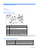
Hardware features In this section Board components ................................................................................................................................... 5 Controller specifications ............................................................................................................................
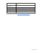
Temperature range Operating, 10° to 35°C (50° to 95°F); storage, -20° to 55°C (-4° to 131°F) Relative humidity (noncondensing) Operating, 10% to 70%; storage, 5% to 90% RAID levels supported 0, 1, 1+0, 5, ADG (also called RAID 6) Connector type Compatible with full-length 3.3-V, 64-bit PCI-X or PCI slot Transfer rate Up to 1.0 GB/s at 133 MHz (64-bit) Number of SAS ports SAS transfer rate 2 (1 internal, and 1 that can be used as internal or external) Up to 1.
Overview of the installation procedure In this section Installing the controller in an unconfigured server ......................................................................................... 7 Installing the controller in a previously-configured server ............................................................................... 7 Installing the controller in an unconfigured server New HP ProLiant server models autoconfigure when they are powered up for the first time.
7. Disconnect peripheral devices. 8. Install the controller hardware ("Installing the controller hardware" on page 9). 9. Connect storage devices to the controller ("Connecting external storage" on page 11, "Connecting storage devices" on page 10). 10. Reconnect peripheral devices and the AC power supply to the server. 11. Power up peripheral devices. 12. Power up the server. 13. Update the controller firmware ("Methods for updating the firmware" on page 12). 14.
Installing the controller hardware In this section Before beginning the installation ................................................................................................................ 9 Preparing the server ................................................................................................................................. 9 Installing the controller board ....................................................................................................................
2. Select an available 3.3-V, 64-bit full-length PCI or PCI-X slot. 3. If the controller is being hot-plugged, power down the slot. 4. Remove the slot cover or open the hot-plug latch. Save the retaining screw if one is present. 5. Slide the controller board along the slot alignment guide, and press the board firmly into the slot so that the contacts on the board edge are properly seated in the system board connector. 6.
CAUTION: Do not operate the server for long periods with the access panel open or removed. Operating the server in this manner results in improper airflow and improper cooling that can lead to thermal damage. 5. If the added drives are not hot-pluggable, power up the system. Connecting external storage 1. Power down the server. 2. Connect an external SAS cable to the external port of the controller.
Updating the firmware In this section Methods for updating the firmware........................................................................................................... 12 Methods for updating the firmware To update the firmware on the server, controller, or hard drives, use Smart Components. These components are available on the Firmware Maintenance CD. A more recent version of a particular server or controller component might be available on the support page of the HP website (http://www.hp.
Configuring an array In this section Utilities available for configuring an array................................................................................................. 13 Utilities available for configuring an array Three utilities are available for configuring an array on an HP Smart Array controller: ORCA, CPQONLIN, and ACU. • ORCA is a simple utility that is used mainly to configure the first logical drive in a new server before the operating system is loaded.
Setting the boot controller and controller order In this section Setting a controller as the boot controller .................................................................................................. 14 Setting the controller order ...................................................................................................................... 14 Setting a controller as the boot controller The following procedure enables you only to set a controller as the boot controller.
5. Exit from the utility. For more information about using RBSU, refer to the HP ROM-Based Setup Utility User Guide or the server setup and installation guide. These documents are both available on the Documentation CD supplied in the server kit.
Installing device drivers and Management Agents In this section Installing device drivers........................................................................................................................... 16 Installing Management Agents .................................................................................................................
Upgrading or replacing controller options In this section Replacing a battery ................................................................................................................................ 17 Replacing a battery WARNING: There is a risk of explosion, fire, or personal injury if the battery pack is not properly handled. Refer to "Battery replacement notice (on page 34)" before installing or removing any item that contains a battery pack.
b. Lift the battery pack off the cache board (2). 4. Remove the secondary cache battery pack: a. Unhook the wire retainer that holds the battery pack to the controller board (1). b. While holding the battery in one hand, pull the plastic retainer tabs up and push them through to the other side of the controller board (2). 5. Replace whichever battery is degraded. 6. Reinstall the batteries on the cache board and the controller board. 7. Reinstall the cache board and its battery on the controller.
Replacing, moving, or adding hard drives In this section Identifying the status of a hard drive ......................................................................................................... 19 Recognizing hard drive failure................................................................................................................. 20 Replacing hard drives .............................................................................................................................
Online/activity LED (green) Fault/UID LED (amber/blue) Interpretation Flashing regularly (1 Hz) Amber, flashing regularly (1 Hz) Do not remove the drive. Removing a drive may terminate the current operation and cause data loss. The drive is part of an array that is undergoing capacity expansion or stripe migration, but a predictive failure alert has been received for this drive. To minimize the risk of data loss, do not replace the drive until the expansion or migration is complete.
Effects of a hard drive failure When a hard drive fails, all logical drives that are in the same array are affected. Each logical drive in an array might be using a different fault-tolerance method, so each logical drive can be affected differently. • RAID 0 configurations cannot tolerate drive failure. If any physical drive in the array fails, all nonfault-tolerant (RAID 0) logical drives in the same array will also fail.
Replacing hard drives The most common reason for replacing a hard drive is that it has failed. However, another reason is to gradually increase the storage capacity of the entire system. If you insert a hot-pluggable drive into a drive bay while the system power is on, all disk activity in the array pauses for a second or two while the new drive is spinning up.
Automatic data recovery (rebuild) When you replace a hard drive in an array, the controller uses the fault-tolerance information on the remaining drives in the array to reconstruct the missing data (the data that was originally on the replaced drive) and write it to the replacement drive. This process is called automatic data recovery, or rebuild. If fault tolerance is compromised, this data cannot be reconstructed and is likely to be permanently lost.
Observation Cause of rebuild termination None of the drives in the array have an illuminated amber Fault LED. One of the drives in the array has experienced an uncorrectable read error. The replacement drive has an illuminated amber Fault LED. The replacement drive has failed. One of the other drives in the array has an illuminated amber Fault LED. The drive with the illuminated Fault LED has now failed. Each of these situations requires a different remedial action.
Upgrading hard drive capacity You can increase the storage capacity on a system even if there are no available drive bays by swapping drives one at a time for higher capacity drives. This method is viable as long as a fault-tolerance method is running. CAUTION: Because it can take up to 15 minutes per gigabyte to rebuild the data in the new configuration, the system is unprotected against drive failure for many hours while a given drive is upgraded.
4. Power up the system. If a 1724 POST message appears, drive positions were changed successfully and the configuration was updated. If a 1785 (Not Configured) POST message appears: a. Power down the system immediately to prevent data loss. b. Return the drives to their original locations. c. 5. Restore the data from backup, if necessary. Verify the new drive configuration by running ORCA or ACU ("Configuring an array" on page 13).
Diagnosing array problems In this section Controller board runtime LEDs.................................................................................................................. 27 Cache module LEDs................................................................................................................................ 28 Diagnostic tools .....................................................................................................................................
LED ID Color LED name and interpretation 10 Amber CR509: Controller Failure LED. The controller hardware has detected an error. Controller CPU activity level Item 6 status Item 7 status 0–25% Off Blinking 25–50% Blinking Off 50–75% On steadily Off 75–100% On steadily On steadily Cache module LEDs Item 1 (amber LED) Item 2 (green LED) Interpretation -- Steady glow The cache batteries are being charged.
Item 1 (amber LED) Item 2 (green LED) Slow blink (once every 16 seconds) Interpretation This display pattern might occur after the system is powered down. It indicates that the cache contains data that has not yet been written to the drives. Restore system power as soon as possible to prevent data loss. (The battery lifetime depends on the cache module size. For further information, refer to the controller QuickSpecs on the HP website (http://www.hp.com).
Electrostatic discharge In this section Preventing electrostatic discharge............................................................................................................. 30 Grounding methods to prevent electrostatic discharge ................................................................................ 30 Preventing electrostatic discharge To prevent damaging the system, be aware of the precautions you need to follow when setting up the system or handling parts.
Regulatory compliance notices In this section Federal Communications Commission notice ............................................................................................. 31 Canadian notice (Avis Canadien) ............................................................................................................ 32 European Union regulatory notice ............................................................................................................ 33 BSMI notice ..........................
to radio communications. However, there is no guarantee that interference will not occur in a particular installation. If this equipment does cause harmful interference to radio or television reception, which can be determined by turning the equipment off and on, the user is encouraged to try to correct the interference by one or more of the following measures: • Reorient or relocate the receiving antenna. • Increase the separation between the equipment and receiver.
This Class A digital apparatus meets all requirements of the Canadian Interference-Causing Equipment Regulations. Cet appareil numérique de la classe A respecte toutes les exigences du Règlement sur le matériel brouilleur du Canada. Class B equipment This Class B digital apparatus meets all requirements of the Canadian Interference-Causing Equipment Regulations. Cet appareil numérique de la classe B respecte toutes les exigences du Règlement sur le matériel brouilleur du Canada.
Japanese notice Korean notice Class A equipment Class B equipment Battery replacement notice This component uses a nickel metal hydride (NiMH) battery pack.
WARNING: There is a risk of explosion, fire, or personal injury if a battery pack is mishandled. To reduce this risk: • Do not attempt to recharge the batteries if they are disconnected from the controller. • Do not expose the battery pack to water, or to temperatures higher than 60°C (140°F). • Do not abuse, disassemble, crush, or puncture the battery pack. • Do not short the external contacts. • Replace the battery pack only with the designated HP spare.
Acronyms and abbreviations ACU Array Configuration Utility ADG Advanced Data Guarding (also known as RAID 6) ADU Array Diagnostics Utility BBWC battery-backed write cache CPQONLIN NetWare Online Array Configuration Utility ORCA Option ROM Configuration for Arrays POST Power-On Self Test RBSU ROM-Based Setup Utility SA Smart Array SIM Systems Insight Manager Acronyms and abbreviations 36
Index A drives, adding 26 drives, moving 25 ACU (Array Configuration Utility) 13 adding drives 26 ADU (Array Diagnostic Utility) 29 array controller installation overview 7 array expansion 26 array, configuring 13 array, moving 25 automatic data recovery (rebuild) 23 E B F batteries, replacing 17 battery replacement notice 34 board components 5 BSMI notice 33 failure, hard drive 20 fault tolerance, compromised 21 Federal Communications Commission (FCC) notice 31, 32 firmware, updating 12 C cable par
L U LEDs, cache module 28 LEDs, controller 27 LEDs, hard drive 19 logical drive capacity extension 26 logical drive, creating 13 updating the firmware 12 upgrading drive capacity 25 M Management Agents, updating 16 moving an array 25 O ORCA (Option ROM Configuration for Arrays) 13, 14 overview of installation process 7 P parallel SCSI drives, compatibility of 10, 11 POST error messages 20, 29 power requirements 5 R rebuild, abnormal termination of 23 rebuild, description of 23 rebuild, time required