HP Smart Array P700m Controller for HP ProLiant Servers User Guide Part Number 456549-001 October 2007 (First Edition)
© Copyright 2007 Hewlett-Packard Development Company, L.P. The information contained herein is subject to change without notice. The only warranties for HP products and services are set forth in the express warranty statements accompanying such products and services. Nothing herein should be construed as constituting an additional warranty. HP shall not be liable for technical or editorial errors or omissions contained herein. Microsoft and Windows are U.S. registered trademarks of Microsoft Corporation.
Contents Hardware features ........................................................................................................................ 5 Main components on the controller board .................................................................................................... 5 Controller specifications ............................................................................................................................. 5 Overview of the installation procedure ........................
Regulatory compliance notices ..................................................................................................... 32 European Union regulatory notice ............................................................................................................. 32 BSMI notice ............................................................................................................................................ 32 Korean class A notice .....................................................
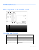
Hardware features Main components on the controller board Item ID Description 1 Status LEDs 2 Connector (not used on HP ProLiant servers) 3 Cache module (also known as BBWC or array accelerator) 4 Connector for cache battery 5 Mezzanine connector to system board Controller specifications Feature Details Board type Type I 4-port PCIe mezzanine board Dimensions 11.3 cm × 10.0 cm × 2.0 cm (4.5 in × 4.0 in × 0.8 in) Type of drives supported 3 Gb/s SAS or 1.
RAID levels supported 0, 1, 1+0, and 5; if the battery is used, RAID 6 is also supported Type of connector Grid array mezzanine connector Transfer rate Up to 2 GB/s in each direction Maximum number of physical drives 108 Maximum number of logical drives 32 Maximum size of a logical drive More than 2 TB Cache size 72 bits, 512 MB (64 MB is used by the onboard processor) Spare battery part number 453779-001 Time required to recharge battery From 15 minutes to 2 hours, depending on the initial
Overview of the installation procedure Installing the controller in an unconfigured server blade New HP ProLiant server models autoconfigure when they are powered up for the first time. For more information about the autoconfiguration process, see the server-specific setup and installation guide or the HP ROM-Based Setup Utility User Guide. These guides are available on the server Documentation CD.
4. Power down the server blade. 5. Remove the server blade from the enclosure. 6. Remove the access panel from the server blade. 7. Install the controller hardware ("Installing the controller hardware" on page 9). 8. Reinstall the access panel. 9. Reinstall the server blade in the enclosure. 10. Install an HP 3Gb SAS BL-c Pass-Thru Module in the enclosure. 11. Connect the server blade to the pass-thru module. 12. Connect the pass-thru module to a drive enclosure. 13.
Installing the controller hardware Preparing the server blade 1. Back up all data. 2. Close all applications. 3. Power down the server blade. CAUTION: In systems that use external data storage, be sure that the server is the first unit to be powered down and the last to be powered back up. Taking this precaution ensures that the system does not erroneously mark the drives as failed when the server is powered up. 4. Remove the server blade from the enclosure.
Updating the firmware Methods for updating the firmware To update the firmware on the server, controller, or hard drives, use Smart Components. These components are available on the Firmware Maintenance CD. A more recent version of a particular server or controller component might be available on the support page of the HP website (http://www.hp.com/support). Components for controller and hard drive firmware updates are also available from the software and drivers page for storage products (http://www.hp.
Configuring an array Utilities available for configuring an array Two utilities are available for configuring an array on this controller: • ORCA is a simple utility that is used mainly to configure the first logical drive in a new server before the operating system is loaded. • ACU is an advanced utility that enables you to perform many complex configuration tasks.
Setting the boot controller and controller order Setting a controller as the boot controller The following procedure enables you only to set a controller as the boot controller. If you also want to adjust the boot order settings of other controllers in the system, use RBSU instead ("Setting the controller order" on page 12). 1. Confirm that the controller is connected to a logical drive. (If it is not, it cannot be set as the boot controller.) 2. Perform a normal system shutdown. 3. Restart the server.
For more information about using RBSU, refer to the HP ROM-Based Setup Utility User Guide or the server setup and installation guide. These documents are both available on the Documentation CD supplied in the server kit.
Installing device drivers and Management Agents Installing device drivers The drivers for the controller are located on the Support Software CD or the SmartStart CD that is provided in the controller kit. Updates are posted to the HP website (http://www.hp.com/support). Using the Support Software CD: Instructions for installing the drivers from the Support Software CD are given in the leaflet that is supplied with the CD.
Upgrading or replacing controller options Replacing the battery CAUTION: Electrostatic discharge can damage electronic components. Be sure you are properly grounded before beginning this procedure. The method for replacing a battery depends on whether the battery case is mounted on the inner wall of the server chassis by a hook-and-loop strip or located in a hard drive slot. If the battery case is mounted on the inner wall of the server chassis: 1. Back up all data. 2. Close all applications. 3.
8. Pull the right hand portion of the battery case away from the battery pack and simultaneously rotate the battery out of the opening. 9. Position the replacement battery pack in the opening in the battery case as shown. The upper left edge of the battery is under the flanges on the pillars at the left edge of the opening, and the right side of the battery rests on the right pillars.
10. Pull the right hand portion of the battery case away from the battery, and simultaneously rotate the battery pack into the opening. 11. Connect the battery cable to the battery and the cache. Route the battery cable so that the cache and battery can be removed together. (If you need to remove the cache to transfer data, the battery must remain connected to it so that the data is preserved.) 12. Insert the battery case into the hard drive slot. 13. Close the server access panel. 14.
Replacing, moving, or adding hard drives Identifying the status of a hard drive When a drive is configured as a part of an array and connected to a powered-up controller, the condition of the drive can be determined from the illumination pattern of the hard drive status lights (LEDs).
Online/activity LED (green) Fault/UID LED (amber/blue) Interpretation Flashing regularly (1 Hz) Amber, flashing regularly (1 Hz) Do not remove the drive. Removing a drive may terminate the current operation and cause data loss. The drive is part of an array that is undergoing capacity expansion or stripe migration, but a predictive failure alert has been received for this drive. To minimize the risk of data loss, do not replace the drive until the expansion or migration is complete.
CAUTION: Sometimes, a drive that has previously been failed by the controller may seem to be operational after the system is power-cycled or (for a hot-pluggable drive) after the drive has been removed and reinserted. However, continued use of such marginal drives may eventually result in data loss. Replace the marginal drive as soon as possible. Effects of a hard drive failure When a hard drive fails, all logical drives that are in the same array are affected.
b. Recreate the partitions. c. Restore all data from backup. To minimize the risk of data loss that is caused by compromised fault tolerance, make frequent backups of all logical volumes. Replacing hard drives The most common reason for replacing a hard drive is that it has failed. However, another reason is to gradually increase the storage capacity of the entire system.
• Do not remove a second drive from an array until the first failed or missing drive has been replaced and the rebuild process is complete. (The rebuild is complete when the Online/Activity LED on the front of the drive stops blinking.) The following cases are exceptions: o In RAID 6 (ADG) configurations, any two drives in the array can be replaced simultaneously.
CAUTION: If the Online/Activity LED on the replacement drive does not light up while the corresponding LEDs on other drives in the array are active, the rebuild process has abnormally terminated. The amber Fault LED of one or more drives might also be illuminated. Refer to "Abnormal termination of a rebuild (on page 23)" to determine what action you must take.
2. Remove the drive that was originally to be replaced, and reinsert the replacement physical drive. The rebuild process automatically restarts. 3. When the rebuild process has finished, replace the newly failed drive. However, if the newly failed drive has not recovered: 1. Remove the drive that was originally to be replaced, and reinsert the replacement physical drive. 2. Replace the newly failed drive. 3. Restore data from backup.
• The controller is not running capacity expansion, capacity extension, or RAID or stripe size migration. • The controller is using the latest firmware version (recommended). If you want to move an array to another controller, all drives in the array must be moved at the same time. When all the conditions have been met: 1. Back up all data before removing any drives or changing configuration.
The expansion process is illustrated in the following figure, in which the original array (containing data) is shown with a dashed border, and the newly added drives (containing no data) are shown unshaded. The array controller adds the new drives to the array and redistributes the original logical drives over the enlarged array one logical drive at a time. This process liberates some storage capacity on each physical drive in the array.
Diagnosing array problems Controller board runtime LEDs Immediately after you power up the server, the controller runtime LEDs illuminate briefly in a predetermined pattern as part of the POST sequence. At all other times during server operation, the illumination pattern of the runtime LEDs indicates the status of the controller, as described in the following table. LED ID Color LED name and interpretation 1 Amber CR10: Thermal Alert LED. Not used on this controller. 2 Amber CR9: System Error LED.
LED ID Color LED name and interpretation 10 Green CR8: Idle Task LED. This LED, together with the Gas Pedal LED, indicates the amount of controller CPU activity. For details, see the following table. Gas Pedal LED status Idle Task LED status Controller CPU activity level Off Blinking 0–25% Blinking Off 25–50% On steadily Off 50–75% On steadily On steadily 75–100% Battery pack LEDs Item ID Color Description 1 Green System Power LED.
LED3 pattern LED4 pattern Interpretation — One blink every two seconds The system is powered down, and the cache contains data that has not yet been written to the drives. Restore system power as soon as possible to prevent data loss. Data preservation time is extended any time that 3.3 V auxiliary power is available, as indicated by LED 2. In the absence of auxiliary power, battery power alone preserves the data. A fullycharged battery can normally preserve data for at least two days.
Smart Array controllers produce diagnostic error messages (POST messages) at reboot. Many POST messages are self-explanatory and suggest corrective actions. For more information about POST messages, see the HP Servers Troubleshooting Guide. • HP Insight Diagnostics HP Insight Diagnostics is a tool that displays information about the system hardware configuration and performs tests on the system and its components (including hard drives if they are connected to Smart Array controllers).
Electrostatic discharge Preventing electrostatic discharge To prevent damaging the system, be aware of the precautions you need to follow when setting up the system or handling parts. A discharge of static electricity from a finger or other conductor may damage system boards or other static-sensitive devices. This type of damage may reduce the life expectancy of the device. To prevent electrostatic damage: • Avoid hand contact by transporting and storing products in static-safe containers.
Regulatory compliance notices European Union regulatory notice This product complies with the following EU Directives: • Low Voltage Directive 2006/95/EC • EMC Directive 2004/108/EC Compliance with these directives implies conformity to applicable harmonized European standards (European Norms) which are listed on the EU Declaration of Conformity issued by Hewlett-Packard for this product or product family.
Korean class A notice Battery replacement notice This component uses a nickel metal hydride (NiMH) battery pack. WARNING: There is a risk of explosion, fire, or personal injury if a battery pack is mishandled. To reduce this risk: • Do not attempt to recharge the batteries if they are disconnected from the controller. • Do not expose the battery pack to water, or to temperatures higher than 60°C (140°F). • Do not abuse, disassemble, crush, or puncture the battery pack. • Do not short the external contacts.
Acronyms and abbreviations ACU Array Configuration Utility ADG Advanced Data Guarding (also known as RAID 6) ADU Array Diagnostics Utility ASIC Application Specific Integrated Circuit BBWC battery-backed write cache IML Integrated Management Log ORCA Option ROM Configuration for Arrays POST Power-On Self Test RBSU ROM-Based Setup Utility Acronyms and abbreviations 34
Index A ACU (Array Configuration Utility) 11 adding drives 25 ADU (Array Diagnostic Utility) 29 Array Configuration Utility (ACU) 11 array controller installation overview 7 Array Diagnostic Utility (ADU) 29 array expansion 25 array, configuring 11 array, moving 24 automatic data recovery (rebuild) 22 B batteries, replacing 15 batteries, specifications 5 battery pack LEDs 28 battery replacement notice 33 board components 5 boot controller, setting 12 BSMI notice 32 C cache, features 5 compromised fault to
L T LEDs, battery pack 28 LEDs, controller 27 LEDs, hard drive 18 logical drive capacity extension 25 logical drive, creating 11 logical drives, maximum number of 5 Taiwan battery recycling notice 33 temperature requirements 5 troubleshooting 27, 29 M U unconfigured server, installation in 7 updating the firmware 10 upgrading drive capacity 24 Management Agents, updating 14 moving an array 24 moving drives 24 O Option ROM Configuration for Arrays (ORCA) 11, 12 ORCA (Option ROM Configuration for Array