AM311A Smart Array P411/256 Controller for HP Integrity Servers Installation Guide Abstract This guide includes procedures to install, update, and configure HP Smart Array P411/256 controllers on HP Integrity servers.
© Copyright 2011 Hewlett-Packard Development Company, L.P. Legal notice The information contained herein is subject to change without notice. The only warranties for HP products and services are set forth in the express warranty statements accompanying such products and services. Nothing herein should be construed as constituting an additional warranty. HP shall not be liable for technical or editorial errors or omissions contained herein. Confidential computer software.
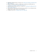
Contents 1 Controller overview.....................................................................................5 2 Windows installation..................................................................................6 Installation overview..................................................................................................................6 3 HP-UX installation.......................................................................................8 Installation overview.....................
B Cable kits................................................................................................
1 Controller overview This chapter provides an overview of the physical characteristics of the HP Smart Array P411/256 Controller. Figure 1 HP AM311A Smart Array 411 controller components 1 1 2 Connector for SAS miniports 1 and 2, each 4x wide. Cache module (also known as array accelerator). 2 3 3 4 Status LEDs (runtime LEDs). To interpret the illumination pattern of these LEDs, see Table 2 (page 31).
2 Windows installation This chapter describes installing Smart Array P411/256 Controllers on HP Integrity servers running Microsoft Windows. Installation overview WARNING! The HP AM311A Smart Array P411 controller does not support SATA disks in its initial release with adapter firmware version 3.30. SATA support will be added in a future firmware update. For the latest information on recommended adapter firmware, see the HP Smart Array RAID Controllers Support Matrix at: http://www.hp.
13. Update the controller firmware, if necessary. See “Verifying and updating controller firmware offline” (page 14). 14. Determine whether the controller is in RAID mode; if not, then set it to RAID mode. See “Determining and setting the controller mode” (page 19). 15. Update the storage enclosure firmware, if necessary. See “Verifying and updating enclosure firmware offline” (page 21). 16. (Optional) Set the Smart Array P411/256 as the boot controller.
3 HP-UX installation This chapter describes installing Smart Array P411/256 Controllers on HP Integrity servers running HP-UX. Installation overview WARNING! The HP AM311A Smart Array P411 controller does not support SATA disks in its initial release with adapter firmware version 3.30. SATA support will be added in a future firmware update. For the latest information on recommended adapter firmware, see the HP Smart Array RAID Controllers Support Matrix at: http://www.hp.com/go/smart-array-raid-docs.
12. 13. 14. 15. Reconnect the peripheral devices and the AC power supply to the server.. Power on the peripheral devices and storage devices. Power on the server. Update the controller firmware, if necessary. See “Verifying and updating controller firmware offline” (page 14). 16. Determine whether the controller is in HBA mode or RAID mode; if necessary, change the mode to suit your configuration.
1. Go to the HP Software Depot website at: http://software.hp.com. 2. 3. 4. 5. 6. 7. Search for RAID-01. Click Receive for Free. If prompted, sign in with your HP Passport account credentials or create a new account. In the Software Specifications section, select HP-UX 11.31.1005 Itanium (or later). Complete all other required fields, then click Next. Follow the prompts to download the driver bundle and installation instructions.
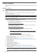
4 Installing, verifying, and configuring the controller Card installation varies by server type and model. The following procedures are a general guideline for installing the card. For more information, see your server documentation. WARNING! To reduce the risk of personal injury or damage to the equipment, consult the server documentation safety information.
2. Connect an external SAS cable to the external port of the controller: a. Pull back the tab on the mini SAS 4x connector on the cable. b. Insert the cable connector into the external port of the controller. c. Release the tab. For more information on SAS cables, see Appendix B (page 36). 3. 4. 5. Connect the other end of the cable to the SAS input connector of the external storage enclosure or tape devices.
1. Prepare to run saupdate from the Offline Diagnostics CD or the UEFI partition: • To run saupdate from the Offline Diagnostic CD: a. Place the Offline Diagnostic CD containing saupdate.efi in the CD drive before booting the system. b. Boot the system to the UEFI Shell prompt. c. Locate the cdrom entry in the list of mapped devices, and change to the device by entering its associated fs number (for example, fs0) under UEFI Shell prompt. d.
2. Use the reconnect -r shell command to reinitialize the cards connected to the server. As the command executes, watch for a message indicating that one or more tape devices has been detected. For example: Shell> reconnect -r HP PCI-X 2Port 2Gb Fibre Channel Adapter (driver 1.50, firmware 3.03.171) HP PCI-X 2Port 2Gb Fibre Channel Adapter (driver 1.50, firmware 3.03.171) HP Smart Array P411 Controller (version 3.66) Currently the controller is in HBA mode HP Smart Array P411 Controller (version 3.
Smart Array Offline Firmware Update Utility Version 2.09.10.02 (C) Copyright 2009 Hewlett-Packard Development Company, L.P. ******************************************************************************** Seg 1 Bus 55 Dev Func 0 0 Description HP Smart Array P812 External Enclosures Connected : Index Description 2 MDS600 3 MDS600 4 P812 INT EXP 1 71 0 0 C7 0 0 1 E4 0 0 0 3.22 0 3.22 0 Version 0052 0052 3.
Updating the controller firmware NOTE: The following is a generic procedure to update firmware from the UEFI shell. HP recommends that you follow the procedures supplied with the update package to install the firmware update. Use saupdate from the UEFI Shell to update the firmware image on the controller.: To update the controller firmware with saupdate, follow these steps: 1. Prepare to run saupdate from the Offline Diagnostics CD or the UEFI partition: • To run saupdate from the Offline Diagnostic CD: a.
2. Use saupdate UPDATE to update the firmware on the controller. To update a single controller, the syntax of the saupdate UPDATE command is as follows: saupdate UPDATE For example, to update the controller at segment 1, bus E4, device 0, function 0 from the example output above: fs0:\> saupdate UPDATE 1:E4:0:0 sandman.
2. Use saupdate list to confirm that the correct firmware version is installed. See “Verifying the controller firmware” (page 14). For example: fs0:\EFI\TOOLS> saupdate list ******************************************************************************** Smart Array Offline Firmware Update Utility Version 2.09.10.02 (C) Copyright 2009 Hewlett-Packard Development Company, L.P.
For querying/changing Controller mode: saupdate GET_MODE [ | all | ] saupdate SET_MODE [ | all | ] [ hba | raid ] [-f] Error messages The following error messages might appear when using saupdate: • When keyword LIST or UPDATE is misspelled or extra parameters are specified: Error: Syntax Error Usage: saupdate LIST or saupdate UPDATE [ | all ] • When the controller ID in the saupdate UPDATE command is not correct: No matching controller found • Whe
Table 1 strings Meaning A controller having the PCI segment id, bus id, device id and function id is addressed all Addresses all controllers in the system Controllers of a particular type indicated by the string are addressed SET_MODE IMPORTANT: If you are using HBA mode, do not install any disk that has previously been a part of a RAID volume into the system. Use set_mode to change the mode of the controller.
NOTE: Commands are not case-sensitive. A system reset is not required after a mode change. NOTE: After changing the mode, perform a reconnect -r command at UEFI. Verifying and updating enclosure firmware offline Follow the procedures in this section to verify and update the firmware in an external enclosure. Verifying the enclosure firmware Use saupdate from the UEFI Shell to verify the firmware image on the enclosure. To verify the enclosure firmware with saupdate, follow these steps: 1.
2. • Use saupdate LIST to display all detected Smart Array controllers along with the active firmware versions. For example: fs0:\EFI\TOOLS> saupdate list ******************************************************************************** Smart Array Offline Firmware Update Utility Version 2.09.10.02 (C) Copyright 2009 Hewlett-Packard Development Company, L.P.
Updating the enclosure firmware NOTE: The following is a generic procedure to update firmware from the UEFI shell. HP recommends that you follow the procedures supplied with the update package to install the firmware update. Use saupdate from the UEFI Shell to update the firmware image on the enclosure. To update the enclosure firmware with saupdate, follow these steps: 1. Prepare to run saupdate from the Offline Diagnostics CD or the UEFI partition: • To run saupdate from the Offline Diagnostic CD: a.
Verifying the firmware update 1. 2. After updating the firmware, cycle the power on the system and on any external JBODS connected to the system. Use saupdate LIST to confirm that the correct firmware version is installed. See “Verifying the controller firmware” (page 14). For example: fs0:\EFI\TOOLS> saupdate list ******************************************************************************** Smart Array Offline Firmware Update Utility Version 2.09.10.
saupdate UPDATE [ | all | ] For Enclosure Flash: saupdate UPDATE [ ] saupdate UPDATE [ all_encl ] For querying/changing Controller mode: saupdate GET_MODE [ | all | ] saupdate SET_MODE [ | all | ] [ hba | raid ] [-f] Updating tape device firmware To update tape device firmware, use the HP StorageWorks Library and Tape Tools software.
4E 4F 50 5C 5D 5E 5F 60 62 64 66 67 68 69 6A 6B 6C 6D 6E 70 71 72 73 00000020 00000020 00000020 00000010 00000011 00000010 00000011 00000010 00000021 00000020 00000020 00000010 00000010 00000010 00000010 00000010 00000010 00000010 00000010 00090404 00000031 00000020 00000030 1 B D D D B D ? ? D D D ? ? ? ? ? ? ? ? ? D ? ? X X - - 2 6 USB Bus Driver - 2 - Usb Bot Mass Storage Driver - 2 - Generic USB Mass Storage Driver - 22 - Generic Disk I/O Driver - 7 14 Partition Driver(MBR/GPT/El Torito) - 2 - FAT
4. To launch ORCA, enter the drvcfg -s command. For example: fs1:\P411> drvcfg -s 27 29 Set Configuration Options NOTE: In order for ORCA to launch, at least one disk must be connected to the Smart Array controller. NOTE: In order for ORCA to launch, there must be 32 or fewer logical drives. If more than 32 logical drives are defined, a warning appears indicating that the number of logical drives that can be handled by ORCA has been exceeded.
Creating a logical drive 1. At the ORCA main menu, select Create Logical Drive. 2. Select the physical disks to be included in the logical drive in the Available Physical Drives section. To select the Raid Configurations section and select the RAID type for the logical drive, press Tab. To select the Spare section and assign spare disks, as needed, press Tab. To create the logical drive, press Enter. A summary of your choices appears. 3. 4. 5. 6. 7. To save the configuration, press F8.
1. At the ORCA main menu, select Delete Logical Drive. 2. Select a logical drive to be deleted. 3. F3 to delete the logical drive.
4. 30 To acknowledge that the configuration was saved and return to the ORCA Main Menu, press Enter.
5 Troubleshooting This chapter provides an overview of troubleshooting resources. Smart Array P411 controller board runtime LEDs The Smart Array P411 Controller board has nine runtime LEDs that indicate activities and error conditions. Figure 3 Smart Array P411 controller board runtime LEDs 1 2 3 4 5 6 7 8 9 Table 2 Interpreting Smart Array 411 runtime LEDs LED ID Color Name LED name and interpretation 1 Amber DS9 System Error LED.
Table 3 Determining Smart Array P411 controller CPU activity level DS7 (Gas Pedal) Status DS8 (Idle Task) Status Controller CPU activity level Off Flashing 0 to 25% Flashing Off 25 to 50% On steadily Off 50% to 75% On steadily On steadily 75% to 100% NOTE: During server power on, each runtime LED illuminates randomly until POST completes. POST messages Smart Array Controllers provide diagnostic error messages to the server BIOS at reboot.
6 Support and other resources About this document This document describes how to install Smart Array P411/256 Controllers in HP Integrity servers. Intended audience This document is for system and network administrators responsible for installing, configuring, and managing fault tolerant data storage. Administrators must know operating system concepts, commands, and configuration. Administrators also must know proper electrostatic discharge (ESD) safety procedures for installing the controller hardware.
Include the document title, manufacturing part number, and any comment, error found, or suggestion for improvement you have concerning this document.
A Electrostatic discharge This appendix discusses ways to prevent damage to your system due to Electrostatic Discharge (ESD). Handling parts To prevent damage to your system, you must take precautions when setting up the system or handling parts. A discharge of static electricity from a finger or other conductor can damage system boards or other static-sensitive devices. This type of damage can reduce the life expectancy of the device.
B Cable kits This appendix provides details on the internal and external cable kits that are available for HP Smart Array SAS controllers. Table 4 Internal SAS cable kits Description Part Number Multi-lane A cable 389647-B21 Host fan cable 389650-B21 Target fan cable 389653-B21 Multi-lane B cable 389659-B21 Multi-lane 76-cm (30-in) cable 389662-B21 Multi-lane 48-cm (19-in) cable 391330-B21 Table 5 lists external cables that can be used with HP Smart Array SAS controllers.