
User's Manual

Diagnosing array problems 35
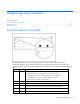
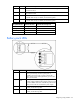
LED ID Color LED name and interpretation
7 Green
CR506: Command Outstanding LED. The controller is working on a command
from the host driver.
8 Green
CR505: Controller Heartbeat LED. This LED flashes every 2 seconds to indicate
the controller health.
9 Green
CR504: Gas Pedal LED. This LED, together with item 10, indicates the amount of
controller CPU activity. For details, see the following table.
10 Green
CR503: Idle Task LED. This LED, together with item 9, indicates the amount of
controller CPU activity. For details, see the following table.
Gas pedal LED status Idle task LED status Controller CPU activity level
Off Blinking 0–25%
Blinking Off 25–50%
On steadily Off 50–75%
On steadily On steadily 75–100%
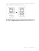
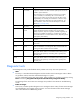
Battery pack LEDs
Item ID Color Description
1 Green
System Power LED. This LED glows steadily when the
system is powered up and 12 V system power is
available. This power supply is used to maintain the
battery charge and provide supplementary power to the
cache microcontroller.
2 Green
Auxiliary Power LED. This LED glows steadily when 3.3V
auxiliary voltage is detected. The auxiliary voltage is used
to preserve BBWC data and is available any time that the
system power cords are connected to a power supply.
3 Amber
Battery Health LED. To interpret the illumination patterns of
this LED, see the following table.
4 Green
BBWC Status LED. To interpret the illumination patterns of
this LED, see the following table.