
HP FireWire®/IEEE 1394a PCIe x1 Card Installation Guide

HP FireWire®/IEEE 1394a
PCIe x1 Card
Installation Guide
© Copyright 2010, 2012 Hewlett-Packard Development Company, L.P. The
information contained herein is subject to change without notice.The only
warranties for HP products and services are set forth in the express warranty
statements accompanying such products and services. Nothing herein should
be construed as constituting an additional warranty. HP shall not be liable for
technical or editorial errors or omissions contained herein.
Printed in
Second Edition: October 2012
*631518-B22*
Kit Contents
• HP FireWire®/IEEE 1394a PCIe x1 card (with full-height
expansion bracket attached)
• SATA to SATA split power extension cable
• Low profile expansion bracket to replace the full-height expansion
bracket required on some computer models
Features
The HP FireWire®/IEEE 1394a PCIe x1 card includes the following
features:
• 1394a interface with data transfer rates of 400, 200, and 100
Mbps.
• 1394a compliant physical layer with 2 external 1394a 6-pin ports
and 1 internal port with pin headers for connecting a third
external 1394a port.
• Fits conveniently in a half-height or full height expansion slot in the
computer with convenient half-height bracket as well as the default
full-height bracket.
• Power to external devices is individually current limited to 1.5A per
port.
To determine the compatibility of this product with your HP computer,
see QuickSpecs online at http://www.hp.com/go/productbulletin
.
Installing the 1394a PCIe x1 Card
1. Turn off power to the system and disconnect the power cord from
the power outlet.
WARNING! To avoid the risk of serious injury, ensure that the
power cord is unplugged from the electrical outlet at the wall
before installing the PCIe x1 card. Failure to do so may expose
you to the risk of electric shock.
CAUTION: To avoid the risk of damage to the system, ensure that
the power cord is unplugged from the electrical outlet at the wall
before installing the PCIe x1 card.
NOTE: Refer to the documentation included with your computer
for detailed information on installing an expansion card
2. Remove the computer cover or access panel.
3. Remove the appropriate expansion slot cover from the rear of the
computer.
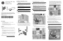
4. A full-height expansion cover bracket is attached to the 1394a
PCIe card. If your computer requires a half-height bracket, remove
two screws that secure the full-height bracket to the card (1),
remove the bracket from the card (2), place the low-profile bracket
on the card (3), and secure the bracket with the two screws (4).
5. Insert the 1394a PCIe x1 card into an available PCIe 2.0
expansion slot in the computer.
NOTE: The 1394a PCIe x1 card has a PCIe 2.0 5 GHz interface.
For optimal performance, install this card in a PCIe 2.0 slot.
Installing it in a PCIe 1.0 slot could cause the card to run at a
reduced 2.5 GHz throughput. Refer to the documentation included
with your computer for detailed instructions on installing an
expansion card.
6. Look for an available SATA Power connector inside the chassis. If
one is available, do the following:
NOTE: The SATA power cable is only required for bus-powered
devices that consume over 1 amp of power.
• Using the SATA power cable provided, plug the far end of the
cable labeled P3 into the 1394a PCIe card. Plug the other
end of the cable labeled P1 into the available SATA power
cable.
If there is no available SATA power connector inside the chassis,
do the following:
• Disconnect the SATA power cable from the rear of any
available SATA drive, such as a hard drive or optical drive.
• Using the SATA power cable provided in the kit, plug the far
end of the cable labeled P3 into the 1394a PCIe card. Plug
the middle connector on the cable labeled P2 into the rear of
the drive that was disconnected in the previous step. Plug the
other end of the cable labeled P1 into the SATA power cable
that was disconnected from the drive.
7. Replace the computer cover or access panel.
8. Plug in and power on the computer.
9. After powering on the computer, make sure the card is being
recognized by the system (a popup message will display in the
system tray on the Windows taskbar).
10. Connect your 1394a device(s) to the 1394a port(s) on the 1394a
PCIe card. Refer to the device manufacturer's documentation for
specific instructions on connecting a device.
Connecting an External 1394a Port
The 1394a PCIe card is equipped with a 1394a connector on the rear
of the card that can be used to connect an external 1394a port.
CAUTION: If your computer supports a 1394a external port
through the system board, do not disconnect the external port
cable from the system board. Doing this causes the system to fail
at boot.
NOTE: For computers that do not support a 1394a external port
through the system board, connect the external port cable into the
1394a connector on the rear of the card.