SSL2000 Series Library Drive Upgrade Reference Guide First Edition (April 2000) Part Number 187194-001 Compaq Computer Corporation Compaq Confidential – Need to Know Required Writer: Bob Young Project: Compaq StorageWorks SSL2000 Series Library Drive Upgrade Reference Guide Comments: Part Number: 187194-001 File Name: a-frnt.
Notice © 2000 Compaq Computer Corporation. Compaq, the Compaq logo, and StorageWorks Registered in U. S. Patent and Trademark Office. All other product names mentioned herein may be trademarks or registered trademarks of their respective companies. Compaq shall not be liable for technical or editorial errors or omissions contained herein. The information in this document is subject to change without notice.
Contents About This Guide Symbols in Text...........................................................................................................v Symbols on Equipment...............................................................................................vi Cabinet Stability ........................................................................................................vii Getting Help ........................................................................................................
About This Guide This guide is designed to be used as step-by-step instructions for installing a second drive into a Compaq StorageWorks SSL2000 Series Library. Symbols in Text These symbols may be found in the text of this guide. They have the following meanings. WARNING: Text set off in this manner indicates that failure to follow directions in the warning could result in bodily harm or loss of life.
vi Compaq StorageWorks SSL2000 Series Library Drive Upgrade Reference Guide Symbols on Equipment These icons may be located on equipment in areas where hazardous conditions may exist. Any surface or area of the equipment marked with these symbols indicates the presence of electrical shock hazards. Enclosed area contains no operator serviceable parts. WARNING: To reduce the risk of injury from electrical shock hazards, do not open this enclosure.
About This Guide Cabinet Stability WARNING: To reduce the risk of personal injury or damage to the equipment, be sure that: ■ The leveling jacks are extended to the floor. ■ The full weight of the cabinet rests on the leveling jacks. ■ The stabilizing feet are attached to the cabinet if it is a single cabinet installation. ■ The cabinets are coupled together in multiple cabinet installations. ■ Only one component is extended at a time.
viii Compaq StorageWorks SSL2000 Series Library Drive Upgrade Reference Guide Compaq Website The Compaq website has information on this product as well as the latest drivers and Flash ROM images. You can access the Compaq website at http://www.compaq.com. Compaq Authorized Reseller For the name of your nearest Compaq authorized reseller: ■ In the United States, call 1-800-345-1518. ■ In Canada, call 1-800-263-5868. ■ Elsewhere, see the Compaq website for locations and telephone numbers.
Adding a Second Drive Introduction This guide explains how to add a second tape drive to the Compaq StorageWorks SSL2000 Series Library (AIT Library). IMPORTANT: All screws that do not use lock washers, captive washers, or lock nuts must have Loctite 222 applied when parts are reassembled in the field. If you ignore this step, you might cause premature failure of the mechanism.
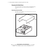
2 Compaq StorageWorks SSL2000 Series Library Drive Upgrade Reference Guide Removing the Outside Cover This section describes how to remove the outside cover from both the tabletop and rackmount versions of the Compaq StorageWorks SSL2000 Series Library. Outside Cover Screw Locations The outside cover for the tabletop version is held in place by four screws at the sides of the unit (see Figure 1). cc00018 Figure 1.
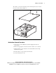
Adding a Second Drive The outside cover for the rackmount version is held in place by two screws at the top-rear of the unit (see Figure 2). cc0019 Figure 2. Outside cover screw locations (rackmount version) Outside Cover Removal Procedures 1. Turn off power to the AIT Library and then unplug it from the AC power source. 2. Remove the appropriate screws that secure the outside cover to the unit. 3. Slide the outside cover toward the rear of the unit until it clears the lip behind the front panel. 4.
4 Compaq StorageWorks SSL2000 Series Library Drive Upgrade Reference Guide Removing the Brace Plate and Upper Drive Mounting Plate The brace plate and upper drive mounting plate must be removed to gain access to the drive area. To remove both plates: 1. Remove the outside cover. 2. Remove the four screws that secure the brace plate to the chassis ( 1 Figure 3). 1 cc0020 Figure 3.
Adding a Second Drive 3. Remove the screws that secure the upper drive mounting plate to the chassis (see Figure 4). 4. Lift out the upper drive mounting plate. cc0021 Figure 4. Upper drive mounting plate removal Compaq Confidential – Need to Know Required Writer: Bob Young Project: Compaq StorageWorks SSL2000 Series Library Drive Upgrade Reference Guide Comments: Part Number: 187194-001 File Name: b-ch1 Adding a Second Drive.
6 Compaq StorageWorks SSL2000 Series Library Drive Upgrade Reference Guide Installing Alignment Pins Four alignment pins need be installed into the new drive prior to installation. Each alignment pin consists of a plastic spacer (top hat) and a screw ( 1 Figure 5). To install the alignment pins: 1. Place a plastic spacer onto each of the four screws. 2. Install the alignment pins at the locations shown ( 1 Figure 5). 1 cc0022 1 Figure 5.
Adding a Second Drive Installing the New Drive To install the new drive: 1. Align the new drive with the holes at the bottom of the chassis. 2. Lower the new drive into the chassis (see Figure 6). cc0023 Figure 6. Installing the new drive Compaq Confidential – Need to Know Required Writer: Bob Young Project: Compaq StorageWorks SSL2000 Series Library Drive Upgrade Reference Guide Comments: Part Number: 187194-001 File Name: b-ch1 Adding a Second Drive.
8 Compaq StorageWorks SSL2000 Series Library Drive Upgrade Reference Guide 3. Connect the power cable 1, serial cable 2, and SCSI cable 3 to the new drive (see Figure 7). 1 2 3 cc0024 Figure 7. Connecting the new drive 4. Secure the upper drive mounting plate to the new drive and chassis using the previously removed retaining screws. 5. Secure the brace place to the chassis using the previously removed retaining screws. 6.