HP StorageWorks XP24000/XP20000 Continuous Access Software User Guide Abstract This guide explains how to use HP StorageWorks XP Continuous Access Software to protect information stored on HP StorageWorks XP24000/XP20000 disk arrays from local disaster by continuously copying local data across Fibre Channel connections to remote XP disk arrays.
© Copyright 2007, 2011 Hewlett-Packard Development Company, L.P. Confidential computer software. Valid license from HP required for possession, use or copying. Consistent with FAR 12.211 and 12.212, Commercial Computer Software, Computer Software Documentation, and Technical Data for Commercial Items are licensed to the U.S. Government under vendor's standard commercial license. The information contained herein is subject to change without notice.
Contents 1 Overview of XP Continuous Access Software..................................................7 XP Continuous Access...............................................................................................................7 Feature Highlights.....................................................................................................................7 Business Benefits.......................................................................................................................
Restriction for Connecting with Former Model of Storage System..............................................48 3 Preparing for XP Continuous Access Operations...........................................50 System Requirements...............................................................................................................50 Requirements and Restrictions for Using XP Continuous Access......................................................51 One-to-One Volume Copy Operations........................
History Operations...............................................................................................................113 Exporting the History File..................................................................................................113 Other Operations.................................................................................................................114 Changing the Option Settings of Storage System..................................................................
HP Websites........................................................................................................................172 Documentation Feedback.......................................................................................................172 A XP Continuous Access Load Balancing and Sidefile Management and Control.173 B Retention of Pair Consistency using the Consistency Group of the XP Continuous Access Synchronous......................................................................
1 Overview of XP Continuous Access Software This chapter provides an overview of XP Continuous Access Software.
Business Benefits XP Continuous Access Software provides the following business benefits: • Supports your business continuity and disaster recovery efforts and plans. • Provides distance replication while maintaining application and data integrity. • Improves business resilience by enabling frequent, nondisruptive disaster recovery testing with an online copy of current and accurate production data. • Improves service levels by reducing planned and unplanned downtime of customer-facing applications.
2 About XP Continuous Access Operations This chapter describes XP Continuous Access operations.
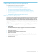
Figure 1 XP Continuous Access Components for Fibre Channel Connection Storage Systems XP Continuous Access operations involve the primary (main) storage systems and the secondary (remote) storage systems (MCUs and RCUs). This document covers XP Continuous Access operations in which the main storage system is an XP24000/XP20000 disk array and the remote storage system is an XP24000/XP20000 disk array (or an XP12000/XP10000 disk array).
Table 2 XP Continuous Access Storage System Mode Mode 549 Description Mode 549 allows you to select if the relevant pair will transit to the suspend status (PFUS) when a P-VOL in the XP Continuous Access synchronous mode receives an update I/O and remote I/O (RIO) from the MCU to the RCU and is not completed within 20 seconds.
operations between the P-VOLs and S-VOLs. The MCU also manages the XP Continuous Access pair status and configuration information. • The RCU is the CU in the remote storage system that controls the S-VOLs of the XP Continuous Access pairs. The RCU assists in managing the XP Continuous Access pair status and configuration (for example, rejects write I/Os to XP Continuous Access S-VOLs). The RCU executes the remote copy operations issued by the MCU.
Synchronous Consistency Groups An XP Continuous Access Synchronous consistency group is a user-defined set of volume pairs. If you specify a consistency group for XP Continuous Access Synchronous pairs, you can issue a command for each group and can ensure the consistency of pairs in the same group. XP Continuous Access Synchronous pairs or TrueCopy for Mainframe synchronous pairs can be registered in an XP Continuous Access Synchronous consistency group.
groups (for example, split and resync group). Consistency groups enable you to maintain update sequence consistency for databases which span multiple volumes, allowing immediate database recovery at the remote site when needed. See “XP Continuous Access Asynchronous Consistency Group Operations” (page 30) for further information on XP Continuous Access Asynchronous consistency group operations.
Initiator Ports and RCU Target Ports The initiator ports are the dedicated Fibre Channel interface ports on the main storage system (MCU) to which the RCUs (RCU target ports) are connected. The initiator ports connect to the RCUs to send write I/O operations directly to the RCUs. Any Fibre Channel interface port of the storage system can be configured as an initiator port.
suspended due to an error condition, the MCU generates sense information that should be transferred to the remote site using the host failover software for effective disaster detection and recovery. XP Continuous Access Remote Copy Operations Figure 2 (page 16) illustrates two types of XP Continuous Access remote copy operations: initial copy and update copy.
Continuous Access pair. This option can only be specified using the XP Continuous Access software (not RAID Manager). • The initial copy priority option allows you to specify the order in which the initial copy operations are performed when creating/resynchronizing multiple XP Continuous Access pairs. This option can only be specified using the XP Continuous Access software (not RAID Manager).
Priority of initial and update copy: In both XP Continuous Access Synchronous and XP Continuous Access Asynchronous, update copy has a higher priority than initial copy. However, initial copy is executed based on the copy pace (3 or 15 tracks); therefore, update copy must wait for this interval if initial copy is being executed. For example, if the copy pace is 15 tracks, the update copy may wait up to 15 tracks (1 cylinder).
differential data to the MCU, and the MCU merges the P-VOL and S-VOL differential data to determine which tracks are out-of sync. This ensures proper resynchronization of the pair. Difference Management The differential data (updated by write I/Os during a split or suspension) between the P-VOL and S-VOL is stored in each bitmap. When a split/suspended pair is resynchronized (pairresync), the MCU merges the P-VOL and S-VOL bitmaps, and the differential data is copied to the S-VOL.
of the cylinders instead of the number which is derived from number of cylinders x 15 to calculate the number of bitmap areas.
The … symbols around a value indicate that the value should be rounded down to the former integer. CAUTION: The bitmap areas that are used for XP Continuous Access are shared with Hitachi TrueCopy™ for Mainframe, XP Continuous Access Journal, Hitachi Universal Replicator™ for Mainframe, and XP External Storage Access Manager Software.
The parameter length and detailed specification of the XP Continuous Access Asynchronous channel command are different than for XP Continuous Access Synchronous RIOs. Ensure that your channel extenders are capable of supporting this command. For further details, contact your HP service representative. Storing Recordsets at the RCU The RCU maintains queues to control the storing of recordsets in the sidefile and commitment of updating records in the S-VOLs.
Figure 3 Selecting and Settling XP Continuous Access Asynchronous Recordsets at the RCU * Since the record set has not yet arrived at the RCU, S2 does not have a time stamp now. Types of Recordsets In addition to host update recordsets, the MCU passes control information to the RCU in special non-update recordsets. These special recordsets indicate when pair status changes and when an MCU power-off sequence is initiated, and also maintain sequence numbers in periods of low-host activities.
within the user-specified offloading timer value, the RCU suspends all XP Continuous Access Asynchronous pairs and resets the channel-command-retry condition to avoid hanging up the MCU. Table 4 (page 24) describes the sidefile threshold values for XP Continuous Access Asynchronous operations and write pending operations and describes the actions that occur when each threshold is reached.
If an XP Continuous Access Synchronous pair and a TrueCopy for Mainframe synchronous pair are registered in the same group, you can ensure the consistency between an XP Continuous Access Synchronous pair and a TrueCopy for Mainframe synchronous pair in the same group. If only XP Continuous Access Synchronous pairs or only TrueCopy for Mainframe synchronous pairs are registered in the group, you can ensure the consistency of the pairs in each group.
Figure 5 Splitting Processing When the Split Command is Issued and there are Volumes in the Consistency Group in I/O Processing If the split command (Pairsplit-r or YKSUSPND) is issued to a consistency group of XP Continuous Access Sychronous pair and if the I/O processing on some volumes in the consistency group has not finished, the split operation to the TrueCopy for Mainframe volume pair is executed for maintaining the data consistency after the track processing of the volume that is in I/O processing
An option must be selected in Business Continuity Manager, although it is not necessary to select an option in RAID Manager. However, no options can make an XP Continuous Access volume prohibit Read access. For details of each option, see the HP StorageWorks RAID Manager User Guide or the HP StorageWorks Business Continuity Manager Software User Guide.
Table 7 (page 28) and Table 8 (page 29) show the status of XP Continuous Access Synchronous pairs and TrueCopy for Mainframe Synchronous pairs and the result of the pair splitting operation performed.
Table 8 Status of XP Continuous Access Synchronous Pairs and TrueCopy for Mainframe Pairs When Pair Splitting is Performed (Business Continuity Manager) Pair Status TrueCopy for Mainframe Synchronous Pairs All pairs are in Duplex status XP Continuous Access All pairs are in PAIR Synchronous pairs status Pairs are in PAIR and PSUS status All pairs are in PSUS status Pairs in Duplex and Suspend status All pairs are in Suspend status XP Continuous Access XP Continuous Synchronous pairs: Access Synchrono
XP Continuous Access Asynchronous Consistency Group Operations XP Continuous Access Asynchronous consistency groups enable update sequence consistency to be maintained across a group of volumes. The P-VOLs and S-VOLs of the pairs in a consistency group must be located within one physical MCU and one physical RCU (1-to-1 requirement).
suspended. If you selected the LU error level, only the affected XP Continuous Access pair will be suspended. NOTE: The Error level pair option is very important for managing XP Continuous Access Asynchronous groups and planning for disaster recovery. The Group error level should be selected for all XP Continuous Access Asynchronous volumes that are essential to disaster recovery. Suspended XP Continuous Access S-VOLs that have the LU error level should not be used for disaster recovery.
Table 9 XP Continuous Access Pair Status Pair Status Description SMPL This volume is not currently assigned to an XP Read/write Continuous Access pair. When this volume is added to an XP Continuous Access pair, its status will change to COPY. Read/write COPY The initial copy operation for this pair is in progress. Read/write This pair is not yet synchronized. When the initial copy is complete, the status changes to PAIR. Read only PAIR This pair is synchronized.
Table 9 XP Continuous Access Pair Status (continued) Pair Status Description P-VOL Access PDUB This XP Continuous Access pair consists of LUSE Read/write volumes (for example, OPEN3*n), and an individual LDEV within this XP Continuous Access LUSE pair has failed due to an error condition. The status of the XP Continuous Access LUSE volume is PAIR or COPY, and the status of one or more LDEV pairs is PSUE or SMPL.
A split (or suspended) XP Continuous Access Asynchronous S-VOL has an additional status called the consistency status. The consistency status is displayed only at the RCU and indicates the S-VOL’s update sequence consistency with respect to the other S-VOLs in the same group. Table 11 (page 34) lists and describes the consistency statuses for split or suspended XP Continuous Access Asynchronous S-VOLs (the consistency status is displayed only at the RCU).
The MCU suspends an XP Continuous Access pair when it detects any of the following suspension conditions: • When the MCU detects that the user has released the pair from the RCU, • When the MCU detects an error condition related to the RCU, the S-VOL, or an XP Continuous Access update copy operation, • When the MCU is unable to communicate with the RCU, or • When the MCU detects an XP Continuous Access Asynchronous suspension condition.
Table 12 Suspend Types (PSUE) (continued) Type Applies to Description MCU P/S OFF S-VOL The RCU received a request from the MCU to suspend the S-VOL due to an MCU power-off. The RCU suspended all S-VOLs of the corresponding pairs. The P-VOL status does not change due to an MCU power-off. (XP Continuous Access Asynchronous only) Sidefile overflow P-VOL, S-VOL (XP Continuous Access Asynchronous only) 1.
Table 13 XP Continuous Access Asynchronous Suspension Conditions (continued) Suspension Condition Detected by: XP Continuous Access Asynchronous Pairs to be Suspended The RCU could not settle a pending recordset before the Time RCU Out (Copy Pending) group option expired. All XP Continuous Access Asynchronous S-VOLs in the consistency group. The RCU could not communicate with the MCU before the Time Out (Copy Pending) group option expired).
Table 14 Whether Non-XP Continuous Access and Non-XP Continuous Access Asynchronous Volumes Can Be Used as XP Continuous Access and XP Continuous Access Asynchronous Volumes (continued) Functions and Volumes Can the Volumes be Used as XP Continuous Access P-VOL? Can the Volumes be Used as XP Continuous Access S-VOL? Can the Volumes be Used as XP Continuous Access Asynchronous P-VOL? Can the Volumes be Used as XP Continuous Access Asynchronous S-VOL? S-VOL in PSUS status Yes No Yes No S-VOL (none o
Table 14 Whether Non-XP Continuous Access and Non-XP Continuous Access Asynchronous Volumes Can Be Used as XP Continuous Access and XP Continuous Access Asynchronous Volumes (continued) Functions and Volumes Reserved volume Can the Volumes be Used as XP Continuous Access P-VOL? Can the Volumes be Used as XP Continuous Access S-VOL? Can the Volumes be Used as XP Continuous Access Asynchronous P-VOL? Can the Volumes be Used as XP Continuous Access Asynchronous S-VOL? No No No No No No No XP Conti
Table 14 Whether Non-XP Continuous Access and Non-XP Continuous Access Asynchronous Volumes Can Be Used as XP Continuous Access and XP Continuous Access Asynchronous Volumes (continued) Functions and Volumes Can the Volumes be Used as XP Continuous Access P-VOL? Can the Volumes be Used as XP Continuous Access S-VOL? Can the Volumes be Used as XP Continuous Access Asynchronous P-VOL? Can the Volumes be Used as XP Continuous Access Asynchronous S-VOL? Volume with Protect attribute Yes Yes Yes Yes Vo
1 2 3 4 5 For more information on using XP Auto LUN Software, see the HP StorageWorks XP24000/XP20000 Auto LUN Software User's Guide. Create the XP Continuous Access pair after completing the XP Auto LUN operation or stopping the XP Auto LUN operation. The volume cannot be used if the corresponding XP Continuous Access Journal pair belongs to JNL group registered with the storage system mode 707 being ON.
Table 15 Host Pair Status Reporting for XP Continuous Access/XP Business Copy Shared Volumes Number of Number of Pair Status Reported by Storage System XP Continuous XP Business Access Pairs Copy S-VOLs 0 0 Simplex 0 1 XP Business Copy pair status 0 2 or more XP Business Copy pair status for the pair whose S-VOL has the lowest LDEV ID 1 0 XP Continuous Access pair status 1 1 XP Continuous Access pair status 1 2 or more XP Continuous Access pair status Table 16 Data Currency of a Sha
When you split XP Business Copy pairs, if a volume is shared with XP Continuous Access Asynchronous and XP Business Copy, consider the following points (see Figure 8 (page 42)). ◦ Split the XP Continuous Access pair after you have changed the status of the XP Continuous Access Asynchronous pair to PSUS or PSUE.
Figure 10 Shared XP Business Copy S-VOL/XP Continuous Access P-VOL CAUTION: When you share an XP Continuous Access S-VOL with an XP Business Copy P-VOL as shown in Figure 8 (page 42) or Figure 9 (page 43), the write operation to the XP Continuous Access P-VOL takes time. Specifically, when the XP Business Copy pair is in the PSUS(SP) status, the write operation to the XP Continuous Access P-VOL may take extra time depending on the time for the copy process of the XP Business Copy pair.
Table 18 Pair Status and Availability of Data Retention Utility Operation Volume P-VOL S-VOL 1 Pair Status Data Retention Utility Operations Changing Access Attribute Referencing Access Attribute SMPL OK OK COPY OK OK PAIR OK OK PSUS OK OK PSUE OK OK SMPL OK OK COPY No OK PAIR No OK PSUS No PSUE No 1 OK OK If the Write option is set to the S-VOL, the access attribute can be changed.
For further information on LUN Manager, see HP StorageWorks XP24000/XP20000 LUN Manager User Guide. XP Continuous Access S-VOLs cannot be accessed by a UNIX/PC server host except when the pair is split. XP Thin Provisioning The virtual volume of Thin Provisioning (TP-VOL) can be assigned to XP Continuous Access Synchronous pairs, provided that both primary and secondary volume are the TP-VOLs.
1. 2. 3. 4. 5. If Performance Monitor is collecting a large amount of LDEV data, consider disabling Performance Monitor LDEV data collection for one or more storage systems before using the other storage system program products. See the HP StorageWorks XP24000/XP20000 Performance Monitor User Guide for instructions on disabling LDEV data collection.
Table 19 Whether XP Continuous Access and XP Continuous Access Asynchronous Volumes Can Be Used as XP Auto LUN Volumes (continued) Functions and Volumes Can the Volumes be Used as XP Auto LUN Volumes? P-VOL in Duplex Pending status No P-VOL in Duplex status No P-VOL in Suspend status Yes P-VOL in Suspending status No S-VOL in Duplex Pending status No S-VOL in Duplex status No S-VOL in Suspend status Yes S-VOL in Suspending status No Make sure the following restrictions are followed when yo
When you connect XP24000 and XP12000 disk arrays, you may specify as shown in Table 21 (page 49). Table 21 Range You Can Specify when You Connect XP24000 and XP12000 disk arrays Restriction Item XP24000 disk array1 XP12000 disk array 1, 2 Port number From 1A to GR From 1A to GR LUN From 0000 to 03FF From 0000 to 03FF From 00:00:00 to 00:3F:FF From 00:00 to 3F:FF 3 LDKC :CU:LDEV 1 2 3 It does not affect to the value whether the model connects as MCU or RCU.
3 Preparing for XP Continuous Access Operations This chapter describes the requirements for using XP Continuous Access Synchronous and provides instructions for installing the XP Continuous Access Synchronous hardware and software, and preparing the storage systems for XP Continuous Access Synchronous operations. Read this chapter before you start the operation of XP Continuous Access Synchronous.
• Remote Web Console software and XP Continuous Access license code(s): ◦ The Remote Web Console software is required for XP Continuous Access operations. The XP Continuous Access software is a component of Remote Web Console product. ◦ The XP Continuous Access license key code(s) are required to enable the XP Continuous Access option(s) on the storage system. Separate license codes are required for each storage system.
Logical Unit Types XP Continuous Access supports the basic LU types that can be configured on the storage system (for example, OPEN-3, OPEN-E, OPEN-8, OPEN-9, OPEN-L, OPEN-V). The XP Continuous Access software displays the LU type of the P-VOLs and S-VOLs. An XP Continuous Access pair must consist of LUs of the same type and capacity (for example, OPEN-3 to OPEN-3). Multiplatform volumes (for example, 3390-3A/B/C) cannot be assigned to XP Continuous Access pairs.
storage system cache should be configured to adequately support the XP Continuous Access remote copy workloads, as well as any local workload activity. Host Failover Software The storage system program products do not provide any host failover functions for disaster recovery. Host failover software is a critical component of any disaster recovery effort. When an MCU fails to maintain synchronization of an XP Continuous Access pair, the MCU generates sense information.
3. 4. 5. 6. StorageWorks XP24000/XP20000 Remote Web Console User Guide for information and instructions on setting up Remote Web Console operations. HP Technical Support Representative: Make sure that the MCUs and RCUs are properly configured for XP Continuous Access operations (for example, cache and NVS). Make sure that the desired system option modes are enabled. Make sure that adequate cache is installed and available for any asynchronous operations (XP Continuous Access Asynchronous, XRC, and CC).
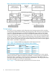
Table 22 The Relationship between Link Speed and Maximum Distance for Best Performance Link Speed Maximum Distance for Best Performance 1 Gbps 10 km 2 Gbps 6 km 4 Gbps 3 km 8 GbPS 2 km For best performance of distances that are larger than the distances described in Table 22 (page 55), HP recommends installing FC-SW. Figure 11 Remote Copy Connection Configurations For Fibre Channel interface connections, you can use the same switches as ordinary switch connections.
To properly support the configuration for setting the host mode options, ensure the use of the HP-approved extender. No. Host mode options When to select this option? 49 BB Credit Set Up Option 1*1*2 In XP Continuous Access and in cases where a long distance between M and R (approximately 100km) and a Switch is not used and in other cases, if the number of BB Credits controlling the amount of transfer data on Fibre must be tuned. Use by combining with host mode option 50.
NOTE: 1. Some switch vendors require an F port (for example, McData ED5000). 2.
To configure the MCUs and RCUs for XP Continuous Access Fibre Channel operations: 1. 2. 3. 4. 5. 6. Identify the volumes that will become the XP Continuous Access P-VOLs and S-VOLs. You need the storage system S/N, SSID, and CU of each XP Continuous Access volume to configure the MCUs and RCUs correctly for your desired pairs and async groups. When you create the pairs, you need the port, GID (host group ID), and LUN of each volume.
Figure 15 Configuring the RCU Target and Initiator Ports Configuring the MCUs and RCUs for XP Continuous Access Operations 59
Figure 16 Adding the RCUs 60 Preparing for XP Continuous Access Operations
Figure 17 Configuring the RCU Options Figure 18 Setting the Async Options Configuring the MCUs and RCUs for XP Continuous Access Operations 61
Figure 19 Adding the Consistency Groups 62 Preparing for XP Continuous Access Operations
4 Using the XP Continuous Access GUI This chapter describes the XP Continuous Access windows on Remote Web Console. XP Continuous Access Windows The XP Continuous Access windows (see Figure 20 (page 63)) display the XP Continuous Access information for the connected storage system and provide access to all XP Continuous Access functions and operations. The Quorum Disk Operation window is used with XP External Storage Access Manager Software.
The XP Continuous Access windows present six main windows: Pair Operation, RCU Operation, Asynchronous Operation, Usage Monitor, History, and System Option. Table 24 (page 64) shows the operations available for each window. To start the operations that you set on each XP Continuous Access function window, use the Apply button at the lower right of the XP Continuous Access window.
Table 24 XP Continuous Access Functions (continued) Window Menu Command Description Asynchronous Operation window CT Group Operation > CT Group Status Displays status information for existing consistency groups. (see “Asynchronous Operation Window” (page 76) CT Group Operation > Add CT Group Allows you to assign the consistency groups to the CUs. CT Group Operation > CT Group Option Allows you to change the consistency group options.
Figure 21 Pair Operation Window The Pair Operation window displays: Item Description Tree Displays the connected storage system, the LDKC, the CU grouping, the CUs, the ports, and the host groups. Select the desired CU grouping, CU ), port ( ), or host group to display the LUs for that CU grouping, ( CU, port, or host group. You can only select one CU grouping, CU, port, or host group at a time. List Displays the detailed LU information for the selected item (storage system, CU, or port).
Volume List The volume list on the Pair Operation window displays detailed information for each volume (LU) in the selected CU or port (or entire storage system when Subsystem is selected). You can sort the LUs in the volume list by selecting the column heading to sort on. Figure 22 (page 67) shows the volume list sorted by ascending port number. Select the column heading to change the sort order (ascending or descending).
Item Status Description : SMPL. The volume is not currently assigned to an XP Continuous Access pair. When the initial copy is started by a paircreate operation, the volume status changes to COPY. : COPY. The XP Continuous Access initial copy operation is in progress. Data on the pair is not fully identical. When the initial copy is complete, the status will change to PAIR. : PAIR. The volume is currently assigned to an XP Continuous Access pair, and the pair is synchronized.
Item Description Fence The P-VOL fence level of the XP Continuous Access pair: data, status, or never. See “Considering the P-VOL Fence Level Setting” (page 149) for a complete description of the P-VOL fence level option. Diff The differential data setting (bitmap table managed by cylinder or track). CTG Consistency group number (00-7F) of the pair (only for Synchronous-C pairs and Asynchronous pairs). ErrLyl Error level (group or LU) of the pair (only for Asynchronous pairs).
Figure 23 Display Filter Dialog Box The Display Filter Dialog box displays: 70 Item Description Port Allows you to select the port (or all ports) to be displayed or to enter the port number directly. You can specify the port number with two characters. For instance, you can abbreviate CL1-A as 1A. You can also enter the port number in both lowercase and uppercase characters. GID Allows you to select the GID (or all GIDs) to be displayed. GID means host group number.
Item Description Status Allows you to display only volumes that have the selected pair status: SMPL, COPY, PAIR, PSUS, PSUE, PDUB (LUSE only), Suspending (async only), Deleting (async only) and/or SSWS (XP External Storage Access Manager Software pair only). When PDUB is selected, simplex volumes are not displayed. Sub Status Allows you to select the consistency status of the Asynchronous pairs. Set button Applies your selections to the volume list and closes the Display Filter dialog box.
Figure 24 RCU Operation Window The RCU Operation window displays: 72 Item Description Display buttons Allows you to select either the MCU&RCU display (default) or Port display for the RCU Operation window. Tree When you select the MCU&RCU display with the Display button, the tree displays the CUs of the connected storage system. Select and double-click the desired CU to display the MCU/RCU information for that CU. Select the desired RCU to display the SSID and path information for that RCU.
Item Description Preview list When you select the MCU&RCU display with the Display button, the preview list displays the settings before you click the Apply button for adding or deleting RCU(s) or changing RCU options. To change or delete settings, right-click in the preview list. When you select the Port display with the Display button, the preview list displays the settings before you click the Apply button for changing the settings of port(s).
Double-click on the selected CU to display the RCU information for that CU (see “MCU&RCU Display on the RCU Operation Window showing RCU List ” (page 75)). If you select CU Free, the controller ID, model name, RCU serial number, LDKC number, and path group ID are displayed next to the RCU icon. If you select a CU number, the RCU serial number and CU number are displayed next to the RCU icon. You can double-click on an RCU of CU Free to display the path information for that RCU in the list.
Figure 26 MCU&RCU Display on the RCU Operation Window showing RCU List Port Display on the RCU Operation Window When the Port button is clicked in the Display box, the RCU Operation window displays the channel adapters (fibre: ) and port types (Target: , RCU Target: , Initiator: , External: , Initiator/External: ) in the tree and port information in the list. Select Subsystem to display all port information.
Figure 27 Port Display on RCU Operation Window Asynchronous Operation Window The Asynchronous Operation window (see Figure 28 (page 77)) allows you to perform the XP Continuous Access Asynchronous configuration operations (see “Asynchronous Operations” (page 102)). To update the information on the Asynchronous Operation window; • Click another tab, and then click the Asynchronous Operation tab. • Click File, and then Refresh on the menu bar of the Remote Web Console main window.
Figure 28 Asynchronous Operation Window XP Continuous Access Windows 77
The Asynchronous Operation window displays: Item Description Tree Allows you to display all consistency groups (except groups that are used for XP Continuous Access) belonging to LDKC#00 (default) or all consistency groups (except groups that are used for XP Continuous Access) belonging to LDKC#01. For each LDKC, this tree displays the consistency groups that are already in use (Used) and the consistency groups that are available for use (Not Used).
Figure 29 Usage Monitor Window The Usage Monitor window displays: Item Description Monitoring Switch Allows you to see whether monitoring is on or off. Monitoring Switch displays Enable when monitoring is on, and displays Disable when monitoring is off. When monitoring is stopped, the usage monitor graph is closed. The usage monitor graph can only be displayed when monitoring is running. Gathering Interval Allows you to see the data collection interval for usage monitoring.
information includes the records for the main status changes (for example, pair creation, and release) of the XP Continuous Access pairs. See “History Operations” (page 113) for information and instructions on performing XP Continuous Access history operations. To display the latest information for the History window, click File, and then Refresh on the menu bar of the Remote Web Console main window.
The History window displays: Item Description Status Displays the current status of the history file: • No history file exists: The history file does not exist. • Reading a history file failed: A failure occurred while referring to the history file. • Updating ... n (%): Updating the history file is now in progress. n (%) indicates the progress (in %) of the update process for the history file. • Complete: Updating the history file has been completed.
Item Description Previous and Next buttons The list displays up to a maximum of 16,384 operations at a time. Use these buttons to display the previous or next 16,384 operations. History List Displays the history information for the XP Continuous Access pairs in the connected storage system. XP Continuous Access history information is saved for seven days, and the maximum amount of information that can be saved is 524,288.
NOTE: • For XP Continuous Access pairs consisting of LUN Expansion (LUSE) volumes, the number of Pair Suspend (Failure) rows in the history list does not correspond to the number of LDEVs in the LUSE volume. For LUSE volumes with three or more LDEVs, only two rows showing Pair Suspend (Failure) are displayed. • Even if several errors occur at the same time, only two rows showing Pair Suspend (Failure) are displayed. • History information older than seven days is automatically deleted.
Item Description PreviewList Displays the settings before you click the Apply button for changing or deleting the settings. To change or delete settings, right-click in the preview list. Operation Displays the status of the process in progress. The following statuses of operation are displayed: • No Operation • Set the System Option • Set the CU Option 84 Apply button Applies the settings in the System Option window to the storage system.
5 Performing XP Continuous Access Configuration Operations This chapter provides instructions for performing XP Continuous Access configuration operations.
the appropriate XP Continuous Access settings and options for your operational environment and also by addressing conditions that can affect storage system performance. • Discontinuing XP Continuous Access operations. For “Discontinuing XP Continuous Access Operations” (page 118), you must perform the required operations (for example, pair release, RCU deletion, port re-configuration, etc.) in a specific order to ensure smooth operations and avoid command rejects and error conditions.
For the Port display, the menu commands are: • Initiator: Allows you to change the selected fibre port(s) to initiator ports. • RCU Target: Allows you to change the selected fibre port(s) to RCU targets. • Target: Allows you to change the selected fibre port(s) to target ports. For the MCU&RCU display, click the menu command for the desired operation. When two or more RCUs are selected, only the RCU Operation command is available.
Access software. For details on the port to which an initiator/external mix mode is set, see the HP StorageWorks XP24000/XP20000 External Storage Software User's Guide. IMPORTANT: Before changing a Fibre Channel port to an initiator port, disconnect the port from the host, release all affected XP Continuous Access pairs, delete all paths from the port to the MCU (if RCU target), and then remove all channel paths to the port.
Figure 32 Add RCU Dialog Boxes (Top: for CU Free, Bottom: Other than CU Free) RCU S/N: Allows you to enter the 5-digit serial number of the RCU being added. LDKC: Allows you to enter the LDKC number which the RCU belongs to. Specify 00 or 01. NOTE: You can specify only 00 for the current microcode version. Controller ID: Allows you to select the controller ID (storage system family ID) of the RCU being added from the drop-down list.
Logical Adr. (RCU CU): Allows you to enter the CU number of the RCU being added. The CU number differs by the specified controller ID as follows: • When the specified controller ID is 5 (XP24000/XP20000 disk array), you can select a CU number from 00 to FE. • When the specified controller ID is 4 (XP12000/XP10000 disk array), you can select a CU number from 00 to 3F. SSID: Allows you to enter the SSID(s) of the RCU being added.
8. 9. Verify the requested operation(s) displayed in the preview list. To change one or more operations, select the operation(s), right-click the preview list, and click Modify. To remove one or more operations, select the operation(s), right-click the preview list, and click Delete. To cancel all operations, select all the operations in the preview list, right-click, and click the Delete command, or click the Cancel button. To start the operation(s), click the Apply button.
Figure 33 Add RCU Operation − Fibre Channel Interface Changing the RCU Options The RCU Option dialog box (see Figure 34 (page 92)) allows you to set the RCU options for the connected MCU. The RCU options apply to all MCU CUs and to all RCUs connected to the MCU. The RCU Option dialog box is presented during the add RCU process, and can also be opened by right-clicking on the RCUs and clicking the RCU Operation > Change RCU Option command.
number, the MCU suspends all affected XP Continuous Access (and TrueCopy for Mainframe) pairs to prevent hosts from adversely affecting performance due to the inadequate number of paths. If you enter a number larger than the number of paths already set on the Add RCU dialog box, or if the number of paths falls below this number (for example, failed path), an error occurs.
Ask your carrier for the round trip time between the two sites where MCU and RCU storage systems are located. Alternatively, you may also use a router ping command to receive a rough estimate. If you discover you have very low round trip times, you may specify 1. The Initial copy response time is the response time required for multiple initial copy operations. You can use the following formula to get the initial copy response time.
4. Verify the requested operation(s) displayed in the preview list. To change the change RCU option operation, select the operation from the preview list, right-click, and click Modify. To remove the operation, select it, right-click, and click Delete. To cancel all operations, select all the operations in the preview list, right-click, and click the Delete command, or click the Cancel button. 5. To apply the settings, click the Apply button.
3. 4. 5. 6. 7. 8. Right-click the path and SSID list, and click Add Path to open the Add Path dialog box. On the Add Path dialog box, enter the new path(s). Click Set to close the Add Path dialog box. The preview list displays the requested add path operation(s). Verify the requested operation(s) displayed in the preview list. To change the add path operation, select the operation from the preview list, right-click, and click Modify.
Figure 36 Add SSID Dialog Box To add one or more SSIDs to an existing RCU: 1. 2. 3. 4. 5. 6. Click the RCU Operation tab, and click the MCU&RCU display button. Select and double-click on the desired MCU CU in the tree, and then select the RCU to which you want to add SSID(s). Alternatively, select the RCU in the list, right-click, and click Edit SSID(s) & Path(s). All SSIDs for the selected RCU are listed. Right-click the path/SSID list, and then click Add SSID to open the Add SSID dialog box.
Viewing RCU Status The RCU Status dialog box (see Figure 37 (page 99)) displays the detailed status information for the selected RCU. “Logical Path Status” (page 101) describes the path status descriptions. See “General Troubleshooting” (page 155) for troubleshooting information for MCU-RCU paths. To view the detailed RCU status information: 1. 2. 3. 98 Click the RCU Operation tab, and click the MCU&RCU display button. Select the RCU for which you want to display the status in the list.
Figure 37 RCU Status Dialog Box (Top: for CU Free, Bottom: for the CU excepting CU Free) RCU Operations 99
• Path List: ◦ No.: Path number (path list item number). ◦ Path Status: Path status. “Logical Path Status” (page 101) contains the path status descriptions. ◦ MCU Port: Port number of the MCU. ◦ RCU Port: Port number of the RCU. • RCU S/N: Serial number of the RCU. The LDKC number is displayed enclosed in parentheses to the right of the RCU S/N. • Controller ID: Controller ID and model name. • Path Gr. ID: The user-registered path group ID when an RCU is added to use CU Free.
• Round Trip Time: Delay time because of remote I/O according to the connection devices and the distance of the line between the MCU and RCU. • Check box, Refresh the RCU Operation window after this dialog box is closed: To refresh the RCU Operation window after closing the RCU Status dialog box, click the check box. By default, the check box is not selected. The Refresh button refreshes the status information. The Close button closes the RCU Status dialog box.
4. 5. 6. Right-click the RCU(s), click RCU Operation, and then click Delete RCU. When a confirmation message appears, click OK to delete the RCU, or click Cancel to cancel your request to delete the RCU. The preview list displays the requested delete RCU operation(s). Verify the requested operation(s) displayed in the preview list. To remove one or more operations, select the operation(s) from the preview list, right-click, and click Delete.
Setting the Asynchronous Copy Options The Async Option dialog box (see Figure 38 (page 103)) allows you to set and modify the XP Continuous Access Asynchronous copy option parameters for the connected storage system. To open the Async Option dialog box, right-click the CT groups, and click the Async Option command. The async options apply to the entire physical control unit, including all XP Continuous Access P-VOLs and S-VOLs behind the control unit.
cache that is used for async recordsets reaches the specified value of the threshold, the MCU controls the cache inflow. It follows that the delay of I/O time of MCU occurs. The I/O Delay Increase option allows you to specify the threshold (30-70%), which is the maximum amount of cache for starting to strengthen control over the inflow for the asynchronous copy. When the amount of cache that is used for async recordsets reaches the specified value of the threshold, the MCU controls the cache inflow.
Figure 39 Add CT Group Dialog Box MCU-RCU Path: Indicates the path type (fibre) for the remote copy connections. Currently, you cannot change the path type. Offloading Timer (sec.): Allows you to specify the amount of time for monitoring the transfer of data to a sidefile between 0 and 255 seconds in 1 second increments. The default setting is 90 seconds. Enable Inflow Control: Allows you to enable the inflow control. To enable the inflow control, click the check box. By default, the check box is selected.
7. Verify the requested operation(s) displayed in the preview list. To change one or more operations, select the operation(s) from the preview list, right-click, and click Modify. To remove one or more operations, select the operation(s) from the preview list, right-click, and click Delete. To cancel all operations, select all the operations in the preview list, right-click, and click the Delete command, or click Cancel button. 8. To start the operation(s), click the Apply button.
To change the group options for one or more groups: 1. 2. 3. 4. 5. 6. 7. Make sure that all pairs in the group(s) have been split (Pairsplit-r), so that you can change the group options. See “Splitting XP Continuous Access Pairs” (page 133) for instructions on splitting pairs. Select the LDKC where the desired consistency group belongs, or select Used from the tree in the Asynchronous Operation tab to display the existing consistency groups in the list.
Figure 41 CT Group Status Dialog Box • CT Group: Group number of the selected consistency group. • This CU Type: CU type (MCU or RCU) of the selected consistency group. • LDKC: The number of the LDKC where the consistency group belongs. • CLPR: The number and name of the CLPR to that the volumes forming pairs belong. • S/N, ID: Serial number and SSID of the CUs or Path Gr. of the selected consistency group. The LDKC number is also displayed enclosed in parentheses to the right of the CU number.
group. The Refresh button refreshes the status information. The Close button closes the CT Group Status dialog box. Deleting Consistency Groups A consistency group can be deleted only from the MCU and only if the MCU does not contain any P-VOLs still assigned to the group. Deleting a consistency group from an MCU does not affect the consistency groups registered at other MCUs. The RCU automatically deletes a consistency group when the last pair in the group is released.
y-axis varies according to the maximum value of the statistical data that is displaying. If the value on the y-axis exceeds 10,000,000, the value is displayed in exponential notation (for example, 1E7 = 1×107 = 10,000,000; 2E8 = 2×108 = 200,000,000). The Update field displays the most recent data sample time for the data on the graph. To display the usage monitor graph: 1. 2. 3. Make sure that usage monitoring is running (Monitoring Switch = Enable).
NOTE: The host group name will be indicated in up to 8 characters at the top of the graph if the Normal Size command is clicked. To check the host group name, magnify the graph. During the asynchronous copy operation, LDEVs that issue RIOs are not fixed. The number of RIOs displayed is the total for all consistency groups. To specify the LDEVs, use Performance Monitor. For further information on Performance Monitor, see the HP StorageWorks XP24000/XP20000 Performance Monitor User's Guide.
Table 28 Remote Copy I/O Statistics (continued) Statistic 1 Description RIO error count Number of errors that occur during remote I/O. Initial copy Initial copy RIO count Number of initial copy remote I/Os. Average transfer rate (kB/s) Average transfer rate (kB/sec) for initial copy remote I/Os. Average response (ms) Average response time (msec) for initial copy remote I/Os. Update copy Update copy RIO count Number of update copy remote I/Os.
Table 28 Remote Copy I/O Statistics (continued) Statistic 1 Description Number of Remaining Recordsets Number of remaining recordsets when the schedule is completed. Scheduling Attempt Count Number of job activations of consistency manager. Synchronization2 Pair Synchronized (%) Percent completion of initial copy operations (that is, number of synchronized pairs / total number of pairs).
(4) This column is not used. (5) LDKC number, CU number, and LDEV number of the paired volume. (6) The time taken for the operation (from the start of the operation to the end). Displayed only for Pairing Complete and Pair Resync. Complete operations.
5. 6. Verify the desired change(s) in the preview list. • To change the settings, right-click the preview list, click Modify, make the desired changes, and close the dialog box. The preview list displays the updated information. • To omit the settings, right-click the preview list, and click Delete. The changes are cancelled. • To cancel all operations, select all the operations in the preview list, right-click, and click the Delete command, or click the Cancel button. The changes are cancelled.
Figure 45 Option Settings List for the CUs • CU: Number of CUs in the LDKC that you chose from the tree (00 to FE). • Activities: Number of volumes in concurrent initial copy operations (1 to 16). When you set Disable for the Maximum Initial Copy Activities(CU) option on the System Option dialog box, Disable is shown instead of a number.
Figure 46 CU Option Dialog Box Maximum Initial Copy Activities: Allows you to specify the number of volumes on which copy operations can be performed at the same time, from 1 to 16 volumes, for the selected CU. Even if you set a value larger than the setting for Maximum Initial Copy Activities on the System Option dialog box, the priority is given to Maximum Initial Copy Activities on the System Option dialog box.
Table 29 Optimizing XP Continuous Access Operations and Storage System Performance Condition Description Recommendation(s) Write-intensive workloads Write-intensive workloads, such as database logging volumes, can have a significant impact on storage system I/O response times. Spread write-intensive data across several volumes to minimize queuing. Large block size Workloads with large write block sizes, such as DB deferred writes, can impact performance.
2. 3. 4. 5. use the Delete Range-Group option to release all pairs in a group using just one operation. Verify that the pair status has changed to SMPL for all XP Continuous Access volumes before continuing. Delete the XP Continuous Access Asynchronous group(s) from the MCU(s) . The RCU automatically deletes a group when all pairs in the group have been released. Delete the RCUs (see “Deleting an RCU” (page 101)). Check each CU of each MCU to make sure that all RCUs have been deleted before continuing.
6 Performing XP Continuous Access Pair Operations This chapter provides instructions for performing XP Continuous Access pair operations • “Preparing for XP Continuous Access Pair Operations” (page 120) • “Pair Operation Window” (page 121) • “XP Continuous Access Snapshot Function” (page 122) • “Creating XP Continuous Access Pairs” (page 123) • “Initial Copy Options” (page 127) • “Pair Options” (page 128) • “Changing Pair Options” (page 129) • “Viewing XP Continuous Access Pair Status” (page
You can start creating the XP Continuous Access pairs as soon as you have: • Identified the volumes (LUs) that will become the XP Continuous Access P-VOLs and S-VOLs • Ensured that all system and XP Continuous Access requirements have been met • Completed hardware and software installation • Configured the MCUs and RCUs for XP Continuous Access operations If you will be using the XP Continuous Access software to perform XP Continuous Access operations, the MCU of each XP Continuous Access pair must
Pairsplit-r: Allows you to split (suspend) pairs. Pairresync: Allows you to resynchronize pairs. Change Pair Option: Allows you to change the pair options. The availability of the commands (enabled/disabled) depends on the status of the LU(s) or pair(s) selected in the list. 4. 5. 6. Click the command for the desired operation, use the dialog box to perform the operation, and close the dialog box. The preview list displays the requested operation(s). Verify the specified pair operation(s).
Example of an XP Continuous Access Snapshot File The following is an explanation of the fields: (1) Port number (2) GID and host group name (3) LU number (4) LDEV number (5) Status of the pair (6) Suspend sub status (7) Serial number of other CU (8) Other CU SSID or Path Group ID (9) Port number of other LU (10) GID of other LU (11) LU number of other LU (12) LDEV number of other LU (13) Pair mode (14) Fence level (15) Differential data setting (16) Consistency group number (17) Error level (18) Copy prio
Figure 48 Paircreate Dialog Box for Synchronous Pairs Figure 49 Paircreate Dialog Box for Asynchronous Pairs 124 Performing XP Continuous Access Pair Operations
• P-VOL: Displays the port number, GID, LUN, CLPR number, and CLPR name of the selected LU(s). If you selected more than one P-VOL, the P-VOL with the lowest LUN is displayed. If the pound or gate symbol (#) is added to the end of the device ID (00:00:3C #, for example), the LDEV is an external volume. For details on external volumes, see the HP StorageWorks XP24000/XP20000 External Storage Software User's Guide.
• Difference Management: Select Auto, Cylinder, or Track as the basis for managing the differential data. The default setting is Auto. When you select Auto, either Cylinder or Track is selected depending on the basic size of the logical unit (LU). This option cannot be changed after a pair has been added. • Asynchronous Parameters (async only): ◦ CT Group: Consistency group for the new pair(s). Consistency groups that have already been added to the current MCU are displayed.
7. 8. 9. Select the desired initial copy options and pair options for the pair(s) being created. The initial copy options and pair options you select are applied to all pairs being created, and you can modify the options for each pair as needed before starting the paircreate operations (see step 9). Click Set to close the Paircreate dialog box. The requested paircreate operations are displayed in the preview list. Verify the requested operation(s) displayed in the preview list.
but may affect the storage system’s I/O performance if the P-VOL is experiencing high write I/O activity. A lower setting (for example, 3 tracks) slows down the initial copy operation to minimize the impact of the initial copy operation on the storage system’s I/O performance. Priority: Specifies the order in which the initial copy operations will be performed, if the number of requested initial copy operations is greater than the maximum initial copy activity setting on the System Option window.
suspended, subsequent write operations to the P-VOL will be accepted, and the MCU will keep track of all P-VOL updates while the pair is suspended. CT Group (Asynchronous only): Specifies the consistency group number for new pairs. All XP Continuous Access Asynchronous pairs must be assigned to a consistency group. To change the consistency group to which a pair is assigned, you must release and then restart the pair with the desired group selected.
If an X mark is added to the end of the device ID (00:00:3C X, for example), the LDEV that the number indicates is a Thin Provisioning virtual volume. For details on virtual volumes, see the HP StorageWorks XP24000/XP20000 Thin Provisioning Software User's Guide. • • P-VOL Fence Level: Select the fence level for the new pair(s). The fence level determines the conditions under which the MCU will reject write operations to the P-VOL. Never is automatically set for an asynchronous pair.
Viewing XP Continuous Access Pair Status The Detailed Information dialog box (see Figure 51 (page 131)) displays the detailed pair status information for the selected pair. To open the Detailed Information dialog box, click the Pair Operation tab, select a CU grouping, CU, port, or host group from the tree, select the desired pair, right-click, and then click the Detailed Information command.
circumstances, do not change or delete the port number, the host group number, or LUN that you specified when creating the pair. CLPR: The CLPR number and the CLPR name of the volume on the primary site are displayed. Group Name: Displays the host group name if the port on the primary site connects a host group. Pair Status: SMPL, COPY, PAIR, PSUE, PSUS, PDUB, Suspending, Deleting, or SSWS. For information on the Pair Status, see “Pair Status” (page 31).
Asynchronous Parameters • CT Group: Consistency group that the XP Continuous Access Asynchronous repair is assigned to. • Error Level: Error level of the XP Continuous Access Asynchronous Software (Group or Volume). • Check box, Refresh the Pair Operation window after this dialog box is closed: To refresh the Pair Operation window after closing the Detailed Information dialog box, click the check box. By default, the check box is not selected.
Figure 52 Pairsplit-r Dialog Box (Synchronous and Asynchronous) The pairsplit options are: • Volume: Port - GID - LUN of the selected volume. If the pound or gate symbol (#) is added to the end of the device ID (00:00:3C #, for example), the LDEV is an external volume. For details on external volumes, see the HP StorageWorks XP24000/XP20000 External Storage Software User's Guide.
merged at the MCU. This option is available only when the selected volume is an XP Continuous Access P-VOL. ◦ • • Disable: The S-VOL of this pair only accepts read I/Os while the pair is split. Suspend Kind (default = S-VOL): ◦ S-VOL: The P-VOL accepts all subsequent write I/O operations, and the MCU keeps track of updates while the pair is split. Subsequent write I/O operations to the P-VOL will be accepted or rejected depending on the fence level of the pair.
1. Connect to the MCU or RCU of the pair(s) to be split, open the XP Continuous Access main window, and click the Pair Operation tab. You do not need to vary the P-VOL(s) offline. To use Enable for S-VOL Write option, you must connect to the MCU and select the P-VOL of the pair(s). 2. 3. In the tree, select the port, host group, desired CU, or the upper CU grouping. In the list, select the XP Continuous Access pair(s) that you want to split.
Resynchronizing XP Continuous Access Pairs While an XP Continuous Access pair is split or suspended, the MCU does not perform any update copy operations to the S-VOL. • For a split/suspended XP Continuous Access Synchronous pair, the MCU may or may not continue accepting write I/Os for the P-VOL depending on the P-VOL fence level pair option and suspend kind pairsplit option (if user-requested) .
Figure 53 Pairresync Dialog Box for Synchronous and Asynchronous The pairresync options are: • P-VOL: Port - GID - LUN of the selected volume. If the pound or gate symbol (#) is added to the end of the device ID (00:00:3C #, for example), the LDEV is an external volume. For details on external volumes, see the HP StorageWorks XP24000/XP20000 External Storage Software User's Guide.
If an X mark is added to the end of the device ID (00:00:3C X, for example), the LDEV that the number indicates is a Thin Provisioning virtual volume. For details on virtual volumes, see the HP StorageWorks XP24000/XP20000 Thin Provisioning Software User's Guide. • P-VOL Fence Level (Sync only): If desired, you can change the fence level of the pair(s). See “Pair Options” (page 128) for further information on the fence level pair option.
as modified, so that the MCU will perform the equivalent of an entire initial copy operation when the pairs are resynchronized. If you select a pair from the volume list and change the settings, and if you use a drop-down list to set blank to a parameter, the parameter takes the default value for each pair.
MCU, the MCU stops all update copy operations for that pair and changes the pair status of the P-VOL and S-VOL to SMPL. After an XP Continuous Access pair is released, the MCU continues to accept all subsequent write I/O operations to the P-VOL and will not keep track of the P-VOL updates. An XP Continuous Access pair should be released from the RCU only for disaster recovery (see “Usage Scenarios” (page 147)).
NOTE: If you select a pair from the volume list and change the settings, and if you use a drop-down list to set blank to a parameter, the parameter takes the default value for each pair. If you select the settings from the preview list before applying the changed settings, and if you use a drop-down list to set blank to a parameter in the Pairsplit-S dialog box, the parameter value in the preview list will not be changed.
Delete Pair by Force: • Yes: The pair(s) will be released even if the MCU is unable to communicate with the RCU. This option may be used to free a host waiting for a device-end from an MCU that cannot communicate with its RCU, thus allowing host operations to continue. • No: The pair(s) will only be released if the MCU is able to change the pair status of the P-VOL and S-VOL to SMPL. When the status of the pair(s) to be released is SMPL or Deleting, the default setting is Yes (which cannot be changed).
1. Connect to the MCU or RCU* of the pair(s) to be released, open the XP Continuous Access main window, and click the Pair Operation tab. If you plan to use the C/T Delete Range option, you must connect to the RCU. 2. 3. In the tree, select a port, host group, desired CU, or upper CU grouping. Use the Display Filter as needed to display the desired pairs (for example, select Async only) (see “Display Filter” (page 69)). In the list, select the pair(s) that you want to release.
generate SIMs reporting the failures. The MCU will change the status of the P-VOLs to suspended-by RCU but will not be able to change the status of the S-VOLs. If an MCU/RCU is powered off and its backup batteries are fully discharged while XP Continuous Access pairs are suspended, the P-VOL/S-VOL differential data will not be retained.
5. 6. Power on the RCU(s). Make sure that they are fully operational and ready to resynchronize operations before powering on the MCUs. Power on the MCU(s), and make sure that they are ready to resynchronize operations. If you split any pairs in step 3, you can also resynchronize (pairresync) those pairs now. Pinned Track Recovery for XP Continuous Access Volumes To ensure full data integrity of the pair while recovering the pinned track, use the following procedure: 1. 2.
7 Usage Scenarios This chapter describes several usage scenarios for XP Continuous Access. • “Data Migration Using XP Continuous Access Synchronous” (page 147) • “Point-in-Time (PiT) Data Duplication Using XP Continuous Access Asynchronous” (page 148) • “Using XP Continuous Access for Disaster Recovery Operations” (page 148) Contact your HP service representative for further information on Business Continuity and Disaster Recovery Solutions from HP.
d. e. To keep the volumes synchronized, establish the same XP Continuous Access pair(s) in the reverse direction using the None initial copy option (see “Initial Copy Options” (page 127)). If the original P-VOL(s) will be temporarily unavailable for update copy operations, you can split the new pair(s) (pairsplit-r) so that the new MCU keeps track of the changes. Start the applications with the S-VOL(s).
3. Use the appropriate combination of XP Continuous Access options for disaster recovery: • XP Continuous Access Asynchronous offloading timer option and Time Out (Copy Pending) group option. The Time Out (Copy Pending) group option can be used to limit the time duration during which updates may be lost. The offloading timer value should be less than the HBA timeout value.
P-VOL, but the MCU keeps track of updates to the P-VOL while the pair is suspended. Host failover capability is essential if this fence level setting is used. For disaster recovery, the currency of the S-VOL is determined by using the sense information transferred via host failover or by comparing the S-VOL contents with other files confirmed to be current.
example, database journal log file that was active at the primary system when the disaster occurred). The XP Continuous Access Asynchronous consistency status (group or volume) can be useful when performing this detection and retrieval. Since this detection/retrieval process can take a while, your disaster recovery scenario should be designed so that detection/retrieval of lost updates is performed after the application has been started at the secondary system.
Analyzing the Currency of XP Continuous Access Synchronous S-VOLs Table 32 (page 152) shows how to determine the currency of an XP Continuous Access Synchronous S-VOL based on its pair status and P-VOL fence level setting. For XP Continuous Access Synchronous pairs with a P-VOL fence level setting of Never, further analysis is required to determine the currency of these S-VOLs.
Table 33 Analyzing the Consistency of XP Continuous Access Asynchronous S-VOLs Status of S-VOL Consistency Status Usable for Recovery? Description PAIR -- No These states do not usually occur during XP Continuous Access Asynchronous disaster recovery because the RCU suspends all XP Continuous Access Asynchronous S-VOLs when communication with the MCU is lost. XP Continuous Access Asynchronous S-VOLs in these states should not be used for disaster recovery.
8. to send XP Continuous Access remote copy operations to the original MCUs to bring the original P-VOLs up to date. At the remote site, establish the same XP Continuous Access Asynchronous groups and XP Continuous Access pairs in the reverse direction to synchronize the original P-VOLs with the S-VOLs. Make sure to use the Entire Volume initial copy option.
8 Troubleshooting General Troubleshooting Table 34 (page 155) provides general troubleshooting information for XP Continuous Access. “Troubleshooting RCU Path Status Problems” (page 156) provides troubleshooting information for RCU paths. “Troubleshooting Suspended XP Continuous Access Pairs” (page 158) provides troubleshooting information for suspended XP Continuous Access pairs (Synchronous and Asynchronous).
Table 34 General XP Continuous Access Troubleshooting (continued) Error Corrective Action Paircreate or pairresync operation resulted in Hardware failure: If the timeout error was caused by a a timeout error. hardware failure, a SIM will be generated. If this occurs, call your HP service representative, and retry the XP Continuous Access operations after the problem is fixed.
Table 35 Troubleshooting RCU Path Status Problems (continued) Path Status Description Corrective Action Resource Shortage (MCU/RCU) The MCU/RCU rejected the establish logical path link control function because all logical path resources in the MCU/RCU are being used for other connections. Delete the failed path, and also delete all paths and RCUs not currently in use. The MCU can be connected to up to four RCUs with up to eight paths to each RCU.
Table 35 Troubleshooting RCU Path Status Problems (continued) Path Status Description Corrective Action Communication Failed The MCU connected to the RCU successfully, but a logical communications timeout occurred. Make sure that the RCU port and remote copy connection hardware (cables and switches) are properly configured and functioning. Logical Blockade The MCU port does not work. Repair the port status on the MCU. The RCU port does not work. Repair the port status on the RCU.
Table 36 Troubleshooting Suspended XP Continuous Access Pairs (continued) Pair Applies to Description Status/Type Corrective Action PSUE / MCU IMPL P-VOL, S-VOL The MCU could not find valid control information in its nonvolatile memory during the IMPL procedure. This error occurs only if the MCU is without power for more than 48 hours (for example, power failure or fully discharged batteries). Resynchronize the pair (Pairresync) from the MCU.
Table 37 Resolving XP Continuous Access Asynchronous Suspension Conditions Classification Causes of Suspension SIM MCU/RCU hardware Hardware redundancy has been lost due DB0x to some blockade condition. As a result, DB1x MCU-RCU communications, creating or DB2x receiving recordsets, or the staging or de-staging process could not complete. Recovery procedure According to the SIM, remove the hardware blockade or failure. Re-establish failed pairs (pairresync).
Figure 56 XP Continuous Access Error Message for a Failed Delete RCU Operation The Delete RCU failed because the RCU still contains one or more pairs with the current MCU. Troubleshooting When Using RAID Manager When an error has occurred in XP Continuous Access Software pair operation using RAID Manager, you might identify the cause of the error by referring to the log displayed on the RAID Manager window or in the RAID Manager operation log file.
Table 38 Error Code and Error Contents When Operating RAID Manager Error Code (SSB1) B901 Error Code (SSB2) Error Content 4A96 A request for XP Continuous Access Paircreate was received. However, the command was rejected because the specified P-VOL belongs to the different CLPR from the CLPR for the consistency group that is already registered.
Table 38 Error Code and Error Contents When Operating RAID Manager (continued) Error Code (SSB1) Error Code (SSB2) Error Content C189 A request for Pairsplit-S was received. However, the command was rejected because the pair status was invalid. C18A A request for Pairsplit-S was received. However, the command was rejected because the corresponding volume was changing the status or the group included the pair in process of status change.
Table 38 Error Code and Error Contents When Operating RAID Manager (continued) Error Code (SSB1) 164 Troubleshooting Error Code (SSB2) Error Content C23D The command was rejected because the command for XP Continuous Access Synchronous was issued to the XP Continuous Access Asynchronous volume. C267 Pair cannot be created because the command was issued to the command device. C271 The command was rejected because the specified consistency group number is invalid.
Table 38 Error Code and Error Contents When Operating RAID Manager (continued) Error Code (SSB1) Error Code (SSB2) Error Content C31A The P-VOL is in the process of collection access. C31B The P-VOL is blocked. C31C The P-VOL is blocked and impossible to access. C31D The P-VOL is in the process of format. C31E The P-VOL is for read only. C320 The number of MCU-RCU logical paths is 0 (for example, not specified).
Table 38 Error Code and Error Contents When Operating RAID Manager (continued) Error Code (SSB1) 166 Troubleshooting Error Code (SSB2) Error Content C33F The corresponding volume cannot be specified as S-VOL because the volume is already specified as XP Continuous Access pair volume. C35C The P-VOL is not accessible. C370 The number of paths is smaller than the number of minimum paths that are required to be specified because of the path failure or specifying the invalid path.
Table 38 Error Code and Error Contents When Operating RAID Manager (continued) Error Code (SSB1) Error Code (SSB2) C3BA Error Content A request for Paircreate was received. However, the command was rejected because of one of the following reasons: • The specified RCU’s SSID or CU number is not supported. • Though the specified RCU’s SSID or CU number is supported, the microcode for the MCU device does not support them.
Table 38 Error Code and Error Contents When Operating RAID Manager (continued) Error Code (SSB1) 168 Troubleshooting Error Code (SSB2) Error Content CB21 In Pairresync, all difference setting was abnormally terminated. CB5C (When connected to XP1024/XP128 Disk Array series) the port number and the LUN exceed the range that can be set by the series. CB5D (When connected to XP1024/XP128 Disk Array series) the LUN and the device number exceed the range that can be set by the series.
Table 38 Error Code and Error Contents When Operating RAID Manager (continued) Error Code (SSB1) Error Code (SSB2) Error Content CBE0 Paircreate cannot be executed because the P-VOL is a virtual volume for XP Snapshot. CBE1 Paircreate cannot be executed because the S-VOL is a virtual volume for XP Snapshot. CBE2 Paircreate cannot be executed because the P-VOL is a Pool-VOL for XP Thin Provisioning. CBE3 Paircreate cannot be executed because the S-VOL is a Pool-VOL for XP Thin Provisioning.
• The exact content of any error messages displayed by Remote Web Console. • The Remote Web Console configuration information (use the FD Dump Tool). • The service information messages (SIMs), including reference codes and severity levels displayed by Remote Web Console. For worldwide technical support information, see the HP support website: http://www.hp.
9 Support and Other Resources Related Documentation • HP StorageWorks XP24000/XP20000 Disk Array Owner Guide • HP StorageWorks XP24000/XP20000 Remote Web Console User Guide • HP StorageWorks XP24000/XP20000 RAID Manager User Guide • Hitachi TrueCopy™ for Mainframe User's Guide: HP XP24000 Disk Array, HP XP20000 Disk Array • HP StorageWorks XP24000/XP20000 LUN Manager User Guide • HP StorageWorks XP24000/XP20000 Remote Web Console Error Codes • HP StorageWorks XP24000/XP20000 for Compatible Exte
• Error messages • Operating system type and revision level • Detailed questions Subscription Service HP recommends that you register your product at the Subscriber’s Choice for Business website: http://www.hp.com/go/e-updates After registering, you will receive email notification of product enhancements, new driver versions, firmware updates, and other product resources. HP Websites For additional information, see the following HP websites: • http://www.hp.com • http://www.hp.
A XP Continuous Access Load Balancing and Sidefile Management and Control Asynchronous Remote Copy solutions, as applicable to Disaster Recovery (DR), protect operational environments by assuring data integrity and rapid recovery at an alternate location should the operational environment at the home site be disrupted. As with any implemented application or solution, impact to the operational environment must be minimal.
1. 2. 3. 174 Allow direct control of the host impact metrics using a methodology called Load Balancing. Load balancing allows management of the thresholds for inducing host delay and for the degree of induced delay. Use XP Business Copy to provide a tertiary Point-in-Time (PiT) copy in support of the DR/BC requirements. The PiT copy may be manually controlled at specified times or be automated on a continuing interval basis using XP RAID Manager.
B Retention of Pair Consistency using the Consistency Group of the XP Continuous Access Synchronous To maintain pair consistency within the storage system, it is possible to do the following: • Automatic Registration for the Consistency Groups When creating an XP Continuous Access Synchronous pair using the Remote Web Console, the created XP Continuous Access Synchronous pair can be registered in a specific consistency group automatically.
Changing the Status of S-VOL When the RCU is Disconnected When RCU detects that all of the connections for MCU are disconnected, all the XP Continuous Access Synchronous S-VOLs registered in CTG Number 127 will be changed to PSUE status. The following details apply to this feature: 176 • S-VOLs can be changed to PSUE status only when the Function Switch 30 is set on the RCU. • Only XP Continuous Access Synchronous S-VOLs registered in CTG Number 127 will be changed to PSUE status.
Glossary A ADDR, Adr Address. A data structure or logical convention used to identify a unique entity, such as a particular process or network device. ATM Asynchronous transfer mode. C C/T Consistency time. CHA Channel adapter. A device that provides the interface between the array and the external host system. Occasionally, this term is used synonymously with the term channel host interface processor (CHIP). CKD Check key data. An IBM file structure standard for disk volumes.
N NVS Nonvolatile storage. P P-VOL Primary volume. P/K Package. PCB Printed circuit board. PSUE Pair suspended-error. PSUS Pair suspended-split. R RAID1/5 Specific RAID architectures. RC Reference code. RCU Remote control unit. RDC Remote dual copy. Also known as remote copy. RIO Remote I/O. ROT Rules of Thumb. S S# Serial number. Also known as S/N. S-VOL Secondary or remote volume. The copy volume that receives the data from the primary volume. S/N Serial number.
Index C H cache inflow control, 23 requirements for XP Continuous Access, 52 communication time out (RCU status), 156 components, 9 Concurrent Copy, 24 configuring MCUs and RCUs for XP Continuous Access, 57 consistency group, 13, 30 operations on groups, 30 options, 30 requirements, 52 Consistency Groups automatic registration, 175 consistency status, 34 control units (CUs), 11 conventions storage capacity values, 171 COPY (pair status), 32 copy mode, 17 CTG Number 127, 175 CU, 12 currency of S-VOLs, 152
Performance Monitor, 46 pinned track, 146 point-in-time copy, 148 powering off/on XP Continuous Access components, 144 PSUS, PSUE (pair status), 32 R RCU powering off/on, 144 RCU port number mismatch (RCU status), 157 RCU ready timeout (group option), 30 RCU target port, 15 read and write I/O operations, 16, 18 recordset operations, 21 related documentation, 171 remote copy connections, 14 remote copy operations initial copy, 16 update copy, 17 remote I/O (RIO) operation, 21 Remote Web Console, 15 Remote W