HP XP24000/XP20000 LUN Manager User Guide Abstract This guide explains how to define paths between hosts and logical volumes, a prerequisite for storing data on an HP XP24000/XP20000 storage system. Other topics include configuring ports, controlling host access to volumes, specifying command devices, and using spreadsheets to configure the storage system.
© Copyright 2007, 2011 Hewlett-Packard Development Company, L.P. Confidential computer software. Valid license from HP required for possession, use or copying. Consistent with FAR 12.211 and 12.212, Commercial Computer Software, Computer Software Documentation, and Technical Data for Commercial Items are licensed to the U.S. Government under vendor's standard commercial license. The information contained herein is subject to change without notice.
Contents 1 Overview of LUN Manager Operations.........................................................6 Overview of LUN Manager........................................................................................................6 Overview of LUN Security..........................................................................................................6 2 About LUN Manager Operations..................................................................7 Overview of LUN Manager Operations..............
Enabling or Disabling Host Authentication........................................................................49 Registering Host User Information....................................................................................49 Changing Host User Information.....................................................................................51 Deleting Host User Information........................................................................................
Setting the Host Group.......................................................................................................96 Setting the WWN Information.............................................................................................98 Setting the LU Path.............................................................................................................98 Configuring the Command Devices......................................................................................
1 Overview of LUN Manager Operations This chapter provides a very brief overview of the LUN Manager functions. • Page 6 • Page 6 Unless otherwise specified, the term storage system in this guide refers to the following disk arrays: • HP XP24000 Disk Array • HP XP20000 Disk Array The GUI illustrations in this guide were created using a Windows computer with the Internet Explorer browser. Actual windows may differ depending on the operating system and browser used.
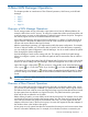
2 About LUN Manager Operations This chapter provides an introduction to Fibre Channel operations, LUN Security, and HP RAID Manager. • Page 7 • Page 7 • Page 9 • Page 10 Overview of LUN Manager Operations The HP storage system can be connected to open-system server hosts of different platforms (for example, UNIX servers and PC servers). To configure a system that includes open-system hosts and a storage system, you must use LUN Manager to configure logical volumes and ports.
1A and three Windows hosts are connected to port 1B, you cannot register all five Windows hosts in one host group. You must register the first two Windows hosts in one host group and then register the remaining three Windows hosts in another host group. After server hosts are classified into host groups, you must associate host groups with logical volumes. In (page 8), the host group hg-lnx is associated with three logical volumes (00:00:00, 00:00:01, and 00:00:02).
the host. You do not need to restart the system when you add, change, or delete LU paths with LUN Manager. If a hardware failure (such as a CHA failure) occurs, there is a chance that some LU paths will be disabled and some I/O operations stopped. To avoid such a situation, the system administrator can define alternate LU paths; if one LU path fails, the alternate path takes over the host I/O. For instructions on how to define LU paths, see (page 29).
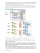
Usually, you do not need to disable LUN security on ports. If LUN security is disabled on a port, the connected hosts will only be able to access LUs associated with host group 0 (zero), and will be unable to access LUs associated with any other host group. Figure 3 Disabling LUN Security The host group 0 is the only host group reserved for each port by default.
• Virtual volumes for HP XP Snapshot Software • Reserve volumes for Data Retention Utility • XP Continuous Access Journal volumes • System disks • Journal volumes • Pool volumes • Remote command device • Quorum disks Configuring LUs for Use by RAID Manager 11
3 Preparing for LUN Manager Operations This chapter describes the system requirements, instructions for configuring Remote Web Console, enabling the required software, and notes on using LUN Manager.
4 Using the LUN Manager GUI This chapter describes the windows in the LUN Manager GUI. • Page 13 • Page 18 • Page 23 • Page 25 Fibre Channel Windows LUN Manager Window When you launch LUN Manager, the LUN Manager window appears. The LUN Manager window lets you define LU paths and apply LUN security to logical volumes. The storage partition administrators can display information or perform the operation within only the allocated SLPR (storage management logical partition).
Item Description WWN list The WWN list is available when you select an item related to a Fibre Channel port from the tree. For details, see (page 16). LDEV list This table provides information about the logical volumes in the storage system. For details, see (page 17). Other components in this window are explained in later sections. LU Path Tree Use this tree to find information about LU paths.
When you double-click a port for which LUN security is disabled, the host groups, except for the first host group (host group 0), are unavailable. LU Path List On the right side, a table displays LU path information about the host group specified in the tree. Figure 6 LU Path List Item Description LUN LUNs assigned to logical volumes. LUNs are address numbers assigned to LUs, which are logical volumes that can be accessed by open-system hosts.
Item Description Capacity Size of each logical volume. RAID RAID level for each logical volume. If the logical volume is an external volume or a virtual volume, the RAID column does not show the RAID level, but shows a hyphen (-) instead. When the parity groups are combined, an asterisk (*) and a number appear on the right of the RAID level. For example, 5(7D+1P)*2 indicates that two parity groups are combined. Paths Number of alternate paths, if any.
Figure 7 WWN List The WWN list provides information about host bus adapters that are connected to Fibre Channel ports of the storage system. Item Description Port A list of ports. The Fibre address of a port appears to the right of the port name. Host Group Host groups, which are used to classify server hosts connected to the storage system. Create host groups in the LUN Manager window. Name Nicknames of host bus adapters. Nicknames can be specified in the LUN Manager window.
Item Description If an LDEV number ends with #, the logical volume is an external volume. If an LDEV number ends with V, the logical volume is a virtual volume for XP Snapshot. If an LDEV number ends with X, the logical volume is a virtual volume for XP Thin Provisioning. UUID ID of a logical volume from the host. If a UUID is not specified, this column becomes blank.
Figure 9 Port Window (When Selecting Icon under Fibre Folder) Item Description Package tree Select a port to be operated in this tree. For details, see (page 19). Port list Shows all ports on a channel adapter if you select a channel adapter in the tree, or all ports in a port block if you select a port block. Use the options in the Change Port Mode group box to change information in this list. For details, see (page 20). Change Port Mode box Use this box to change information in the Port list.
Figure 10 Package Tree When you double-click the Fibre folder, the folder opens and lists Fibre Channel adapters (CHAs). When you double-click a channel adapter, port blocks appear below the channel adapter. The meaning of the icons of the channel adapters and the port blocks is shown here: Icon Description Indicates a channel adapter package. All ports in this channel adapter package are in Standard mode. Indicates a channel adapter package.
Figure 11 Port List Displaying Information about Fibre Channel Ports Item Description Port Name Port names. For details, see (page 68) through (page 76). Type Types of ports. Fibre indicates a Fibre Channel port, used for connecting open-system hosts. Host Speed Host speed in Gbps (gigabits per second). You can specify the data transfer speed for Fibre Channel ports. Addr. (Loop ID) Addresses of ports. Fabric Indicates whether a fabric switch is used.
Figure 12 Change Port Mode Box Displaying Information about Fibre Channel Ports Item Description Select a Port To change settings for a port, select the port from this list. Host Speed The text box on the left displays the current data transfer speed for the selected port. Use the list on the right to specify the data transfer speed for the selected port. If Auto is selected, the storage system automatically sets the data transfer speed to 1 Gbps, 2 Gbps, 4 Gbps, or 8 Gbps (gigabits per second).
Authentication Window, Fibre Folder Selected When you launch LUN Manager and click the Authentication tab, the Authentication window appears. This window lets you make settings for user authentication. The storage partition administrators can display information or perform the operation within only the allocated SLPR. For the details on SLPRs, see HP XP24000/XP20000 Disk/Cache Partition User Guide.
Figure 14 Fibre Folder Icon Description Indicates a Fibre Channel port. Port Information List The Port Information list provides port information about the item selected in the tree. Figure 15 Port Information List 24 Column Description Port Name Fibre Channel port names. For details, see (page 68) through (page 76). Time out Period of time between authentication sessions to a same port.
FC Switch Information List Figure 16 FC Switch Information List Column Description Port Name Fibre Channel port names. For details, see (page 68) through (page 76). User Name User names of Fibre Channel switches. Mode Mode of authentication between ports and Fibre Channel switches. If the authentication mode is mutual, bi-directional appears. If the authentication mode is not mutual, unidirectional appears. Authentication Indicates whether to perform authentication for the Fibre Channel switch.
Figure 17 Authentication Window (When Selecting Port Icon under Fibre Folder) Item Description Port tree Use this tree to find information about user authentication on each port. For details, see (page 26). Authentication Information (Target) List This list provides user information for host groups that are allowed to connect to the port or host group specified in the tree. For details, see (page 27).
Figure 18 Fibre Folder Icons Description Indicates a Fibre Channel port. CLX-Y Indicates that the host group performs authentication of hosts. host group name Indicates that the host group does not perform authentication of hosts. host group name Authentication Information (Target) List The Authentication Information (Target) list provides user information for host groups that are allowed to connect to the port or host group specified in the tree.
Figure 20 Authentication Information (Host) List 28 Column Description Group Name Names of host groups. User Name User names of hosts. When the user name is not defined for a host, this column becomes blank. Protocol The protocol used in the user authentication.
5 Performing LUN Manager Operations This chapter provides instructions for performing LUN Manager operations. • Page 29 • Page 29 • Page 40 • Page 58 • Page 63 • Page 78 • Page 78 • Page 79 • Page 81 • Page 82 Launching LUN Manager for Fibre Channel Operations To start LUN Manager, take the following steps: 1. Start the Web browser. 2. Enter the following URL in the Web browser and then press the key. The Remote Web Console login dialog box appears.
Finding WWNs If you are configuring a Fibre Channel environment, you must verify that Fibre Channel adapters and Fibre Channel device drivers are installed on the open-system hosts. Next, you must find the WWN of the host bus adapter that is used in each open-system host. The WWN is a unique identifier for a host bus adapter in a open-system host, consisting of 16 hexadecimal digits. This section describes how to find the WWN of a host.
Figure 21 LightPulse Utility/NT Window Finding WWN for HP-UX To find the WWN in an HP-UX environment (see (page 32)): 1. Verify that the fibre adapters and the Fibre Channel device drivers are installed. 2. Log in to the HP-UX host with root access. 3. At the command line prompt, type: /usr/sbin/ioscan -fnC lan 4. 5. This will list the attached Fibre Channel devices and their device file names. Record the Fibre Channel device file name (for example, /dev/fcms0).
Figure 22 HP-UX Worldwide Name Finding WWN for Solaris HP currently supports the JNI Fibre Channel adapter in a Sun Solaris environment. This document will be updated as needed to cover future adapter-specific information as those adapters are supported. For further information on Fibre Channel adapter support, or if you are using a Fibre Channel adapter other than JNI, contact HP technical support for instructions for finding the WWN. To find the WWN in a Sun Solaris environment: 1.
Figure 23 Sun Solaris Worldwide Name Finding WWN for AIX, IRIX, or Sequent To find the WWN in an AIX, SGI Irix, or Sequent environment, use the fibre switch that is connected to the host. The method of finding the WWN of the connected server on each port using the fibre switch depends on the type of switch. For instructions on finding the WWN, see the manual of the corresponding switch. Creating Host Groups You can connect multiple server hosts of different platforms to one port of your storage system.
4. Select a host mode from the Host Mode list. When selecting a host mode, you must consider the platform and some other factors (see (page 34) for details). CAUTION: 5. 6. • Do not select Reserve from the list. Reserve indicates that the host mode is not currently supported. • If the microcode version is updated to 60-08-0X-XX/XX or later, Reserve is not displayed in the drop-down list. If you set the system option mode 847 to ON, Reserve can be displayed in the drop-down list.
Table 1 Host Modes for Host Groups (continued) Host mode When to select this mode 0A NetWare When registering NetWare server hosts in the host group 0C Windows When registering Windows server hosts in the host group2 0F AIX When registering AIX server hosts in the host group 21 VMware Extension When registering VMware server hosts in the host group1 2C Windows Extension When registering Windows server hosts in the host group2 4C External Storage When registering another storage system in the ho
Table 2 Host Mode Options (continued) No. Host mode options When to select this option 7 Automatic recognition function of LUN When all the following conditions are satisfied: • The host mode 00 Standard or 09 Solaris is used • SUN StorEdge SAN Foundation Software Version 4.
Table 2 Host Mode Options (continued) No. Host mode options When to select this option 48 XP External Storage Access Manager Svol Read Option When you do not want to generate the failover from MCU to RCU, and when the applications that issue the Read commands more than the threshold to S-VOL of the pair made with XP External Storage Access Manager are performed.
NOTE: • A nickname can consist of up to 32 ASCII characters (letters, numerals, and symbols). However, you cannot use the following characters for nicknames: \ / : , ; * ? " < > | • You cannot use space characters for the first and the last characters in nicknames. • Nicknames are case-sensitive. For example, hp and HP are different nicknames. To register hosts in a host group in a Fibre Channel environment: 1. Start LUN Manager and display the LUN Manager window ((page 13)). 2.
Figure 25 Add New WWN Dialog Box (When Registering a Host that Has Previously been Connected to the Storage System) Figure 26 Add New WWN Dialog Box (When Registering a Host that Has Never been Connected to the Storage System) NOTE: If the WWN list (located near the lower-left corner of the window) includes a host that you want to register, you can register the host by dragging the host from the WWN list to the desired host group in the tree.
1. 2. 3. Start LUN Manager and display the LUN Manager window ((page 13)). In the tree, select a host group. From the CU list above the LDEV list, select a CU number. The LDEV list displays LDEVs in the specified CU image. 4. Select a logical volume from the LDEV list. Next, from the LU Path list, select LUNs indicated by the icon (this icon indicates a LUN to which no LU path is defined). Next, click the Add LU Path button.
• Deleting user information for hosts (see (page 51)) • Specifying user information for host groups (when performing mutual authentication, see (page 52)) • Clearing user information for host groups (when performing mutual authentication, see (page 53)) • Specifying the information for Fibre Channel port (see (page 54)) • Registering user information on a Fibre Channel port (see (page 54)) • Registering user information on a Fibre Channel switch (see (page 55)) • Clearing user information for a
The following explains the settings required for user authentication. The settings for authentication of host groups are needed only when you want to perform mutual authentication. • Settings for authentication of hosts ◦ On the storage system: Use LUN Manager to specify whether to perform authentication of hosts on each host group. On a host group that performs authentication, register user information (group name, user name, and secret) of the hosts that are allowed to connect to the host group.
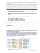
Figure 28 Flow of Authentication of Hosts (In a Fibre Channel environment) Each case in the flow is explained as follows. Case A to Case D in (page 43) corresponds that below. • When performing authentication of host groups ◦ If the user information for the host is registered on the host group, and authentication of the host is enabled (Case A): The host group authenticates the user information sent from the host.
If the host is not configured for authentication by host groups with CHAP, the authentication fails and the host cannot connect to the storage system. ◦ If the user information for the host is registered on the host group, but authentication of the host is disabled (Case B): The host group does not perform authentication of the host. The host will connect to the storage system without authentication, regardless of whether or not the host is configured for authentication by host groups with CHAP.
Figure 29 Example of Authentication of Hosts In (page 45), host group 1 performs authentication of hosts, but host group 2 does not. The user information for Host A is registered on host group 1, and the authentication setting is enabled. Therefore, if authentication of the host is successful, Host A can connect to the storage system (or, the processing goes on to the authentication of the host group).
(page 46) shows the relationship between the combinations of host group settings and the connection results in authentication of hosts. Regardless of whether or not the host is configured for authentication by ports with CHAP, the connection results are as follows, unless otherwise noted.
Figure 30 Flow of Authentication of Fibre Channel Switch Each case in the flow is explained as follows. Case A to Case D in (page 47) corresponds that below. • When performing authentication of Fibre Channel switches by ports: ◦ If the user information for the Fibre Channel switch is registered on the port, and authentication of the Fibre Channel switch is enabled (Case A): Each port authenticates the Fibre Channel switch.
If the Fibre Channel switch of the port is not configured for authentication with CHAP, the authentication fails and the Fibre Channel switch cannot connect to the storage system. ◦ If the user information for the Fibre Channel switch is registered on the port, but authentication of the Fibre Channel switch is disabled (Case B): The ports do not perform authentication of the Fibre Channel switch.
and secret) specified on the port side matches that stored on the host, the host allows the host group to connect. Configuring Fibre Channel Authentication Enabling or Disabling Host Authentication You can specify whether or not to perform authentication of hosts on each host group. Change the user authentication settings of the host groups to enable or disable authentication of hosts. By default, user authentication is disabled. To enable authentication for hosts in a host group: 1.
You can register user information for a host even if the port status is disable however, the registered user information is ignored. 4. 5. . In this case, Right-click any point in the Authentication Information (Host) list. Select Add New User Information from the pop-up menu. The Add New User Information (Host) dialog box ((page 50)) appears. In this dialog box, specify the following user information for the host to which you want to connect. • Group Name Specify the group name of host bus adapter.
Changing Host User Information You can change the registered user name or secret of a host, and change authentication settings between enable and disable after registration. You cannot change the WWN when you change user information. To change user information for a host registered on a host group: 1. Make sure that Remote Web Console is in Modify mode. 2. Start LUN Manager and display the Authentication window ((page 26)). 3.
5. Select Delete User Information from the pop-up menu. Delete Authentication Information dialog box ((page 52)) appears and asks if you want to delete the selected user information for the host. 6. 7. Click the OK button to close the message. Click the Apply button in the Authentication window. A message appears and asks if you want to apply the setting to the storage system. 8. Click the OK button to close the message. The setting is applied to the storage system.
. - + @ _ = : / [ ] , ~ • Re-enter Secret Specify the secret again for confirmation. 5. Click the OK button to close the Specify Authentication Information dialog box. The specified user information for the port appears in blue in the Authentication Information (Target) list of the Authentication window. 6. Click the Apply button in the Authentication window. A message appears and asks if you want to apply the setting to the storage system. 7. Click the OK button to close the message.
Port Authentication Setting Port Information To perform user authentication in Fibre Channel environment, you need to specify information on the Fibre Channel ports of the storage system. To specify information for a Fibre Channel port: 1. Make sure that Remote Web Console is in Modify mode. 2. Start LUN Manager and display the Authentication window ((page 23)). 3. In the Port tree, double-click the Subsystem folder.
3. In the Port tree, double-click the Subsystem folder. If the storage system contains any Fibre Channel adapters, the Fibre folder displays below the Subsystem folder. 4. In the Port tree, double-click the Fibre folder. The information for the port appears in the tree. 5. Right-click any port icon in the Port tree, and select Default Setting(User Name/Secret) from the pop-up menu. The Default Setting(User Name/Secret) dialog box ((page 50)) appears.
3. In the Port tree, double-click the Subsystem folder. If the storage system contains any Fibre Channel adapters, the Fibre folder displays below the Subsystem folder. 4. In the Port tree, double-click the Fibre folder. The information for the Fibre Channel switch appears in the FC Switch Information list. 5. 6. Right-click any point in the FC Switch Information list Select Specify User Information from the pop-up menu. The Specify Authentication Information dialog box ((page 56)) appears.
3. In the Port tree, double-click the Subsystem folder. If the storage system contains any Fibre Channel adapters, the Fibre folder displays below the Subsystem folder. 4. In the Port tree, double-click the Fibre folder. The information for the Fibre Channel switch appears in the FC Switch Information list. 5. Right-click any point in the FC Switch Information list and select Clear User information from the pop-up menu.
Enabling or Disabling Switch Authentication To enable Fibre Channel switches to authenticate hosts, you must enable the user authentication settings of Fibre Channel switches. By default, the Fibre Channel switch authentication is disabled. To enable a Fibre Channel switch to authenticate hosts: 1. Make sure that Remote Web Console is in Modify mode. 2. Start LUN Manager and display the Authentication window ((page 23)). 3. In the Port tree, double-click the Subsystem folder.
NOTE: The change in the dialog box will not affect any port that satisfies one of the following conditions: 8. • The resulting nickname is already used as the nickname of a host bus adapter connected to the port. • The resulting WWN exists in the port. Click the OK button to close the Change WWN & Name dialog box. If a message appears and asks if you want to continue the operation, click the OK button. The changes are indicated in blue in the tree.
Figure 40 Dialog Box that Displays the Host Bus Adapters to be Changed Deleting Host Bus Adapters from Host Groups To delete an HBA from a host group: 1. Start LUN Manager and display the LUN Manager window ((page 13)). 2. In the tree, select and right-click a host bus adapter ( ). A pop-up menu appears. 3. Select Delete WWN from the pop-up menu. A message appears, asking whether you want to delete the host bus adapter (WWN). 4. 5. Click the YES button to close the message.
Changing the Name or Host Mode of a Host Group Use LUN Manager to change the name or host mode of a host group. You cannot perform this operation on host groups for initiator ports. CAUTION: Before you change the host mode of a host group, HP recommends that you first back up the data on the port to which the host group belongs. The operation for setting the host mode is not destructive, but data integrity cannot be guaranteed without a backup. To change the name and/or the host mode of a host group: 1.
NOTE: After you click the Option button, the dialog box expands to display the list of host mode options. The No. column indicates option numbers. Select the check box for the option you want to specify. Deleting Host Groups NOTE: You cannot delete host group 0 (zero). To remove all the WWNs and LU paths from host group 0, you must initialize host group 0 (for details, see (page 62)). To delete a host group: 1. Start LUN Manager and display the LUN Manager window ((page 13)). 2.
Configuring Fibre Channel Ports You can use the Port window ((page 19)) to configure Fibre Channel ports in your storage system. You can also use this window to modify the port configuration when the system is in operation.
Table 5 Available Addresses for Fibre Channel Ports Port Address (AL-PA) Loop ID Port Address (AL-PA) Loop ID Port Address (AL-PA) Loop ID Port Address (AL-PA) Loop ID Port Address (AL-PA) Loop ID EF 0 B4 30 76 60 49 90 10 120 E8 1 B3 31 75 61 47 91 0F 121 E4 2 B2 32 74 62 46 92 08 122 E2 3 B1 33 73 63 45 93 04 123 E1 4 AE 34 72 64 43 94 02 124 E0 5 AD 35 71 65 3C 95 01 125 DC 6 AC 36 6E 66 3A 96 DA 7 AB 37 6D 67 39 97 D9
1. 2. 3. Start LUN Manager and display the Port window ((page 19)). In the Package tree, select the Fibre folder or a channel adapter of a Fibre Channel ((page 19)). • If you select the Fibre folder, the Port list displays a list of Fibre Channel ports in the storage system. • If you select a channel adapter, the Port list displays a list of Fibre Channel ports on the channel adapter. Select a port from the Port list or the Select a Port list.
learn whether FC-AL or point-to-point should be used. Some fabric switches require you to specify point-to-point to get the system running. If no fabric switch is used, you must specify FC-AL. To specify the topology: 1. Start LUN Manager and display the Port window ((page 19)). 2. In the Package tree, select the Fibre folder or a channel adapter of Fibre Channel ((page 19)). 3. • If you select the Fibre folder, the Port list displays a list of Fibre Channel ports in the storage system.
When you apply High Speed mode or Initiator/External MIX mode, each pair of ports in a port block must satisfy the following conditions. • The two ports take the same fabric option (Enable or Disable). • The two ports take FC-AL as the Connection option. • The two ports use different port addresses and no matching addresses. • When you apply High Speed mode, the two ports take the same port attribute (the attribute can be Initiator, RCU target, or Target).
If High Speed mode is applied to the four ports in a port block, only two of the ports can be used for connecting the host. When hosts issue I/Os to ports, the I/Os will be processed by processors on channel adapters. I/Os to each port will be processed by only one processor in Standard mode, but by two processors in High Speed mode. Therefore, ports in High Speed mode can process I/Os faster than ports in Standard mode.
Table 6 Port Serial Numbers and Port Names (4-port Fibre Channel Adapter) (continued) Port serial number Standard mode High Speed mode or Initiator/External MIX mode Port serial number Standard mode High Speed mode or Initiator/External MIX mode 16 CL1-C CL1-C 48 CL1-L CL1-L 17 CL3-C CL3-C [1-C 2nd] 49 CL3-L CL3-L [1-L 2nd] 18 - - 50 - - 19 - - 51 - - 20 CL1-D CL1-D 52 CL1-M CL1-M 21 CL3-D CL3-D [1-D 2nd] 53 CL3-M CL3-M [1-M 2nd] 22 - - 54 - - 23 - - 55 - -
Port serial number Standard mode High Speed mode or Initiator/External MIX mode Port serial number Standard mode High Speed mode or Initiator/External MIX mode 80 CL9-C CL9-C 112 CL9-L CL9-L 81 CLB-C CLB-C [9-C 2nd] 113 CLB-L CLB-L [9-L 2nd] 82 - - 114 - - 83 - - 115 - - 84 CL9-D CL9-D 116 CL9-M CL9-M 85 CLB-D CLB-D [9-D 2nd] 117 CLB-M CLB-M [9-M 2nd] 86 - - 118 - - 87 - - 119 - - 88 CL9-G CL9-G 120 CL9-Q CL9-Q 89 CLB-G CLB-G [9-G 2nd] 121 CL
Port serial number Standard mode High Speed mode or Initiator/External MIX mode Port serial number Standard mode High Speed mode or Initiator/External MIX mode 145 CL4-C CL4-C [2-C 2nd] 177 CL4-L CL4-L [2-L 2nd] 146 - - 178 - - 147 - - 179 - - 148 CL2-D CL2-D 180 CL2-M CL2-M 149 CL4-D CL4-D [2-D 2nd] 181 CL4-M CL4-M [2-M 2nd] 150 - - 182 - - 151 - - 183 - - 152 CL2-G CL2-G 184 CL2-Q CL2-Q 153 CL4-G CL4-G [2-G 2nd] 185 CL4-Q CL4-Q [2-Q 2nd] 154 - -
Port serial number Standard mode High Speed mode or Initiator/External MIX mode Port serial number Standard mode High Speed mode or Initiator/External MIX mode 210 - - 242 - - 211 - - 243 - - 212 CLA-D CLA-D 244 CLA-M CLA-M 213 CLC-D CLC-D [A-D 2nd] 245 CLC-M CLC-M [A-M 2nd] 214 - - 246 - - 215 - - 247 - - 216 CLA-G CLA-G 248 CLA-Q CLA-Q 217 CLC-G CLC-G [A-G 2nd] 249 CLC-Q CLC-Q [A-Q 2nd] 218 - - 250 - - 219 - - 251 - - 220 CLA-H CLA-H 252
Table 7 Port Serial Numbers and Port Names (8-port Fibre Channel Adapter) (continued) Port serial number Standard mode High Speed mode or Initiator/External MIX mode Port serial number Standard mode High Speed mode or Initiator/External MIX mode 18 CL5-C CL5-C 50 CL5-L CL5-L 19 CL7-C CL7-C [5-C 2nd] 51 CL7-L CL7-L [5-L 2nd] 20 CL1-D CL1-D 52 CL1-M CL1-M 21 CL3-D CL3-D [1-D 2nd] 53 CL3-M CL3-M [1-M 2nd] 22 CL5-D CL5-D 54 CL5-M CL5-M 23 CL7-D CL7-D [5-D 2nd] 55 CL7-M CL7
Port serial number Standard mode High Speed mode or Initiator/External MIX mode Port serial number Standard mode High Speed mode or Initiator/External MIX mode 82 CLD-C CLD-C 114 CLD-L CLD-L 83 CLF-C CLF-C [D-C 2nd] 115 CLF-L CLF-L [D-L 2nd] 84 CL9-D CL9-D 116 CL9-M CL9-M 85 CLB-D CLB-D [9-D 2nd] 117 CLB-M CLB-M [9-M 2nd] 86 CLD-D CLD-D 118 CLD-M CLD-M 87 CLF-D CLF-D [D-D 2nd] 119 CLF-M CLF-M [D-M 2nd] 88 CL9-G CL9-G 120 CL9-Q CL9-Q 89 CLB-G CLB-G [9-G 2nd
Port serial number Standard mode High Speed mode or Initiator/External MIX mode Port serial number Standard mode High Speed mode or Initiator/External MIX mode 147 CL8-C CL8-C [6-C 2nd] 179 CL8-L CL8-L [6-L 2nd] 148 CL2-D CL2-D 180 CL2-M CL2-M 149 CL4-D CL4-D [2-D 2nd] 181 CL4-M CL4-M [2-M 2nd] 150 CL6-D CL6-D 182 CL6-M CL6-M 151 CL8-D CL8-D [6-D 2nd] 183 CL8-M CL8-M [6-M 2nd] 152 CL2-G CL2-G 184 CL2-Q CL2-Q 153 CL4-G CL4-G [2-G 2nd] 185 CL4-Q CL4-Q [2-Q 2nd] 15
Port serial number Standard mode High Speed mode or Initiator/External MIX mode Port serial number Standard mode High Speed mode or Initiator/External MIX mode 212 CLA-D CLA-D 244 CLA-M CLA-M 213 CLC-D CLC-D [A-D 2nd] 245 CLC-M CLC-M [A-M 2nd] 214 CLE-D CLE-D 246 CLE-M CLE-M 215 CLG-D CLG-D [E-D 2nd] 247 CLG-M CLG-M [E-M 2nd] 216 CLA-G CLA-G 248 CLA-Q CLA-Q 217 CLC-G CLC-G [A-G 2nd] 249 CLC-Q CLC-Q [A-Q 2nd] 218 CLE-G CLE-G 250 CLE-Q CLE-Q 219 CLG-G CLG-G [E-G
Table 8 Port Serial Numbers and Port Names (HP XP20000 Disk Array) (continued) Port serial number Standard mode 68 CL9-B 69 High Speed mode, Initiator/External MIX mode Port serial number Standard mode High Speed mode, Initiator/External MIX mode CL9-B 196 CLA-B CLA-B CLB-B CLB-B [9-B 2nd] 197 CLC-B CLC-B [A-B 2nd] 70 CLD-B CLD-B 198 CLE-B CLE-B 71 CLF-B CLF-B [D-B 2nd] 199 CLG-B CLG-B [E-B 2nd] 72 CL9-E CL9-E 200 CLA-E CLA-E 73 CLB-E CLB-E [9-E 2nd] 201 CLC-E CLC-E
Viewing a List of Concatenated Parity Groups The storage system supports concatenation of parity groups. If parity groups are concatenated, a logical volume can be dispersed across the concatenated parity groups. Dispersal of logical volumes can provide faster access to data (particularly, faster sequential access to data). NOTE: Only an HP service representative can concatenate parity groups. If you have any questions about concatenation of parity groups, ask your HP service representative.
6. 7. 8. Click OK to close the message. The selected LU path is removed from the table. Click Apply in the LUN Manager window. A message appears asking whether to apply the setting to the storage system. Click OK to close the message. The settings are applied to the storage system and the specified LU paths are deleted. Figure 45 Information about LU Paths to be Deleted NOTE: If you delete numerous paths at one time, the deletion may take time and the dialog box may seem to hang temporarily.
c. d. Right-click the copy destination port. Select Paste from the pop-up menu. If a message appears and asks if you want to continue the operation, click OK. NOTE: You cannot paste paths to initiator ports. To copy one or more (but not all) LU paths defied to a host group, take the following steps: a. Select the host group from the tree. b. From the LU Path list on the right, select one or more LUNs to which volumes are assigned.
Figure 46 Alternate Paths Dialog Box NOTE: The Group ID column indicates group numbers (G-IDs) of the host group. Using LUN Security To protect mission-critical data in your storage system from illegal access, you need to secure the logical volumes in the storage system. Use LUN Manager to secure LUs from illegal access by enabling LUN security on ports. By default, LUN security is disabled on each port. When configuring your system, you must enable LUN security on ports.
7. Click the Apply button in the LUN Manager window. A message appears and asks if you want to apply the setting to the storage system. 8. Click the OK button to close the message. The change in the security settings is applied to that storage system. Disabling LUN Security CAUTION: Do not disable LUN security on ports when host I/O is in progress. To disable LUN security on a port: 1. Start LUN Manager and display the LUN Manager window ((page 13)). 2. In the tree, locate the desired port. 3.
1. 2. 3. Start LUN Manager and display the LUN Manager window ((page 13)). In the upper-right LU Path list or the lower-right LDEV list, select and right-click the desired logical device. • If nothing is displayed in the LU Path list, select a host group • The icons • The icon and in the tree. indicate command devices. indicates no logical device. From the pop-up menu, select Command Device: Disable -> Enable. A message appears, asking if you want to use the logical device as a command device.
5. Click the Apply button in the LUN Manager window. A message appears and asks if you want to apply the setting to the storage system. 6. Click the OK button to close the message. The settings are applied to the storage system. Related topic To remove command device security from a logical device, you must select and right-click the logical device ( ) in the upper-right LU Path list or the lower-right LDEV list and then select Cmd. Dev. Security: Enable -> Disable from the pop-up menu.
6. In the Set UUID window (see (page 85) and (page 85)), enter a UUID in the UUID box. If a UUID is already specified in the UUID box, you can change it. However, if multiple LUNs, or N/As are selected, the UUID box is blank. • For an OpenVMS server host, use a numerical value from 1 to 32,767 (see (page 85)). • For a server host other than OpenVMS, use up to 64 ASCII characters (letters, numerals, and symbols) for a UUID (see (page 85)).
NOTE: When the host mode 05 OpenVMS is used, the disk storage system version cannot be downgraded if a host mode option 33 is set to ON, or a UUID is set. If you want to downgrade the version, make sure the host mode option 33 is set to OFF, clear the setting of UUID, and then perform the downgrade. Though a host mode option 33 is set to OFF and the setting of UUID is cleared, an alarm message may be displayed. In this case, retry the downgrade.
6 Performing LUN Manager Operations Using Configuration File Loader This chapter provides instructions for performing LUN Manager operations using Configuration File Loader. • Page 87 • Page 88 • Page 89 • Page 93 • Page 100 Using Configuration File Loader Use Configuration File Loader to define channel adapter (CHA) settings, port settings, and so on.
Figure 49 Configuration File Loader Operation Flow Chart This chapter provides an overview of LUN Manager spreadsheets that are required for settings using Configuration File Loader. For details on how to import spreadsheets, see the HP XP24000/XP20000 Remote Web Console User Guide. Spreadsheet File Requirements You will need to write the spreadsheet according to specific rules and in a specific format. (page 89) shows an example of a spreadsheet.
Figure 50 Sample Spreadsheet All of the formatting requirements in (page 89) must be satisfied. Table 10 Spreadsheet File Formatting Requirements Item Requirements File type Text file File name Extension must be .spd. Maximum number of letters for the file name is 32 including the extension. The following symbols cannot be used for the file name: \ / : , ; * ? “ < > | and space. File path must be under 255 letters.
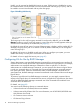
Spreadsheet Declaration The spreadsheet declaration is required, and is written at the beginning of the spreadsheet. Certain parts of the declaration will have already been written in the exported current spreadsheet. If the declaration line is incorrect, an error occurs and the spreadsheet file will be rejected. NOTE: • The spreadsheet declaration line is not case-sensitive.
• The row after the function tag indicates the required setting items (Cha and PcbMode in the example) for the function. The setting items are separated by commas. ◦ Example: [Cha] #Cha, PcbMode • The existing settings for the function are written. The existing settings row, which starts with #$, is recognized as a comment row. CAUTION: ◦ The settings in the rows that start with #$ are not allowed to change.
Configuration definition settings must comply with the following: • The current settings area and the new settings area must be in exactly the same format, with three blank columns in between. • The maximum number of columns for the settings depends on the program product, and is stated in the declaration row. • The number of the available columns for each function tag depends on the number of parameters that can be set for each function and on the version of the spreadsheet.
Comments You can also type comment rows in the spreadsheet by beginning a row with the # character. The comment row can consist of any characters in any language. A row that includes only a linefeed code is also recognized as a comment row.
Table 12 LUN Manager Spreadsheet Format (continued) Function Tag Column [Cha] [Port] [HostGroup] [WWN] [LUN] [LDEV] 5th Connection Option[0:31] Blank Cu Cmd Sec 6th Channel speed Option[32:63] Ldev Blank 7th Blank Option[64:95] Blank Blank 8th Blank 9th Blank 10th Blank 11th Cha Port Port Port Port Ldkc 12th PcbMode Security Switch Group Id Group Id Group Id Cu 13th Blank AL-PA Group Name WWN LunId Ldev 14th Fabric Host Mode Nickname Ldkc Cmd Dev 15th
Table 13 Available Configuration Values for the [CHA] Tag (continued) Column Item Available Values HighSpeed(Block-B): The lower two ports of the CHA are the High Speed mode. • High Speed mode of 32 ports: Standard: Standard mode (all ports) HighSpeed: High Speed mode (all ports) HighSpeed(Block-ABCD): Define four blocks as A, B, C, D, and write only for the High Speed mode in the order of A, B, C, D.
Table 14 Available [Port] Tag Configuration Values (continued) Column Item Available Value 5th, 15th Connection FC-AL or PtoP 6th, 16th Channel Speed Set one of the following: • 8 Gbps settings 2, 4, 8, or Auto • Other settings 1, 2, 4, or Auto Setting the Host Group Use the [HostGroup] tag to add, delete, or change the host group information. The following parameters apply: • You can delete the settings for host group 0 (zero), but the host group itself cannot be deleted.
Table 15 Available Configuration Values for the [HostGroup] Tag (continued) Column Item Available Values 6th, 16th Option[32:63] The default value when the spreadsheet is exported is in eight digits. 7th, 17th Option[64:95] 0s at the head of the number can be omitted when you set the value. (page 97) shows the concept of the host mode option. The host mode option consists of 96 flags, which are from 0 to 95. The host mode option is stored by dividing 32 flags.
Setting the WWN Information Use the [WWN] tag allows to add, delete, or change the WWN information. (page 98) lists the items and values available for the [WWN] tag.
Table 18 Available Configuration Values for the [LUN] Tag (continued) Column Item Available Values BA, BB, BC, BD, BE, BF, BG, BH, BJ, BK, BL, BM, BN, BP, BQ, BR, CA, CB, CC, CD, CE, CF, CG, CH, CJ, CK, CL, CM, CN, CP, CQ, CR, DA, DB, DC, DD, DE, DF, DG, DH, DJ, DK, DL, DM, DN, DP, DQ, DR, EA, EB, EC, ED, EE, EF, EG, EH, EJ, EK, EL, EM, EN, EP, EQ, ER, FA, FB, FC, FD, FE, FF, FG, FH, FJ, FK, FL, FM, FN, FP, FQ, FR, GA, GB, GC, GD, GE, GF, GG, GH, GJ, GK, GL, GM, GN, GP, GQ, GR 2nd, 12th (Index) Group Id
Table 19 Available Configuration Values for the [LDEV] Tag (continued) Column Item Available Value ON or OFF are also available as the set value when you write the spreadsheet. 6th, 7th, Blank 16th, 17th CAUTION: When the configuration definitions is long, the [LDEV] tag might not be output in the exporting spreadsheet. Add the LDEV tag and set the command device.
LDEV:00 - FF LUN: 0000 - 07FF Group ID: 00 - FE Host Mode: 00 - 4F • Level 2 check: The current settings are compared to the imported settings and checked for logical consistency. Note that certain errors can only be detected by the third check. When you import a spreadsheet with no errors detected, the window displays Ready above the error information list, and the Apply button becomes available.
7 Troubleshooting This chapter describes how to troubleshoot LUN Manager problems. • Page 102 • Page 102 Troubleshooting For troubleshooting information on the storage system, see the HP XP24000/XP20000 Disk Array Owner Guide. For a complete list of Remote Web Console error codes, see the HP XP24000/XP20000 Remote Web Console Error Codes. Calling HP Technical Support If you need to call HP technical support, make sure you can provide as much information about the problem as possible.
8 Support and Other Resources Related Documentation • HP XP24000/XP20000 Audit Log User and Reference Guide • Hitachi Cache Manager User Guide • HP XP24000/XP20000 Cache Residency Manager User Guide • HP XP RAID Manager User Guide • HP XP24000/XP20000 for FlashCopy Mirroring Software User Guide • HP XP24000/XP20000 for Compatible Parallel Access Volumes Software User Guide • HP XP24000/XP20000 for Compatible XRC User Guide • HP XP24000/XP20000 Snapshot User Guide • HP XP24000/XP20000 Data R
In the Storage section, click Storage Software and then select a product.
• http://www.hp.com/support/manuals • http://www.hp.com/storage/spock Documentation Feedback HP welcomes your feedback. To make comments and suggestions about product documentation, send a message to storagedocsFeedback@hp.com. All submissions become the property of HP.
Glossary C CHAP Challenge-Handshake authentication protocol. CU Control unit. CV, CVS Custom-sized volume, also called customized volume. D DASD Direct access storage device. DKCMAIN Disk controller main. F FD Floppy disk. H High Speed mode A mode that can be applied to a channel adapter board. If you apply High Speed mode to a channel adapter board, port performance will be improved but only one of the ports on the channel adapter board will be usable.
U UUID User-definable LUN ID or logical volume ID. W WWN Worldwide Name, which is a unique identifier for a host bus adapter of a particular open-system host, consisting of a 64-bit physical address (the IEEE 48-bit format with 12-bit extension and 4-bit prefix).
Index A AIX finding WWN, 33 C conventions storage capacity values, 104 D document related documentation, 103 documentation HP website, 103 providing feedback, 105 F finding WWN AIX, 33 HP-UX, 31 Sequent, 33 SGI Irix, 33 Sun Solaris, 32 Windows NT/2000, 30 H help obtaining, 104 HP technical support, 104 HP-UX finding WWN, 31 L LightPulse Utility/NT window illustration, 31 LUN security overview, 6 O overview LUN security, 6 P port names and serial numbers (4–port) table, 69 port names and serial number