HP XP24000/XP20000 Virtual LVI/LUN (VLL) and Volume Shredder User Guide Abstract This user guide provides instructions for using the Virtual LVI/LUN and Volume Shredder options on the HP storage system.
© Copyright 2007, 2011 Hewlett-Packard Development Company, L.P. Confidential computer software. Valid license from HP required for possession, use or copying. Consistent with FAR 12.211 and 12.212, Commercial Computer Software, Computer Software Documentation, and Technical Data for Commercial Items are licensed to the U.S. Government under vendor's standard commercial license. The information contained herein is subject to change without notice.
Contents 1 Overview of Virtual LVI/LUN and Volume Shredder.........................................5 Virtual LVI/LUN (VLL).................................................................................................................5 Volume Shredder......................................................................................................................5 2 About Virtual LVI/LUN and Volume Shredder.................................................6 Overview of Virtual LVI/LUN..................
Select Progress Dialog Box.......................................................................................................58 System Disk Options Dialog Box...............................................................................................59 5 Performing Virtual LVI/LUN and Volume Shredder Operations........................61 Virtual LVI/LUN Operations......................................................................................................61 Launching Virtual LVI/LUN.........
1 Overview of Virtual LVI/LUN and Volume Shredder This chapter provides a brief description of Virtual LVI/LUN and Volume Shredder. • “Virtual LVI/LUN (VLL)” (page 5) • “Volume Shredder” (page 5) Unless otherwise specified, the term storage system in this guide refers to the following disk arrays: • HP XP24000 Disk Array • HP XP20000 Disk Array The GUI illustrations in this guide were created using a Windows computer with the Internet Explorer browser.
2 About Virtual LVI/LUN and Volume Shredder This chapter provides an in-depth overview of Virtual LVI/LUN and Volume Shredder. • “Overview of Virtual LVI/LUN” (page 6) • “Overview of LDEV Formatting” (page 18) • “Overview of Quick Formatting” (page 18) • “Overview of Configuring External Mainframe Volumes” (page 19) • “Overview of Volume Shredder” (page 19) Virtual LUN is a function for open systems. To use this function, you need the software called Open Volume Management.
The VLL operations include: Volume to Space, Install CV, Volume Initialize, and Make Volume. • The Volume to Space function formats one or more of the LDEVs on a selected Virtual Device (VDEV) into free space. This free space can be used to install one or more variable-sized volumes (CVs) using the Install CV function or remain as free space for future usage. • The Volume Initialize function removes all CVs under a Virtual LVI/LUN volume, and reformats the Virtual LVI/LUN volume as a VDEV.
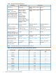
Table 1 Virtual LVI/LUN Specifications Parameter Track format Mainframe system 3380, 3390 Open system OPEN-3, OPEN-8, OPEN-9, OPEN-V OPEN-E Emulation type 3380-3, 3380-3A, OPEN-3, OPEN-8, OPEN-9, OPEN-V 3380-3B, 3380-3C, OPEN-E NOTE: The emulation 3380-F*, 3380-K*, types followed by an asterisk 3380-KA*, 3380-KB*, (*) can only be used with 3380-KC* Fujitsu mainframe systems.
Table 2 CV Capacity by Emulation Types (for Mainframe System) (continued) Emulation type Minimum CV capacity (Cyl) Maximum CV capacity (Cyl) Number of control cylinders (Cyl) 3390-3A 1 3,339 6 3390-3B 1 3,339 6 3390-3C 1 3,339 6 3390-3R 1 3,339 6 3390-9 1 10,017 25 3390-9A 1 10,017 25 3390-9B 1 10,017 25 3390-9C 1 10,017 25 3390-L 1 32,760 23 3390-LA 1 32,760 23 3390-LB 1 32,760 23 3390-LC 1 32,760 23 3390-M 1 65,520 53 3390-MA 1 65,520 53 3390-MB
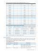
Table 4 SSID Requirements (continued) Controller emulation type SSID requirement LVI/LUN Support 3390-3, 3390-3A, 3390-3B, 3390-3C, 3390-3R, 3390-9, 3390-9A, 3390-9B, 3390-9C, 3390-L, 3390-LA, 3390-LB, 3390-LC, 3390-M, 3390-MA, 3390-MB, 3390-MC, OPEN-3, OPEN-8, OPEN-9, OPEN-E, and OPEN-V volumes Specifications for VLL/LUSE Devices WARNING! LDEVs larger than 2 TB cannot be remotely copied to an HP XP1024/XP128 Disk Array or an HP XP512/XP48 Disk Array.
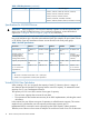
size, the free space generated when multiple CVs are created may be smaller than the free space generated when one CV is created. If the data protection level is set to the enhanced mode on the SATA drive, you must calculate the entire capacity of CVs in existence, and the entire capacity of CVs in the enhanced mode of the data protection level. For details about the size calculation, see “Size Calculation of Volumes (Data Protection Level is Set to Enhanced Mode on SATA Drive)” (page 14).
NOTE: • ◦ The value enclosed in two upward arrows ( ) must be rounded up to the nearest whole number. ◦ The user area capacity is expressed in kilobytes ◦ The boundary value is expressed in kilobytes. The boundary value depends on the volume emulation types and RAID levels (see “Boundary Value for Each RAID Level” (page 16)).
NOTE: ◦ The value enclosed in two upward arrows ( ) must be rounded up to the nearest whole number. ◦ The user-specified CV capacity is expressed in blocks. ◦ The boundary value is expressed in kilobytes. The boundary value depends on the volume emulation types and RAID levels (see “Boundary Value for Each RAID Level” (page 16)).
To calculate the entire capacity of a CV, use the following formula. The resulting entire capacity is expressed in blocks. To convert the resulting entire capacity into megabytes, divide the capacity by 2,048. (user-specified-CV-capacity + management-area-capacity × 2) ÷ (boundary-value × 2) × (boundary-value × 2) NOTE: ◦ The value enclosed in two upward arrows ( ) must be rounded up to the nearest whole number. ◦ The user-specified CV capacity is expressed in blocks.
To convert the resulting entire capacity into megabytes, use the following formula. Calculated-entire-capacity-of-a-CV(slots) in the following formula means the entire capacity of a CV if the data protection level is set to the enhanced mode on the SATA drive. calculated-entire-capacity-of-a-CV(slots) ÷ 1024 x capacity-of-a-slot • If the unit for CV capacity is block: To calculate the entire capacity of a CV, use the following formula. The resulting entire capacity is expressed in slots.
Table 7 Management Area Capacity of an Open-Systems Volume (continued) Emulation Type Management Area Capacity OPEN-E NOTE: 13,680 The management area capacity of an open-systems volume is expressed in kilobytes.
Table 11 Calculated Management Area Capacities Emulation Type RAID1 (2D+2D) RAID5 (3D+1P) RAID5 (7D+1P) RAID6 (6D+2P) 3390-xx 445,440 2,004,480 10,913,280 8,017,920 OPEN-V 122,880 552,960 3,010,560 2,211,840 NOTE: • xx is a variable indicating one or more numbers or letters. • Calculated management area capacities are expressed in slots. • A SATA drive supports the following emulation types: 3390-xx for a mainframe system. OPEN-V for an open system.
Figure 4 Virtual LVI/LUN Volume Configuration Overview of LDEV Formatting The LDEV Format feature allows you to format volumes (including external volumes). To format volumes, you must ensure that the volumes are in blocked status. For detailed information, see “Formatting the LDEVs” (page 70).
• Journal volumes • Volumes for a system disk • Quorum disks Overview of Configuring External Mainframe Volumes To use external volumes with the storage system, usually you must use HP XP External Storage Software to perform external volume mapping, and then use the Format command of Virtual LVI to format the volumes (see “Formatting the LDEVs” (page 70)). However, when you format external mainframe volumes in this way, the formatting operation may take some time.
Therefore, HP recommends that you overwrite a volume at least three times using dummy data. The default setting of Volume Shredder defines three times of overwriting using dummy data. If you change the setting, you can overwrite the volume up to eight times. For details on the setting of Volume Shredder, see “Defining the Shredding Settings” (page 81).
3 Preparing for Virtual LVI/LUN and Volume Shredder Operations This chapter describes the environment that you need to prepare in order to operate VLL and Volume Shredder.
4. 5. 6. 7. Right-click the target volume and select Blockade. A message appears asking if you want to change the volume status. Click OK to close the message. Information about the target volume is shown in blue bold italics. Click Apply. A message appears asking if you want to apply the settings. Click OK to close the message. The status of the volume changes to Blocked. NOTE: 22 • If you select Restore and click Apply, you can change the status of the volume from Blocked to Normal again.
4 Using the Virtual LVI/LUN and Volume Shredder GUI This chapter describes the Virtual LVI/LUN (VLL) and Volume Shredder GUI.
Figure 6 Customized Volume Window 24 Using the Virtual LVI/LUN and Volume Shredder GUI
Tree of Parity Groups and VDEVs • The tree of parity groups and VDEVs (on the left side of the Customized Volume window) shows the hierarchical structure of the storage system. For example, a disk group number (Box1), parity group number (1-1), RAID level (RAID1(2D+2D)), and VDEV number (1-1-(1)) are shown. ◦ If you open the Internal folder, the tree shows parity groups in the local storage system (that is, the storage system you are currently logged in to).
Table 14 LDEV Table Details (continued) Item Description When you manipulate mainframe volumes, you can only select Cyl. No. Volume number. LDKC:CU:LDEV A combination of a logical disk controller (LDKC) number, a control unit (CU) number, and a logical device (LDEV) number. Free indicates free space.
Table 14 LDEV Table Details (continued) Item Description Attribute The attribute of the volume: • Pool (pool-id): The volume is a pool volume (pool-VOL). The pool ID is enclosed by parentheses. • JNL-VOL: The volume is a journal volume. • Volume Security: The volume is a Volume Security volume. • Remote Command Device: The volume is a remote command device. • System Disk: The volume is used for a system disk. • Reserved Volume: The volume is reserved for XP Auto LUN.
Quick Format Execution Display The Customized Volume window shows the number of the parity groups and LDEVs on which quick formatting is in process. The display includes the following: • Status of the parity groups and LDEVs appear with the icons shown in Table 15 (page 28). Table 15 Quick Format Parity Groups and LDEV Status Icons Icon Status Parity group. The number of the parity groups undergoing quick formatting is displayed on the right side of this icon. Normal LDEV.
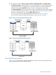
Install CV Dialog Box (1) Use the Install CV dialog boxes to define and install one or more Virtual LVI/LUN volumes under an existing volume. You can specify the emulation type and the capacity of the VLL volume that you want to create. Figure 7 (page 29) shows the first Install CV dialog box. Figure 7 Install CV Dialog Box (1) Item Description Parity Group VDEV number of the selected free space. The VDEV number indicates the parity group where the VDEV belongs.
Item Description Capacity Unit Select the unit in which you want to specify the capacity of the VLL. • MB: Megabytes. This unit is used for specifying the capacity of open-system volumes. • Cyl: Cylinders. This unit is used for specifying the capacity of mainframe volumes and OPEN-V volumes. • Block: Blocks. This unit is used for specifying the capacity of external volumes. For details regarding external volumes, see the HP XP24000/XP20000 External Storage Software User Guide.
Item Description Next Opens the Install CV dialog box (2). Cancel Cancels the selected settings and returns to the Customized Volume window. Install CV Dialog Box (2) The Install CV dialog box (2) shows a table of VLL volumes to be created. Use this dialog box to specify the LDKC numbers, CU numbers, and LDEV numbers of the VLL volumes. Figure 8 Install CV Dialog Box (2) Item Description Parity Group Number of the VDEV to which the VLL volume belongs.
Item Description the 3390-3R emulation type are displayed in the VLL volume setting-information table. This check box is available only when 3390-3R was selected from the Emulation list on the Install CV dialog box (1). If the 3390-3R check box is available, you must set the LDEV number to all VLL volumes that are shown. Select LDEV No. Select the LDKC, CU, and LDEV numbers for the VLL volumes you intend to create. Select LDKC No. Select an LDKC number from this list. The default is 00.
Item Description Next Opens one of the following dialog boxes: • If the boundary area of the selected LDEV number does not have an SSID, the Install CV (Set SSID) dialog box opens. • If the boundary area of the selected LDEV number has an SSID, the Install CV confirmation dialog box opens. Cancel Cancels the settings for the LDEV, and returns to the Customized Volume window. Clear Removes an LDKC:CU:LDEV number that is already assigned.
Figure 9 Set SSID (Install CV) Dialog Box Item Description Set SSID The Set SSID tree is a hierarchical structure of LDKC numbers (for example, LDKC00), CU numbers (for example, CU 00), SSID boundary areas (for example, 00-3F), and SSID (for example, 0004). A boundary area is a group of LDEV numbers to which an SSID is assigned. For example, if a boundary area is 00-FF, an SSID must be assigned to a group of LDEV numbers 00-FF.
Item Description No SSID is assigned to this boundary area. SSID table Use this table to set the SSID boundary area. • LDKC: LDKC for the CU number that contains an LDEV boundary with no SSID. • CU: CU number that contains an LDEV boundary with no SSID. • LDEV Boundary: Boundary area of the LDEV number with no SSID. • SSID: Specified SSID. The default is blank. Input SSID Select or enter the desired SSID. You can enter the SSID only when you logged in as a storage administrator.
Figure 10 Install CV Dialog Box (4) Item Description Parity Group Number of the VDEV to which the VLL volume belongs. The VDEV number indicates the parity group where the VDEV belongs. For example, if the VDEV number is 1-1-(1), the VDEV belongs to a parity group numbered 1-1. A VDEV number that starts with E (for example, E1-1-(1)) indicates that the VDEV belongs to a parity group that consists of one or more external LUs. System Disk Setting table System disk settings on the VLL volume. • No.
Item Description Release Releases the system disk settings from the selected VLL volume. Back Returns to the previous dialog box (that is, Install CV dialog box (2) or Set SSID (Install CV) dialog box). Next Opens the Install CV confirmation dialog box. Cancel Cancels the settings in this dialog box, and returns to the Customized Volume window. Install CV Confirmation Dialog Box Use the Install CV Confirmation dialog box to confirm the settings for the VLL volumes to be created.
Item Description consists of one or more XP Thin Provisioning virtual volumes (V-VOLs). Emulation Emulation type of the VLL volume to be created. Capacity Capacity of the VLL volume displayed in the unit selected from the Capacity Unit list in the Install CV dialog box (1). LDKC:CU:LDEV The LDKC number, the CU number, and the LDEV number of the VLL volume to be created. Option Shows System Disk if the VLL volume is configured as a system disk. Back Returns to the previous dialog box.
Item Description consists of one or more XP Snapshot virtual volumes (V-VOLs). • A VDEV number that starts with X (for example, X1-1-(1)) indicates that the VDEV belongs to a parity group that consists of one or more XP Thin Provisioning virtual volumes (V-VOLs). How to create volume table Information about the VLL volume. • No.: Setting number of the VLL volume in the table. • Emulation: Emulation type of the VLL volume (OPEN-V).
Item Description (minimum - maximum) is shown under the Capacity field (for example, 46 - 6720 MB, 50 - 7168 Cyl, or 315 8513 blocks). When Capacity Unit is MB or Cyl, there might be a difference of up to several hundred kilobytes between the entered CV capacity and the resulting CV capacity. Set remaining space as volume Select to create a VLL volume using the remaining space in the VDEV. This option is available only when the emulation type is OPEN-V.
Item Description example, if the VDEV number is 1-1-(1), the VDEV belongs to a parity group numbered 1-1. • A VDEV number that starts with E (for example, E1-1-(1)) indicates that the VDEV belongs to a parity group that consists of one or more external LUs. • A VDEV number that starts with V (for example, V1-1-(1)) indicates that the VDEV belongs to a parity group that consists of one or more XP Snapshot virtual volumes (V-VOLs).
Item Description blue indicates available LDEV numbers. You can select an LDEV number from the white LDEV numbers in the table. When you set the LDEV number, that LDEV number becomes available and changes to blue. LDEV numbers that are not selectable may already be in use or already assigned to another emulation group (grouped by 32 LDEV numbers). See “Emulation Groups” (page 33).
Figure 14 Set SSID (Make Volume) Dialog Box Item Description Set SSID tree A hierarchical structure of LDKC numbers (for example, LDKC00), CU numbers (for example, CU 00), SSID boundary areas (for example, 00-3F), and SSID (for example, 0004). A boundary area is a group of LDEV numbers to which an SSID is assigned. For example, if a boundary area is 00-FF, an SSID must be assigned to a group of LDEV numbers 00-FF.
Item Description No SSID is assigned to this boundary area. SSID table Use this table to set the SSID boundary area. • LDKC: LDKC for the CU number that contains an LDEV boundary with no SSID. • CU: CU number that contains an LDEV boundary with no SSID. • LDEV Boundary: Boundary area of the LDEV number with no SSID. • SSID: Specified SSID. The default is blank. Input SSID list Select or enter the desired SSID. You can enter the SSID only when logged in as a storage administrator.
Figure 15 Make Volume Dialog Box (4) Item Description Parity Group Number of the VDEV to which the VLL volume belongs. The VDEV number indicates the parity group where the VDEV belongs. For example, if the VDEV number is 1-1-(1), the VDEV belongs to a parity group numbered 1-1. A VDEV number starting with E (for example, E1-1-(1)) indicates that the VDEV belongs to a parity group that consists of one or more external LUs. System Disk Setting Shows system disk settings on the VLL volume. • No.
Item Description Back Returns to the previous dialog box (that is, Make Volume dialog box (2) or Set SSID (Make Volume) dialog box). Next Opens the Make Volume confirmation dialog box. Cancel Cancels the settings in this dialog box, and returns to the Customized Volume window. Make Volume Confirmation Dialog Box Use the Make Volume confirmation dialog box to confirm the settings of the VLL volumes to be created. The VLL volume-setting information table shows a list of VLL volumes to be created.
Item Description LDKC:CU:LDEV The LDKC number, the CU number, and the LDEV number of the VLL volume to be created. Option Shows System Disk if the VLL volume is configured as a system disk. Back Returns to the previous dialog box. OK Registers the Make Volume settings, and returns to the Customized Volume window. Cancel Cancels the Make Volume settings, and returns to the Customized Volume window.
Item Description • Capacity: Capacity of the VLL volume to be initialized, in either megabytes (MB) for open-system volumes or cylinders (Cyl) for mainframe volumes. • LDKC:CU:LDEV: LDKC number, CU number, and LDEV number for the VLL volume to be initialized. The default is blank. 3390-3R When this check box is selected, VLL volumes of the 3390-3R emulation type appear in the Normal volume-setting information table on the left side of this dialog box.
Item Description Next Opens one of the following dialog boxes: • If the boundary area of the selected LDEV number does not have an SSID, opens the Volume Initialize dialog box (2) for setting an SSID. • If the boundary area of the selected LDEV number has an SSID, opens the Volume Initialize (Set SSID) dialog box. Cancel Cancels the settings for the LDEV, and returns to the Customized Volume window. Clear Removes an LDKC:CU:LDEV number that is already assigned.
Item Description boundary areas (for example, 00-3F), and SSID (for example, 0004). A boundary area is a group of LDEV numbers to which an SSID is assigned. For example, if a boundary area is 00-FF, an SSID must be assigned to a group of LDEV numbers 00-FF. The number of boundary areas is 1 or 4 per one CU, depending on the configuration at shipment time. An SSID appears to the right of a boundary area and is enclosed by parentheses.
Volume Initialize Confirmation Dialog Box Use the Volume Initialize confirmation dialog box to confirm the settings of the VLL volumes to be initialized. The VLL volume-setting information table shows a list of VLL volumes to be initialized. Figure 19 Volume Initialize Confirmation Dialog Box (for Confirming Volume Initialize Settings) Item Description VDEV VDEV number for the VLL volume to be initialized.
Item Description OK Registers the Volume Initialize settings, and returns to the Customized Volume window. Cancel Cancels the Volume Initialize settings, and returns to the Customized Volume window. RAID Concatenation Dialog Box In the storage system, data can be written to an LDEV that extends over concatenated parity groups; concatenation of parity groups enables faster access to data. Use the RAID Concatenation dialog box to see a list of the concatenated parity groups on your storage system.
Figure 21 Format All Dialog Box Item Description Action Select the action to perform. • Format: Volumes will be formatted. • Write To Control Blocks: Control blocks in external mainframe volumes will be overwritten. Parity Group Type Select the type of parity group. • Internal: The operation will be performed on internal volumes. • External: The operation will be performed on external volumes. If Action is Write To Control Blocks, Parity Group Type is always External.
Item Description is disconnected, the external volume must be omitted from the operation target. Cancel Cancels the settings in the Format All dialog box, and closes this dialog box. Shredding Param. Dialog Box Use this dialog box to define the settings of the shredding operation. To open the Shredding Param. dialog box, click Shredding Param. in the Customized Volume window. Figure 22 Shredding Param.
Item Description settings, see “Defining the Shredding Settings” (page 81). Write Data Select the contents of the dummy data. • Define — You can enter numbers or characters in the text box, and the data you enter will be used as the dummy data. You can enter only hexadecimal numbers in this text box. Therefore, you can use numbers from 0 to 9 and letters from A to F. You can enter up to 4 digits. • Random — Volume Shredder will select 4-digit hexadecimal numbers at random for the dummy data.
The names of the binary files indicates the LDKC, CU, and LDEV numbers of the shredded volumes, and the number of times dummy data has been written to the volumes. For example, if a binary file is named 00–01-11-03.bin, the LDKC number is 00, the CU number is 01, and the LDEV number is 11. The filename also indicates that dummy data has been written to that volume three times. A binary file contains the first 512 bytes of data of a shredded volume (LDEV).
Table 18 Ending Status of a Shredding Operation (continued) Ending Status Displayed in the Dialog Box Meaning Shredding operation canceled. The shredding operation was canceled. Shredding operation Failed. The shredding operation ended abnormally. Shredding data transfer error The result of the shredding operation could not be output to a file. Shredding data verify error An error was detected while verifying the file containing the result of the shredding operation. No-data assigned.
Figure 24 Shredding Data Output Dialog Box Item Description non-object Volume The result of shredding the volumes in this list will NOT be saved in files. Each row represents one volume. Each volume shows the LDKC number, the CU number, and the LDEV number, delimited by a colon (:). object Volume The result of shredding the volumes in this list will be saved in files. Each row represents one volume. Each volume shows the LDKC number, the CU number, and the LDEV number, delimited by a colon (:).
Figure 25 Select Progress Dialog Box 1 Figure 26 Select Progress Dialog Box 2 Item Description Select Progress Select one operation and click OK to view progress information about the selected operation. • Format: Indicates formatting is in progress. • Shredding: Indicates shredding is in progress. • Preparing Quick Format: Indicates preparation for Quick Format is in progress. OK Closes the dialog box, and shows the progress about the selected operation.
Item Description system operation when you turn on or off the power supply of the storage system. 60 Audit Log buffer Enable is selected while you are using this function. The Audit Log Administrator can define this function to be available or not. To switch this function to Enable or to Disable, use the Audit Log Setting window. For detail about this window, see the HP XP24000/XP20000 Remote Web Console User Guide and the HP XP24000/XP20000 Audit Log User and Reference Guide.
5 Performing Virtual LVI/LUN and Volume Shredder Operations This section describes procedures for performing VLL operations and Volume Shredder operations. • “Virtual LVI/LUN Operations” (page 61) • “Volume Shredder Operations (For Volumes Using Hard Disk)” (page 80) Virtual LVI/LUN Operations You must have write permission for VLL. For details on assigning user access, see the HP XP24000/XP20000 Remote Web Console User Guide.
Converting Logical Volumes to Space WARNING! The Volume to Space function is a destructive operation. The data on the logical volumes being converted is lost when the operation is complete. The user is responsible for backing up the data as needed before performing this operation. The Volume to Space function allows you to convert one or more logical volumes (LDEVs) to space, which deletes the selected LDEVs from that VDEV.
Creating VLL Volumes (Install CV Function) The Install CV function allows you to define and install one or more Virtual LVI/LUN volumes. To define and install one or more Virtual LVI/LUN volumes (CVs) in spaces created with the Volume to Space function, perform Install CV function. Also, to define and install one or more Virtual LVI/LUN volumes (CVs) in free spaces created as a result of creating volumes in VDEVs, perform Install CV function.
d. e. 6. Click Set to display the setting in the How to create volume table. To remove VLL volume settings displayed in the How to create volume table, do the following: • To remove a setting, select the VLL volume, and click Delete. When a confirmation message appears, click OK. • To remove all settings, click Clear. When a confirmation message appears, click OK. To create other VLL volumes, repeat steps a through d. After setting all VLL volumes, go to step 7.
17. After setting all of the SSIDs, select Next. A dialog box appears. 18. Make system disk settings, and then click Next. The Install CV confirmation dialog box appears. 19. Verify that the information displayed in the Install CV confirmation dialog box is correct, and then click OK. The new settings appear in blue bold italics in the LDEV Information table in the Customized Volume window. The setting changes are not yet implemented in the storage system.
• The CV must not be a pool volume (pool-VOL). • The CV must not be a journal volume. • The CV must not be a remote command device. • The CV must not be a volume used by Volume Security. • The CV must not be a quorum system disk. To convert a CV (custom-sized volume) back into an initialized FV (fixed volume): 1. Make sure that Remote Web Console is in Modify mode. For detailed information about Modify mode, see the HP XP24000/XP20000 Remote Web Console User Guide. 2.
12. To apply the changes to the storage system, click Apply (or Cancel to cancel them). While an LDEV is being formatted, a progress window opens. The percentage of completion displayed might be 0% or 99%. This completion percentage could remain visible while the format operation is in progress. If desired, you can make settings on the Make Volume function (see “Re-creating the CVs After Initializing the VDEV (Make Volume Operation)” (page 67)) before clicking Apply.
The following lists the restrictions on CVs for the Make Volume function. If the VDEV contains a CV that violates any of the restrictions, the Make Volume function is disabled. You must eliminate invalid CVs before executing the Make Volume function. • The CV must not be path-defined (including TrueCopy for Mainframe, XP Continuous Access, ShadowImage for Mainframe, XP Business Copy, and XP Continuous Access Journal pair volumes). • The CV must not be reserved for XP Auto LUN.
d. e. 6. Click Set to display the setting in the How to create volume table. To remove VLL volume settings displayed in the How to create volume table, do the following: • To remove a setting, select the VLL volume, and click Delete. When a confirmation message appears, click OK. • To remove all settings, click Clear. When a confirmation message appears, click OK. To set other VLL volumes, repeat steps a through d. After setting all VLL volumes, go to step 7.
19. Make system disk settings, and then click Next. The Make Volume confirmation dialog box appears. 20. Verify that the information displayed in the Make Volume confirmation dialog box is correct, and then click OK. 21. The created VLL volumes appear in blue bold italics in the LDEV Information table on the Customized Volume window. The setting changes are not yet implemented in the storage system.
Blocking Volumes To block a volume: 1. Make sure that Remote Web Console is in Modify mode. For detailed information about Modify mode, see the HP XP24000/XP20000 Remote Web Console User Guide. 2. 3. 4. 5. In the Customized Volume window (“Customized Volume Window” (page 24)), confirm that the current status of your desired volume (external mainframe volume) is displayed as Normal under the Status column of the table. While highlighting your selected volume, right-click and select Blockade.
Figure 28 Message That Appears During Volume Formatting If you click Close to close the message (Figure 28 (page 72)), the progress percentage will not be shown, though the formatting will not be canceled. To re-display the progress percentage, click Progress in the Customized Volume window. To confirm whether the formatting operation has successfully finished after clicking Close, check whether the Status column of the table in the Customized Volume window shows Normal.
a. Check the list to see whether Format appears to the right of the disk groups or parity groups that will be formatted. If Format is not displayed, select the disk groups or the parity groups, and then click Set. The right column will display Format. b. Check the list to see if nothing appears to the right of the disk groups or parity groups that will not be formatted. If anything appears, select the disk groups or parity groups, and then click Release. The right column will become empty. 8.
Table 20 Quick Format Specifications (continued) Items Description The Customized Volume window shows the number of parity groups undergoing Quick Format. If all volumes in one or more parity groups undergoing Quick Format are blocked, the displayed number of parity groups undergoing Quick Format decreases by the number of blocked parity groups. However, the number of parity groups that have not undergone and can undergo Quick Format does not increase.
Table 22 Estimated Required Time for Quick Formatting (continued) Capacity of a Drive (GB) Required Time (hours) 750 17.5 1000 23.5 • Table 22 (page 74) indicates the required time when you execute quick formatting on all the areas in a parity group. When you execute quick formatting on some volumes in a parity group, the required time may be less than the time indicated in Table 22 (page 74).
The required system disk capacity is as follows: • Capacity for Quick Format management information: 46 MB, which means 66 cylinders if the track format is 3380; or NF80, which means 55 cylinders if the track format is 3390. • Capacity for the audit log buffering area: 130 MB, which means 185 cylinders if the track format is 3380; or NF80, which means 154 cylinders if the track format is 3390.
• It has been about an hour and a half since the disk system firmware has been updated. • It has been about an hour and a half since the storage system has been restarted while a Quick Format operation was being performed and data in shared memory was being deleted (volatilized). • It has been about an hour and a half since the Quick Format operation was completed for the first time • The system disk is being used for the Audit Log Buffer function.
5. 6. 7. 8. Click Apply in the Customized Volume window, and then click OK on the confirmation dialog box. VLL starts preparing for quick format and shows a message (Figure 29 (page 78)). When the progress reaches 100%, a notification dialog box will appear to notify you that preparing for quick formatting has been completed. Click OK on the notification dialog box.
• Volume Initialize • Make Volume If an external volume to be operated is disconnected, the external volume must be omitted from the operation target. Overwriting Control Blocks in Specific External Volumes To overwrite the control blocks of a specific external volume: 1. See “Making External Mainframe Volumes Usable” (page 78), and then take steps 1 to 2 in that section. 2. Make sure that Remote Web Console is in Modify mode.
1. 2. See “Making External Mainframe Volumes Usable” (page 78), and then take steps 1 and 2 in that section. Make sure that Remote Web Console is in Modify mode. For detailed information about Modify mode, see the HP XP24000/XP20000 Remote Web Console User Guide. 3. 4. 5. 6. In the Customized Volume window (“Customized Volume Window” (page 24)), click Format All. The Format All dialog box appears. In Action, select Write To Control Blocks. Make sure that Parity Group Type is External.
Defining the Shredding Settings To execute a shredding operation without using the default settings, use the Shredding Param. dialog box to define your shredding settings, which will be used to delete the data from the volumes. To define the shredding settings: 1. Make sure that Remote Web Console is in Modify mode. For detailed information about Modify mode, see the HP XP24000/XP20000 Remote Web Console User Guide. 2. 3. Click Shredding Param.
NOTE: To delete a row from the Format List, select the row, and click Delete. You cannot delete the row that is defined as Last Data. Deleting the Data in the Target Volume To execute a shredding operation to delete data from volumes: 1. Make sure that Remote Web Console is in Modify mode. For detailed information about Modify mode, see the HP XP24000/XP20000 Remote Web Console User Guide. 2.
11. Select the folder where you want to download the file. 12. Click OK. If you have chosen to download the file, the file is downloaded to the specified folder. If you have not chosen to download the file, the confirmation dialog box for the completion of the shredding operation is closed. When the shredding operation is finished, the status of the volume will be automatically changed to Normal.
Time required to overwrite data in the target volume with dummy data The time required to overwrite data in the target volume with dummy data (the worst case) depends on the model of the data-deleting target volume and the time to overwrite with dummy data. • Given this model of the data deleting target volume: RAID configuration: 7D+1P • The time required for overwriting data in the target volume with dummy data is the following.
Calculating the Number of Shredding Operations Necessary to Overwrite Data in Target Volume with Dummy Data to Delete When a flash disk is used, space is newly allocated in response to a write request and the target volume to delete data is converted to space. For this, data deleting by overwriting data using the data exceeding the capacity of target volume is required. Procedures to calculate the number of shredding operations necessary to overwrite data in the target volume with dummy data are as follows.
6 Troubleshooting This chapter explains how to troubleshoot problems that you might experience while using Virtual LVI/LUN or Volume Shredder. • “Troubleshooting” (page 86) • “Calling HP Technical Support” (page 86) Troubleshooting • For troubleshooting information on the storage system, see the HP XP24000/XP20000 Disk Array Owner Guide. • For troubleshooting information on the Remote Web Console software, see the HP XP24000/XP20000 Remote Web Console User Guide.
7 Support and Other Resources Related Documentation • HP XP24000/XP20000 Cache Residency Manager User Guide • HP XP24000/XP20000 Snapshot User Guide • HP XP24000/XP20000 Thin Provisioning Software User Guide • HP XP24000/XP20000 LUN Manager User Guide • HP XP24000/XP20000 Remote Web Console Error Codes • HP XP24000/XP20000 Remote Web Console User Guide • HP XP24000/XP20000 External Storage Software User Guide • HP XP24000/XP20000 Disk Array Owner Guide • HP XP24000/XP20000 Disk Encryption U
• Product serial numbers • Error messages • Operating system type and revision level • Detailed questions Subscription Service HP recommends that you register your product at the Subscriber’s Choice for Business website: http://www.hp.com/go/e-updates After registering, you will receive email notification of product enhancements, new driver versions, firmware updates, and other product resources. HP Websites For additional information, see the following HP websites: • http://www.hp.
Glossary C cache extents areas used for Cache Residency Manager Cache Residency Manager dynamic cache residency CU Control unit. CV customized volume D DKC Disk controller. F FV fixed-size volume J JNL journal L LD, LDEV Logical device. An LDEV is created when a RAID group is carved into pieces according to the selected host emulation mode (that is, OPEN-3, OPEN-8, OPEN-9). The number of resulting LDEVs depends on the selected emulation mode. The term LDEV is also known as term volume.
S SATA Serial Advanced Technology Attachment. SIM Service information message. SLPR Storage logical partition. SSID storage system ID SSID Subsystem identifier; storage system identifier. SVP service processor SVP Service processor. A computer built into a disk array. The SVP, used only by an HP service representative, provides a direct interface to the disk array. T TB Terabyte. Equivalent to 1,000 Gb for data storage and statistics, or 1,024 Gb for memory.
Index B boundary limitation, 17 C Concatenation List, 61 conventions storage capacity values, 87 converting logical volumes to space, 62 normal volumes to free space, 62 Customized Volume window, 23 changes, 65 Format All dialog box, 52 Install CV confirmation dialog box, 37 Install CV dialog box (2), 31 Install CV dialog box (4), 35 Install CV dialog boxes (1), 29 Make Volume confirmation dialog box, 46 Make Volume dialog box (2), 40 Make Volume dialog box (4), 44 parity group status icons, 25 Set SSID (I
conventions, 87 storage systems supported models, 5 Subscriber's Choice, HP, 88 system requirements Virtual LVI/LUN (VLL), 21 Volume Shredder, 21 T technical support, 88 calling, 86 HP, 87 troubleshooting, 86 U unique SSID, 9 V VDEV, 6 VDEV status icons, 25 VDEV volume configuration, 18 Virtual LVI/LUN (VLL) creating VLL volumes, 63 deleting VLL volumes, 65 functions, 6 Install CV function, 7 launching, 61 LUSE specifications, 10 Make Volume function, 7 operations, 61 overview, 6 preparing to use, 21 siz