H3C LSW1FC4P0 Interface Card for S5820X-28C Ethernet Switches QuickTools User Guide Firmware Version 9.0.
H3C LSW1FC4P0 Interface Card for S5820X-28C Ethernet Switches QuickTools User Guide The information in this document is subject to change without notice. Every effort has been made in the preparation of this document to ensure accuracy of the contents, but all statements, information, and recommendations in this document do not constitute the warranty of any kind, express or implied.
Table of Contents Preface Intended Audience . . . . . . . . . . . . . . . . . . . . . . . . . . . . . . . . . . . . . . . . . . . . Related Materials . . . . . . . . . . . . . . . . . . . . . . . . . . . . . . . . . . . . . . . . . . . . . JDOM License . . . . . . . . . . . . . . . . . . . . . . . . . . . . . . . . . . . . . . . . . . . . . . . 1 Using QuickTools Workstation Requirements . . . . . . . . . . . . . . . . . . . . . . . . . . . . . . . . . . . . . . Opening QuickTools . . . . . . . . . . . .
H3C LSW1FC4P0 Interface Card for S5820X-28C Ethernet Switches QuickTools User Guide Switch Properties. . . . . . . . . . . . . . . . . . . . . . . . . . . . . . . . . . . . . . . . . Syslog . . . . . . . . . . . . . . . . . . . . . . . . . . . . . . . . . . . . . . . . . . . . . Symbolic Name . . . . . . . . . . . . . . . . . . . . . . . . . . . . . . . . . . . . . H3C LSW1FC4P0 Interface Card Administrative States . . . . . . ENODE MAC Address Configuration . . . . . . . . . . . . . . . . . . . . .
H3C LSW1FC4P0 Interface Card for S5820X-28C Ethernet Switches QuickTools User Guide Port States . . . . . . . . . . . . . . . . . . . . . . . . . . . . . . . . . . . . . . . . . . . . . . External Port Operational States . . . . . . . . . . . . . . . . . . . . . . . . Internal Port Operational States . . . . . . . . . . . . . . . . . . . . . . . . . Port Administrative States. . . . . . . . . . . . . . . . . . . . . . . . . . . . . . Port Types . . . . . . . . . . . . . . . . . . . . . . . . . . . . . . .
H3C LSW1FC4P0 Interface Card for S5820X-28C Ethernet Switches QuickTools User Guide Figures Figure Page 1-1 Login to Switch Dialog . . . . . . . . . . . . . . . . . . . . . . . . . . . . . . . . . . . . . . . . . . . . . . . 2 1-2 Password Change Required Dialog . . . . . . . . . . . . . . . . . . . . . . . . . . . . . . . . . . . . . 3 1-3 QuickTools Interface. . . . . . . . . . . . . . . . . . . . . . . . . . . . . . . . . . . . . . . . . . . . . . . . . 3 1-4 Preferences Dialog – QuickTools . . . . . .
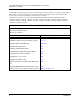
H3C LSW1FC4P0 Interface Card for S5820X-28C Ethernet Switches QuickTools User Guide Tables Table 1-1 1-2 2-3 2-4 2-5 2-6 2-7 2-8 2-9 2-10 2-11 2-12 2-13 2-14 3-15 3-16 3-17 3-18 3-19 3-20 3-21 3-22 3-23 Workstation Requirements . . . . . . . . . . . . . . . . . . . . . . . . . . . . . . . . . . . . . . . . . . . . Menu Bar Options . . . . . . . . . . . . . . . . . . . . . . . . . . . . . . . . . . . . . . . . . . . . . . . . . . Switch Data Window Entries . . . . . . . . . . . . . . . . . . . . . . . . .
H3C LSW1FC4P0 Interface Card for S5820X-28C Ethernet Switches QuickTools User Guide viii 59273-00 C
Preface This guide describes the QuickTools™ web applet for the H3C LSW1FC4P0 Interface Card (firmware version 9.0.7). QuickTools is the primary focus of this guide which is organized as follows: Section 1 describes how to use QuickTools, its menus, and its displays. Section 2 describes H3C LSW1FC4P0 Interface Card management tasks. Section 3 describes port and device management tasks. A glossary of terms and an index are also provided.
JDOM License This product includes software developed by the JDOM Project (http://www.jdom.org/). Copyright (C) 2000-2002 Brett McLaughlin & Jason Hunter. All rights reserved. Redistribution and use in source and binary forms, with or without modification, are permitted provided that the following conditions are met: 1. Redistributions of source code must retain the above copyright notice, this list of conditions, and the following disclaimer. 2.
1 Using QuickTools This section describes how to use QuickTools and its menus. The following topics are covered: Workstation Requirements Opening QuickTools QuickTools User Interfaces Setting QuickTools Preferences Using Online Help Viewing Software Version Exiting QuickTools Workstation Requirements The requirements for fabric management workstations running QuickTools are listed in Table 1-1. Table 1-1.
Using QuickTools Opening QuickTools Table 1-1. Workstation Requirements Internet Browser Microsoft® Internet Explorer® 6.0 and later (to view online help Netscape® Navigator® 6.0 and later Firefox® 1.5 and later Safari® 1.0 on Windows OS Java 2 Standard Edition Runtime Environment 1.4.2 to support the web applet Opening QuickTools After the H3C LSW1FC4P0 Interface Card is operational, open QuickTools by entering the H3C LSW1FC4P0 Interface Card IP address in an Internet browser.
Using QuickTools QuickTools User Interfaces Figure 1-2. Password Change Required Dialog QuickTools User Interfaces The H3C LSW1FC4P0 Interface Card faceplate is displayed in the graphic window and shows the front of a single H3C LSW1FC4P0 Interface Card and its ports. The QuickTools interface (Figure 1-3) consists of a menu bar, graphic window, data windows (some with buttons), and data window tabs. Menu Bar Switch Name and Status Graphic Window Data Window Data Window Tabs Figure 1-3.
Using QuickTools QuickTools User Interfaces Graphic Window The graphic window shows the H3C LSW1FC4P0 Interface Card faceplate display (Figure 1-3). The card name has a small icon next to it that uses color to indicate operational status: A green icon indicates normal operation. A yellow icon indicates that the H3C LSW1FC4P0 Interface Card is operational, but may require attention to maintain maximum performance.
Using QuickTools QuickTools User Interfaces Menu Bar QuickTools menu bar options are listed in Table 1-2. Table 1-2.
Using QuickTools QuickTools User Interfaces Table 1-2. Menu Bar Options (Continued) Menu View Options Refresh View Port Types View Port States View Port Speeds View Port Media Hide TH Map Help Help Topics About Popup Menus Popup menus are displayed when you right-click the H3C LSW1FC4P0 Interface Card faceplate image in the graphic window.
Using QuickTools Setting QuickTools Preferences Selected ports in the faceplate display are outlined in blue. You can select ports the following ways. To select a port, click the port. To select all ports, right-click on the faceplate image and select Select All Ports from the popup menu. To select a range of consecutive ports, click a port, press the Shift key and click another port. The web applet selects both end ports and all ports in between the end ports.
Using QuickTools Setting QuickTools Preferences Choose the default port view when opening the faceplate display. You can set the faceplate to reflect the current port type (default), port speed, port operational state, or port transceiver media. Regardless of the default port view you choose, you can change the port view in the faceplate display by opening the View menu and selecting a different port view option.
Using QuickTools Using Online Help Using Online Help The browser-based online help system can be accessed from QuickTools several ways. Online help is also context-sensitive, that is, the online help opens to the topic that describes the dialog you have open.
Using QuickTools Exiting QuickTools 10 59273-00 C
2 Managing H3C LSW1FC4P0 Interface Card This section describes the following tasks that manage an H3C LSW1FC4P0 Interface Card in a fabric.
Managing H3C LSW1FC4P0 Interface Card Displaying Interface Card Information Security Consistency Checklist To display configuration information for the H3C LSW1FC4P0 Interface Card, open the Switch menu, and select Security Consistency Checklist. The Security Consistency Checklist dialog displays current configuration information as shown in Figure 2-5. Figure 2-5.
Managing H3C LSW1FC4P0 Interface Card Displaying Interface Card Information Information in the Switch data window is grouped and accessed by the Summary, Status, Network, User Login, Firmware, Services, and Advanced buttons. Click a button to display the grouped information in the data window on the right. Figure 2-7 describes the Switch data window buttons. Figure 2-7. Switch Data Window Buttons The Switch data window entries are listed in Table 2-3. Table 2-3.
Managing H3C LSW1FC4P0 Interface Card Displaying Interface Card Information Table 2-3.
Managing H3C LSW1FC4P0 Interface Card Displaying Interface Card Information Table 2-3. Switch Data Window Entries (Continued) Entry Description Temperature Failure Port Shutdown Non-configurable (always enabled for this H3C LSW1FC4P0 Interface Card). All ports are downed when the H3C LSW1FC4P0 Interface Card temperature exceeds the Failure Temperature.
Managing H3C LSW1FC4P0 Interface Card Displaying Interface Card Information Table 2-3. Switch Data Window Entries (Continued) Entry Description SNMP v3 Security Enabled SNMP v3 Security enabled or disabled Broadcast Support N/A - does not apply to this switch NTP Client Enabled Enabled or disabled. Allows for switches to synchronize their time to a centralized server. NTP Server Address The IP address of the centralized NTP server. Ethernet connection to NTP server is required.
Managing H3C LSW1FC4P0 Interface Card Displaying Interface Card Information Table 2-3. Switch Data Window Entries (Continued) Entry 59273-00 C Description FDMI Enabled N/A - does not apply to this switch FDMI HBA Entry Limit N/A - does not apply to this switch Embedded GUI Enabled QuickTools web applet status. Enables or disables the web applet on the H3C LSW1FC4P0 Interface Card.
Managing H3C LSW1FC4P0 Interface Card Managing User Accounts Managing User Accounts Only the Admin account can manage user accounts with the User Account Administration dialogs. However, any user can modify their own password. To open the User Account Administration dialogs, open the Switch menu and select User Accounts.
Managing H3C LSW1FC4P0 Interface Card Managing User Accounts Creating User Accounts To create a user account on an H3C LSW1FC4P0 Interface Card, open the Switch menu and select User Accounts to open the User Account Administration dialog (Figure 2-8). An H3C LSW1FC4P0 Interface Card can have a maximum of 15 user accounts. Figure 2-8. User Account Administration Dialog – Add Account 59273-00 C 1. To open the User Account Administration dialogs, open the Switch menu and select User Accounts. 2.
Managing H3C LSW1FC4P0 Interface Card Managing User Accounts Removing a User Account To remove a user account on an H3C LSW1FC4P0 Interface Card, open the Switch menu and select User Accounts. Click the Remove Account tab in the User Account Administration dialog to present the display (Figure 2-9). Select the account (login) name from the list of accounts at the top of the dialog and click the Remove Account button. Figure 2-9.
Managing H3C LSW1FC4P0 Interface Card Managing User Accounts Changing a User Account Password To change the password for an account on an H3C LSW1FC4P0 Interface Card, open the Switch menu and select User Accounts. Click the Change Password tab in the User Account Administration dialog to present the display (Figure 2-10).
Managing H3C LSW1FC4P0 Interface Card Managing User Accounts Modifying a User Account To modify a user account on an H3C LSW1FC4P0 Interface Card, open the Switch menu and select User Accounts. Click the Modify Account tab in the User Account Administration dialog to present the display (Figure 2-11). Select the account (login) name from the list of accounts at the top of the dialog. Select the Admin Authority Enabled option to grant admin authority to the account name.
Managing H3C LSW1FC4P0 Interface Card Configuring Port Threshold Alarms Configuring Port Threshold Alarms You can configure the interface card to generate alarms for selected events. Configuring an alarm involves choosing an event type, rising and falling triggers, a sample window, and finally enabling or disabling the alarm. To configure port threshold alarms, do the following: 1. In the faceplate display, open the Switch menu and select Port Threshold Alarm Configuration.
Managing H3C LSW1FC4P0 Interface Card Paging an H3C LSW1FC4P0 Interface Card 5. Enter a value for the rising trigger. A rising trigger alarm is generated when the event count per interval exceeds the rising trigger. The interface card will not generate another rising trigger alarm for that event until the count descends below the falling trigger and rises again above the rising trigger. Consider the example in Figure 2-13. 6. Enter a value for the falling trigger.
Managing H3C LSW1FC4P0 Interface Card Setting the Date/Time and Enabling NTP Client Setting the Date/Time and Enabling NTP Client The Date/Time dialog allows you to manually set the date, time, and time zone on a switch, or to enable NTP (Network Time Protocol) Client to synchronize the date and time on the switch with an NTP server. Enabling the NTP client requires an Ethernet connection to an NTP server, but ensures the consistency of date and time stamps in alarms and log entries.
Managing H3C LSW1FC4P0 Interface Card Resetting an H3C LSW1FC4P0 Interface Card Resetting an H3C LSW1FC4P0 Interface Card Resetting an H3C LSW1FC4P0 Interface Card reboots the H3C LSW1FC4P0 Interface Card using configuration parameters in memory. Depending on the reset type, an H3C LSW1FC4P0 Interface Card reset may or may not include a Power On Self Test or it may or may not disrupt traffic. Table 2-5 describes the types of H3C LSW1FC4P0 Interface Card resets.
Managing H3C LSW1FC4P0 Interface Card Configuring an H3C LSW1FC4P0 Interface Card Table 2-5. H3C LSW1FC4P0 Interface Card Resets Type Description Hot Reset Resets an H3C LSW1FC4P0 Interface Card without a Power On Self Test. This reset activates the pending firmware, but does not disrupt H3C LSW1FC4P0 Interface Card traffic. If errors are detected on a port during a hot reset, the port is reset automatically. Reset Resets an H3C LSW1FC4P0 Interface Card without a Power On Self Test.
Managing H3C LSW1FC4P0 Interface Card Configuring an H3C LSW1FC4P0 Interface Card Use the Switch Properties dialog to change the following H3C LSW1FC4P0 Interface Card configuration parameters: Syslog Symbolic Name H3C LSW1FC4P0 Interface Card Administrative States ENODE MAC Address Configuration Figure 2-14. Switch Properties Dialog Syslog The Syslog (Remote Logging) feature enables saving of the log information to a remote host that supports the syslog protocol.
Managing H3C LSW1FC4P0 Interface Card Configuring an H3C LSW1FC4P0 Interface Card H3C LSW1FC4P0 Interface Card Administrative States The H3C LSW1FC4P0 Interface Card administrative state determines the operational state of the H3C LSW1FC4P0 Interface Card. The H3C LSW1FC4P0 Interface Card administrative state exists in two forms: the configured administrative state and the current administrative state.
Managing H3C LSW1FC4P0 Interface Card Configuring an H3C LSW1FC4P0 Interface Card Managing System Services The System Services dialog (Figure 2-15) provides a central location for you to enable or disable any of the external user services such as Simple Network Management Protocol (SNMP), embedded web applet, command line interface, Network Time Protocol (NTP), and Common Information Model (CIM). To display the System Services dialog, open the Switch menu and select Services. Figure 2-15.
Managing H3C LSW1FC4P0 Interface Card Configuring an H3C LSW1FC4P0 Interface Card 59273-00 C SNMP (Simple Network Management Protocol) — allows management of the H3C LSW1FC4P0 Interface Card through third-party applications that use SNMP. NTP (Network Time Protocol) — allows the H3C LSW1FC4P0 Interface Card to obtain its time and date settings from an NTP server.
Managing H3C LSW1FC4P0 Interface Card Configuring an H3C LSW1FC4P0 Interface Card Configuring FCoE The FCoE (Fibre Channel over Ethernet) feature enables you create a bridge between the Fibre Channel fabric and an Ethernet VLAN (Virtual Local Area Network). This bridge allows devices using an Ethernet connection to log in to a Fibre Channel fabric through a FCF (Fibre Channel over Ethernet Forwarder).
Managing H3C LSW1FC4P0 Interface Card Configuring an H3C LSW1FC4P0 Interface Card Configuring VLAN Manager The VLAN Manager dialog enables you to add, remove, or reset VLAN port assignments. To open the VLAN Manager dialog (Figure 2-17), open the Switch menu, select FCoE, and select VLAN Manager. In the VLANs area, the list of existing VLANs on this switch is displayed along with the maximum number of VLANs allowed on the switch. The VLAN Assignments area shows the VLAN each Ethernet port is in.
Managing H3C LSW1FC4P0 Interface Card Configuring an H3C LSW1FC4P0 Interface Card Configuring FCF Configuration Manager The FCF is a Fibre Channel Switching Element with one or more “lossless” Ethernet MACs, each coupled with an FCoE Controller. An FCF forwards FCoE frames addressed to it based on the D_ID of the encapsulated FC frames. The FCF Configuration Manager dialog (Figure 2-19) enables you to add a new FCF configuration, or remove/ edit an existing FCF configuration.
Managing H3C LSW1FC4P0 Interface Card Configuring an H3C LSW1FC4P0 Interface Card Creating a new FCF The FCF Editor dialog (Figure 2-20) enables you to add/modify the following: FCMap, Enforce Keep Alive Timer, the Keep Alive Timer Range, the FIP Priority, VLANs, and MAC Addresses. Click the OK button and if the FCF passes validation, it will be added to the configured list in the FCF Configuration Manager dialog.
Managing H3C LSW1FC4P0 Interface Card Configuring an H3C LSW1FC4P0 Interface Card Table 2-7 defines the parameters in the FCF Editor dialog. Table 2-7. FCF Editor dialog parameters Parameter Description FCmap Name A user-defined name consisting of 6 hexadecimal characters Enforce Keep Alive Timer Determines if the Keep Alive Timer is enforced. The Keep Alive Timer Range can still be modified, even if this box is not modified.
Managing H3C LSW1FC4P0 Interface Card Configuring an H3C LSW1FC4P0 Interface Card Configuring Network Properties Use the Network Properties DNS (Domain Name Service) dialog (Figure 2-21) to enable the DNS Client on the switch and the DNS server to map domain names to IP addresses. To open the Network Properties dialog, select a switch in the topology display or open the faceplate display, open the Switch menu, select Network, and select Network Properties.
Managing H3C LSW1FC4P0 Interface Card Configuring an H3C LSW1FC4P0 Interface Card Table 2-8 describes the Network Properties DNS values. Table 2-8. Network Properties—DNS Configuration Parameter Description DNS Client Domain Name Service client Local Hostname The name of local host Server Discovery Choose one of the following methods by which to assign the IP address: Static — uses the IP configuration parameters entered in the Network Properties dialog.
Managing H3C LSW1FC4P0 Interface Card Configuring an H3C LSW1FC4P0 Interface Card Configuring SNMP Configuring the Simple Network Management Protocol includes: SNMP Properties Configuration SNMP Trap Configuration SNMP v3 Manager and User Configuration SNMP Properties Use the SNMP Properties dialog (Figure 2-22) to change SNMP configuration parameters. After making changes, click the OK button to put the new values into effect.
Managing H3C LSW1FC4P0 Interface Card Configuring an H3C LSW1FC4P0 Interface Card SNMP Configuration The SNMP configuration defines how authentication traps are managed. Table 2-9 describes the SNMP configuration parameters. The illegal characters for the user-defined fields are the pound sign (#), semi-colon (;), and comma (,). Table 2-9. SNMP Configuration Parameters Parameter 40 Description SNMP Enabled Enables or disables SNMP communication with other H3C LSW1FC4P0 Interface Cards in the fabric.
Managing H3C LSW1FC4P0 Interface Card Configuring an H3C LSW1FC4P0 Interface Card SNMP Trap Configuration The SNMP trap configuration defines how traps are set. Choose from the tabs Trap1–Trap 5 to configure each trap. Table 2-10 describes the SNMP configuration parameters. Table 2-10. SNMP Trap Configuration Parameters Parameter a 59273-00 C Description Trap Version Specifies the SNMP version (1 or 2) with which to format traps. Trap 1 Enabled Enables or disables the trap.
Managing H3C LSW1FC4P0 Interface Card Configuring an H3C LSW1FC4P0 Interface Card SNMPv3 Security Simple Network Management Protocol Version 3 (SNMPv3) is an interoperable standards-based protocol for network management. SNMPv3 provides secure access to devices by a combination of authenticating and encrypting packets over the network. SNMPv3 security is an additional layer of security offered with the 9.0.7 firmware.
Managing H3C LSW1FC4P0 Interface Card Configuring an H3C LSW1FC4P0 Interface Card Figure 2-24. SNMP v3 User Editor Dialog Table 2-11 describes the SNMP v3 User Editor dialog parameters. After configuring the user, click the OK button to save the settings and close the dialog. Table 2-11. SNMP v3 User Editor Dialog Parameter 59273-00 C Description User Name Name for this SNMPv3 user. Group Read Only permits user to view only SNMPv3 user settings.
Managing H3C LSW1FC4P0 Interface Card Archiving an H3C LSW1FC4P0 Interface Card Archiving an H3C LSW1FC4P0 Interface Card You can create an .XML archive file containing the configuration parameters. Basically any data received by QuickTools is archived. This archive file can be used to restore the configuration on the same H3C LSW1FC4P0 Interface Card or on a replacement H3C LSW1FC4P0 Interface Card.
Managing H3C LSW1FC4P0 Interface Card Restoring an H3C LSW1FC4P0 Interface Card CAUTION! The H3C LSW1FC4P0 Interface Card being restored should be physically disconnected from the fabric. Restoring an H3C LSW1FC4P0 Interface Card in a fabric can severely disrupt the fabric. After the restore process is complete, the H3C LSW1FC4P0 Interface Card can be reconnected to the fabric. To restore an H3C LSW1FC4P0 Interface Card, do the following: 1.
Managing H3C LSW1FC4P0 Interface Card Restoring the Factory Default Configuration 4. 5. To restore all configuration settings, click the Full Restore tab, then click the Restore button. To restore selected configuration settings, click the Selective Restore tab and select one or more of the following options, then click the Restore button: Network Properties—restores all settings presented in the Network properties dialog except the IP address. Refer to ”SNMP Properties” on page 2-39.
Managing H3C LSW1FC4P0 Interface Card Restoring the Factory Default Configuration Table 2-12. Factory Default Configuration Settings Setting 59273-00 C Value Symbolic Name H3C LSW1FC4P0 Interface Card Administrative State Online I/O Stream Guard Disabled Device Scan Enabled True SNMP Enabled True SNMP Proxy True IP Address 10.90.90.xx Where xx changes based on slot Subnet Mask Address 255.255.255.0 Gateway Address 0.0.0.
Managing H3C LSW1FC4P0 Interface Card Testing an Interface Card Testing an Interface Card The Switch Diagnostics dialog (Figure 2-26) allows you to test and verify operational status of switches. To open the Switch Diagnostic dialogs, open the Switch menu, select Switch Diagnostics > Offline Switch Diagnostics.
Managing H3C LSW1FC4P0 Interface Card Using the Event Browser 3. Enter a frame size in the Frame Size field. 4. Enable or disable the Terminate Test Upon Error option. 5. Select a Loop Count option. The Loop Forever option runs the test until you click the Stop Test button. The Loop Count option runs the test the number of times you specify in the Loop Count field. 6. Select the default test pattern or enter a user-defined (hexadecimal) test pattern. 7.
Managing H3C LSW1FC4P0 Interface Card Using the Event Browser To display the Event Browser, open the File menu and select Show Event Browser. If the Show Event Browser selection is grayed-out, you must first enable the Events Browser preference. Refer to ”Setting QuickTools Preferences” on page 1-7. Column Sorting Buttons Severity Column Figure 2-27. Events Browser Severity is indicated in the severity column using icons as described in Table 2-13. Table 2-13.
Managing H3C LSW1FC4P0 Interface Card Using the Event Browser NOTE: Events (Alarms, Critical, Warning, and Informative) generated by the web applet are not saved on the switch. They are permanently discarded when you close a QuickTools session, but you can save these events to a file on the workstation before you close QuickTools and read it later with a text editor or browser.
Managing H3C LSW1FC4P0 Interface Card Using the Event Browser Figure 2-28. Filter Events Dialog Sorting the Event Browser Sorting the Event Browser enables you to display the events in alphanumeric order based on the event severity, timestamp, source, type, or description. Initially, the Event Browser is sorted in ascending order by timestamp. To sort the Event Browser, click the Severity, Timestamp, Source, Type, or Description column buttons.
Managing H3C LSW1FC4P0 Interface Card Downloading a Support File Downloading a Support File The Download Support File menu option assembles all log files and H3C LSW1FC4P0 Interface Card memory data into a core dump file (dump_support.tgz). This file can be sent to technical support personnel for troubleshooting H3C LSW1FC4P0 Interface Card problems. The menu option is not accessible (displayed) for an H3C LSW1FC4P0 Interface Card that doesn't support the download support file function.
Managing H3C LSW1FC4P0 Interface Card Installing Firmware After an NDCLA operation is complete, management connections must be re-initiated: QuickTools sessions will re-connect automatically Telnet sessions must be restarted manually.
Managing H3C LSW1FC4P0 Interface Card Using Call Home To install firmware, do the following: 1. In the faceplate display, open the Switch menu and select Load Firmware. 2. In the Load Firmware dialog, click the Browse button next to the Firmware Image Folder field to browse for and select the folder containing firmware file to be loaded. 3. Select the firmware file from the Firmware Image Folder. 4. Click the Start button to begin the firmware load process.
Managing H3C LSW1FC4P0 Interface Card Using Call Home Table 2-14 lists the fields in the Call Home Setup dialog. Table 2-14. Call Home Setup Dialog Fields Setting Primary SMTP: (active) Value The "(active)" indicates the Primary SMTP (Simple Mail Transfer Protocol) is the SMTP server that CallHome is going to try to use when transmitting Email messages. CallHome operates as an SMTP client, or more correctly, and SMTP sending agent.
Managing H3C LSW1FC4P0 Interface Card Using Call Home Table 2-14. Call Home Setup Dialog Fields (Continued) Setting From Email Address: Value The Email address that will be provided to the SMTP server to indicate the sender of the Email being transmitted. In Emails sent by Call Home, this address will appear in the message heading as the "From: " address. This value is required to send Emails.
Managing H3C LSW1FC4P0 Interface Card Using Call Home Using the Call Home Profile Manager Use the Call Home Profile Manager dialog (Figure 2-31) to manage all profiles on a switch. You can add new profiles, remove profiles, edit profiles, and make copies of existing profiles. To display the Call Home Profile Manager dialog, open the Switch menu, select Call Home, and select Profile Manager. The Profiles list shows all profiles on the switch.
Managing H3C LSW1FC4P0 Interface Card Using Call Home Using the Call Home Profile Editor Use the Call Home Profile Editor dialog when creating a new profile, and editing/copying an existing profile. The Call Home Profile Editor dialog is displayed after clicking the Add, Edit, or Copy buttons on the Call Home Profile Manager dialog.
Managing H3C LSW1FC4P0 Interface Card Using Call Home Applying All Profiles on a Switch to Other Switches You can apply all profiles on a switch to one or more switches in a fabric. The Call Home Profile Multiple Switch Apply dialog (Figure 2-33) is displayed after selecting the Apply Changes to Multiple Switches in Fabric option on the Call Home Profile Manager dialog. The Available Switches list shows all switches in the fabric.
Managing H3C LSW1FC4P0 Interface Card Using Call Home Using the Call Home Message Queue Use the Call Home Message Queue dialog (Figure 2-34) to access the logged call home statistics. Click the Update Stats button to refresh with the most recent switch Call Home information. Click the Clear Queue button to clear the current statistics. Figure 2-34.
Managing H3C LSW1FC4P0 Interface Card Using Call Home 62 59273-00 C
3 Managing Ports The data windows provide port information and port statistics for selected ports. This section describes the following tasks that manage ports and devices: Port Statistics Data Windows Port Information Data Window Viewing and Configuring Ports Resetting a Port Testing Ports Mapping Ports Port Statistics Data Windows Port statistics data windows display statistics about port performance.
Managing Ports Port Statistics Data Windows FC Port Statistics Data Window The FC Port Stats data window (Figure 3-36) displays performance statistics for the Fibre Channel (External) ports. Figure 3-36. FC Port Statistics Data Window Table 3-15 describes the FC Port Statistics data window entries. Table 3-15. FC Port Statistics Data Window Entries Entry 64 Description Start Time The beginning of the period over which the statistics apply. The start time for the Absolute view is not applicable.
Managing Ports Port Statistics Data Windows Table 3-15. FC Port Statistics Data Window Entries (Continued) Entry 59273-00 C Description Bad Frames Number of frames that were truncated due to a loss of sync or the frame didn't end with an EOF. BB_CreditRecoveryFr ameFailure Number of times more frames were lost during a credit recovery period than the recovery process could resolve. This causes a Link Reset to recover the credits.
Managing Ports Port Statistics Data Windows Table 3-15. FC Port Statistics Data Window Entries (Continued) Entry 66 Description Invalid Destination Address Number of address identifier (S_ID, D_ID) errors. AL_PA equals non-zero AL_PA found on F_Port. Link Failures Number of optical link failures detected by this port. A link failure is a loss of synchronization or by loss of signal while not in the offline state.
Managing Ports Port Statistics Data Windows Table 3-15. FC Port Statistics Data Window Entries (Continued) Entry 59273-00 C Description Total LIPs Received Number of loop initialization primitive frames received. Total LIPs Transmitted Number of loop initialization primitive frames transmitted. Tx Offline Sequences Number of offline primitives transmitted by the port. Total Rx Frames Total number of frames received by the port. Total Rx Words Total number of words received by the port.
Managing Ports Port Statistics Data Windows Ethernet Port Statistics Data Window The Ethernet Port Stats data window (Figure 3-37) displays performance statistics for the Ethernet (Internal) ports. Figure 3-37. Ethernet Port Statistics Data Window Table 3-16 describes the Ethernet Port Statistics data window entries. Table 3-16. Ethernet Port Statistics Data Window Entries Entry 68 Description Start Time The beginning of the period over which the statistics apply.
Managing Ports Port Statistics Data Windows Table 3-16. Ethernet Port Statistics Data Window Entries (Continued) Entry 59273-00 C Description Class 3 Toss Number of class 3 frames that were discarded by this port. A frame can be discarded because of detection of a missing frame (based on SEQ_CNT), detection of an E_D_TOV timeout, receiving a reject frame, or receiving a frame on an offline port. Decode Errors Number of invalid transmission words detected during decoding.
Managing Ports Port Statistics Data Windows Table 3-16.
Managing Ports Port Information Data Window Port Information Data Window The Port Information data window (Figure 3-38) displays detailed port information for the selected ports. To open the Port Information data window, click the Port Info data window tab. Figure 3-38. Port Information Data Window Information in the Port Information data window is grouped and viewed by the Summary, Advanced, and Media buttons. Click a button to display the corresponding information in the data window on the right.
Managing Ports Port Information Data Window Table 3-17. Port Information Data Window Entries Entry Description Summary Group 72 Port Address N/A - does not apply to this switch Administrative Port Type The administrative port type (TF, TH, and PT). This value is persistent; it will be maintained during an H3C LSW1FC4P0 Interface Card reset. During port auto-configuration, it will be used to determine which operational port states are allowed.
Managing Ports Port Information Data Window Table 3-17. Port Information Data Window Entries (Continued) Entry Description Operational Port Speed The speed actually being used by the port. Port Speed Supported The TF port speeds supported are:2Gbps, 4Gbps, and 8Gbps. The speed supported for TH and PT ports is 10Gbps.
Managing Ports Viewing and Configuring Ports Table 3-17. Port Information Data Window Entries (Continued) Entry Description VLAN The VLAN for the selected port MAC Address N/A - does not apply to this switch Fabric WWN N/A - does not apply to this switch Login Limit Exceeded Indicates if the maximum number of logins is reached Media Group Media Type The transceiver fibre type, such as single mode, multi-mode, copper. Media Speed The maximum transceiver speed Media The transceiver type.
Managing Ports Viewing and Configuring Ports Port Transceiver Media Status Device Scan DCBX PFC Priority The port settings or characteristics are configured using the Port Properties dialog (Figure 3-40). To open the Port Properties dialog, select one or more ports, open the Port menu and select Port Properties. Figure 3-40.
Managing Ports Viewing and Configuring Ports Port States The port operational state refers to actual port state and not the administrative state you may have assigned. Refer to ”External Port Operational States” on page 3-76 and ”Internal Port Operational States” on page 3-77 for port operational state information. The port administrative state refers to the user-requested state. Port administrative states have two forms: the configured administrative state and the current administrative state.
Managing Ports Viewing and Configuring Ports Internal Port Operational States The operational states on the internal ports in the faceplate display are described in Table 3-19. Table 3-19. Internal Port Operational States State Description Logged In — DCBX enabled. The Port SyncStatus has been acquired, and Port Link State is "Active".
Managing Ports Viewing and Configuring Ports Port Administrative States The port administrative state determines the operational state of a port. The port administrative state has two forms: the configured administrative state and the current administrative state. Configured administrative state — the state that is saved in the H3C LSW1FC4P0 Interface Card configuration and is preserved across H3C LSW1FC4P0 Interface Card resets. QuickTools always makes changes to the configured administrative state.
Managing Ports Viewing and Configuring Ports Port Types The 4 external ports connect to fabrics and can be configured as Transparent Fabric (TF) or Pass-thru (PT) ports. The 4 internal ports connect to servers and can be configured as Transparent Host (TH) or Pass-thru (PT) ports. See ”Mapping Ports” on page 3-83 for more information. To display port type status, open the View menu, and select View Port Types. Table 3-21 lists the possible port types and their meanings.
Managing Ports Viewing and Configuring Ports Port Speeds The external ports can support 1Gbps, 2Gbps, 4Gbps, or 8Gbps. Internal ports are 10Gbps and can not be changed. Auto-detect is not an option on internal ports. To display the speed of each port, open the View menu and select View Port Speeds. Table 3-22 lists the possible port speeds. To change the port transmission speed, do the following: 1. Select one or more ports in the faceplate display. 2.
Managing Ports Resetting a Port . Table 3-23. Port Transceiver Media View Media Icon Description Optical SFP, online (green/black), logged-in, active, and ready to send data.
Managing Ports Testing Ports Testing Ports Offline port diagnostic tests are available for external ports (0–3) and internal ports (4–7). Offline tests disrupt data traffic. Performing an offline test automatically places the port in diagnostics mode, and then the port is reset after the test is complete. There are two types of offline port tests: internal and external. An internal test sends a test frame from the ASIC through the SerDes chip and back to the ASIC for the selected port.
Managing Ports Mapping Ports 4. Select the test type from the Select Test Type drop-down list. Select Internal to test the internal port connections. Select External to test the port and the SFP. You must install an SFP transceiver and a loopback plug in the port for this test. 5. Enter a frame size (default is 256). 6. Enable or disable the Terminate Test Upon Error option. 7. Select a Loop Count option. The Loop Forever option runs the test until you click the Stop Test button.
Managing Ports Mapping Ports Using the Map Ports dialog, you can assign a TH port to multiple TF ports. For redundancy purposes, a backup port mapping can also be specified. To open the Map Ports dialog (Figure 3-42) open the Port menu, and select Map Ports. Leaving a TH port unmapped has the same effect as unplugging a Fibre Channel cable. You can map multiple primary and backup ports for any TH port. A port designated as primary will be the first path chosen.
Glossary Active Firmware The firmware image on the H3C LSW1FC4P0 Interface Card that is in use. Activity LED A port LED that indicates when frames are entering or leaving the port. Administrative State State that determines the operating state of the port or H3C LSW1FC4P0 Interface Card. The configured administrative state is stored in the H3C LSW1FC4P0 Interface Card configuration. The configured administrative state can be temporarily overridden using the command line interface.
H3C LSW1FC4P0 Interface Card for S5820X-28C Ethernet Switches QuickTools User Guide Maintenance Button Momentary button on the H3C LSW1FC4P0 Interface Card used to reset the H3C LSW1FC4P0 Interface Card or place the H3C LSW1FC4P0 Interface Card in maintenance mode. Maintenance Mode Maintenance mode sets the IP address to 10.0.0.1 and provides access to the H3C LSW1FC4P0 Interface Card for maintenance purposes. Management Information Base A set of guidelines and definitions for SNMP functions.
Index A administrative state configured 29, 78 current 29, 78 port 78 switch 29 alarm configuration 23 archive configuration 44 authentication trap 40 B browser location 7 supported programs 2 C Call 31 Call Home 31 Common Information Model service 31 configuration archive 44 information 12 restore 44 configured administrative state 29 connectivity test 48 contact 40 CRC error 23 current administrative state 29 59273-00 C D data window description 4 port information 71 port statistics 63 switch 12 date
H3C LSW1FC4P0 Interface Card for S5820X-28C Ethernet Switches QuickTools User Guide G graphic window 4 GUI management service 30 H hard reset 27 help 9 hot reset 27 I internal test 82 Internet browser 2 ISL monitoring 23 L login monitoring 23 logout monitoring 23 loss of signal monitoring 23 M MAC address 29 management workstation 1 media status 80 memory, workstation 1 N NDCLA - See Non-disruptive code load and activation network properties 37 Network Time Protocol description 25 service 31 node-to-n
H3C LSW1FC4P0 Interface Card for S5820X-28C Ethernet Switches QuickTools User Guide S security consistency checklist 12 SerDes level test 82 services 30 severity levels 50 Simple Network Management Protocol configuration 40 enable 40 properties 39 proxy 40 service 31 trap configuration 41 SNMPv3 security 42 static boot method 38 status icon color 4 support file 53 switch administrative state 29 hard reset 27 hot reset 27 location 40 management service 30 properties 27 reset 26 reset without POST 27 restore
H3C LSW1FC4P0 Interface Card for S5820X-28C Ethernet Switches QuickTools User Guide Index-4 59273-00 C