Hardware Reference Guide HP EliteOne 800 G1 All-in-One
© Copyright 2013 Hewlett-Packard Development Company, L.P. The information contained herein is subject to change without notice. Windows is either a trademark or registered trademark of Microsoft Corporation in the United States and/or other countries. Intel and Core are trademarks of Intel Corporation in the U.S. and other countries. Bluetooth is a trademark owned by its proprietor and used by Hewlett-Packard Company under license.
About This Book This guide provides basic information for upgrading this computer model. WARNING! Text set off in this manner indicates that failure to follow directions could result in bodily harm or loss of life. CAUTION: Text set off in this manner indicates that failure to follow directions could result in damage to equipment or loss of information. NOTE: Text set off in this manner provides important supplemental information.
iv About This Book
Table of contents 1 Product features ............................................................................................................................................. 1 Overview .............................................................................................................................................. 1 Front components ................................................................................................................................ 3 Side components ............
Connecting a second display ............................................................................................................. 25 Locating internal components ............................................................................................................ 28 Removing and installing memory ....................................................................................................... 29 SODIMMs ....................................................................................
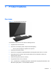
1 Product features Overview Figure 1-1 HP EliteOne 800 G1 All-in-One The HP EliteOne 800 G1 All-in-One offers the following features: ● Integrated All-in-One form factor ● Full HD IPS, LCD display (1920 x 1080) with LED backlighting ◦ 58.
2 ● Optional Tray-load HP SuperMulti DVD+/-RW SATA Optical Disc Drive, DVD-ROM disc drive, or Slim BDXL Blu-ray Writer ● Intel Q87 Express chipset – Intel vPro ● Two SODIMM slots with up to 16 GB of DDR3 SDRAM memory and dual channel memory support ● Intel integrated graphics ● DisplayPort video out (with audio) for second display support ● Optional MXM graphics card ● DP audio, DP to VGA/DVI/HDMI dongle support ● Integrated Gigabit Ethernet (Intel i217LM GbE LOM) ● Wireless connectivity (
Front components Figure 1-2 Front components Table 1-1 Front components Component Component 1 Webcam (optional) with privacy shutter 7 Mute speaker 2 Dual microphone array (optional) 8 Reduce volume 3 Webcam activity LED (with optional webcam) 9 Increase volume 4 16:9 widescreen LED-backlit LCD display 10 Mute microphone 5 Power LED 11 Decrease brightness 6 High-performance stereo speakers 12 Increase brightness Touch the icon area (7–12 above) to cause the icons to illuminate, th
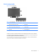
Side components Figure 1-3 Side components Table 1-2 Side components 4 Component Component 1 Hard disc drive activity LED 6 Headset/line out jack 2 HP 6-in-1 media card reader (optional) 7 Tray-load optical disc drive 3 USB 3.0 port, fast-charging 8 Optical disc drive eject button 4 USB 3.
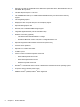
Rear components Figure 1-4 Rear components Table 1-3 Rear components Component Component 1 Access panel 8 (2) USB 3.0 ports 2 Access panel latches 9 RJ-45 Gigabit Ethernet port 3 Security lock slot 10 (2) USB 3.
Keyboard features Figure 1-5 Keyboard features Table 1-4 Keyboard features 6 Component Component 1 Sleep 6 Mute Volume 2 Fast Reverse 7 Decrease Volume 3 Play/Pause 8 Increase Volume 4 Stop 9 Function 5 Fast Forward Chapter 1 Product features
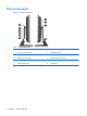
Positioning the computer This computer may be shipped with no stand, with a height-adjustable stand, or a tilt/swivel stand. The computer may be placed in the landscape position with the HP logo on the bottom bezel or it may be placed in the portrait position with the HP logo on the right side, as you face the computer. Figure 1-6 Supported and unsupported positions CAUTION: Positioning the computer with the HP logo on the top or on the left is not supported.
WARNING! If the height-adjustable/recline stand is installed, before laying the computer down for service, first grasp the sides of the display and raise the display to the highest position. Do not lay the computer down with the sliding stand in the low position. The stand may suddenly release, which could cause injury or damage to equipment.
Figure 1-10 Adjusting swivel Waking the computer To wake the HP EliteOne 800 G1 Touch All-in-One: ▲ To wake the computer from standby using the touch feature, swipe the screen or touch the screen and hold for at least two seconds. ▲ To wake the computer from hibernation, press and release the power button.
2 Hardware repair and upgrade Warnings and cautions Before performing upgrades be sure to carefully read all of the applicable instructions, cautions, and warnings in this guide. WARNING! To reduce the risk of personal injury from electrical shock, hot surfaces, or fire: Disconnect the power cord from the wall outlet and allow the internal system components to cool before touching. Do not plug telecommunications or telephone connectors into the network interface controller (NIC) receptacles.
Additional information For more information on removing and replacing hardware components, the Computer Setup utility, and troubleshooting, refer to the Maintenance and Service Guide (available in English only) for your computer model at http://www.hp.com. Removing and installing the rear port cover Removing the rear port cover 1. If a cable lock is installed on the rear of the unit, remove the lock. 2. Push the two tabs down, then rotate and lift the rear port cover off the computer.
Installing the rear port cover 1. Be sure that all cables are connected. 2. Hold the cover close to the computer (1) and line up the right edge of the cover with the right edge of the computer. Hook the six tabs on the bottom edge into the chassis, then press the top edge of the cover against the chassis until it locks into place (2). Figure 2-2 Installing the rear port cover Connecting and disconnecting power Connecting power 1. If the rear port cover is installed, remove the cover. 2.
4. Plug the power cord into the power connection on the rear of the computer (1). Figure 2-3 Connecting power 5. Plug the three-pronged power plug into a power outlet (2). 6. If the tilt/swivel stand is installed on the computer, attach the cable management cover: a. Position the cable management cover under the cables and align the cover hooks with the slots in the stand. b. insert the cover hooks into the stand and slide the cover down to secure it.
Disconnecting power 1. Remove all removable media, such as compact discs or USB flash drives, from the computer. 2. Turn off the computer properly through the operating system, then turn off any external devices. 3. Remove the cable lock, if one is installed on the rear of the computer. 4. If the rear port cover is installed, remove the cover. 5. Disconnect the power cord connector from the port. Installing a security lock The optional security lock enables you to secure your computer.
Installing an access panel security screw You may prevent access to internal components and ports by securing the access panel and rear port cover. Screw a T15 tamper-resistant Torx screw through the rear port cover and the access panel to prevent removal of either. Figure 2-6 Securing the access panel and rear port cover Synchronizing the optional wireless keyboard and mouse The optional wireless keyboard and mouse are easy to set up.
4. Insert the wireless receiver into a USB port on the computer. Figure 2-7 Installing the wireless receiver 5. Press and hold the Connect button on the wireless receiver for five seconds until the blue activity LED begins blinking. NOTE: When the blue activity LED begins blinking, you have 30 seconds to synchronize the mouse with the wireless receiver. 6. Press and release the Connect button on the bottom of the mouse.
Removing batteries from the optional wireless keyboard or mouse NOTE: The wireless keyboard and mouse are optional components. To remove batteries from the wireless keyboard, remove the battery door on the underside of the keyboard (1) and lift the batteries out of the battery compartment (2).
Attaching the computer to a mounting fixture You can remove the computer from the stand and install it on a wall, monitor arm, or other mounting fixture. There is a VESA mount under the computer stand that is used for mounting the computer. Table 2-1 Computer dimensions (without stand) Computer dimensions (without stand) Height 389.0 mm 15.3 in Width 560.0 mm 22.0 in Depth 55.3 mm 2.3 in 8.74 kg (EliteOne 800 G1 Touch AiO) 19.3 lb (EliteOne 800 G1 Touch AiO) 7.
Installing and removing a stand Two stands are available for the computer: ● Height-adjustable/recline stand ● Tilt/swivel stand Installing and removing a height-adjustable/recline stand (optional) Installing a height-adjustable/recline stand To install the stand: 1. Place the computer face down on a soft flat surface. HP recommends that you set down a blanket, towel, or other soft cloth to protect the bezel and screen surface from scratches or other damage. 2.
3. Tighten the four captive screws to secure the stand to the chassis. Figure 2-12 Securing the stand Removing a height-adjustable/recline stand To remove the stand: 1. Remove all removable media, such as compact discs or USB flash drives, from the computer. 2. Turn off the computer properly through the operating system, then turn off any external devices. 3. Disconnect the power cord from the power outlet and disconnect any external devices.
5. Place the computer face down on a soft flat surface. HP recommends that you set down a blanket, towel, or other soft cloth to protect the bezel and screen surface from scratches or other damage. WARNING! Before laying the computer down for service, first grasp the sides of the display and raise the display to the highest position. Do not lay the computer down with the sliding stand in the low position. The stand may suddenly release, which could cause injury or damage to equipment.
7. Lift the stand up and off the computer. Figure 2-15 Removing the stand Installing and removing a tilt/swivel stand (optional) Installing a tilt/swivel stand To install the stand: 1. Place the computer face down on a soft flat surface. HP recommends that you set down a blanket, towel, or other soft cloth to protect the bezel and screen surface from scratches or other damage. 2. Push the release button on the bottom of the stand and pull the back of the stand off. 3.
4. Tighten the captive screws to secure the stand to the chassis. Figure 2-17 Securing the stand 5. Align the top of the back of the stand with the stand, and press it into place, working along the sides until it is in place. Figure 2-18 Installing the back of the stand Removing a tilt/swivel stand To remove the stand: 1. Remove all removable media, such as compact discs or USB flash drives, from the computer. 2.
5. Place the computer face down on a soft flat surface. HP recommends that you set down a blanket, towel, or other soft cloth to protect the bezel and screen surface from scratches or other damage. 6. Push the release button (1) on the bottom of the stand and pull the back of the stand off (2) the computer. Figure 2-19 Removing the back of the stand 7. Push the base of the stand down (1), and loosen the captive screws securing the stand to the unit (2).
8. Lift the stand up and off the computer. Figure 2-21 Removing the stand Connecting a second display The DisplayPort connector on the rear of the computer allows you to connect a second display to the computer. If you are adding a second display that has a DisplayPort connector, then no DisplayPort video adapter is required. If you are adding a second display that does not have a DisplayPort connector, you can purchase a DisplayPort video adaptor from HP for your configuration.
3. If your second display has a DisplayPort connector, connect a DisplayPort cable directly between the DisplayPort connector on the rear of the computer and the DisplayPort connector on the second display.
4. If your second display does not have a DisplayPort connector, connect a DisplayPort video adapter to the DisplayPort connector of the computer. Then connect a cable (VGA, DVI. or HDMI, depending on your application) between the adapter and a second display. NOTE: When a DisplayPort adaptor is used, the rear port cover cannot be installed unless a DisplayPort extender cable is used in conjunction with the adaptor. Figure 2-24 Connecting a second display using a DisplayPort adapter 5.
Locating internal components The following sections contain procedures for removing and replacing these internal components: ● Memory ● Battery ● Hard disc drive, solid state drive, or self-encrypting drive ● Optical disc drive Figure 2-25 Locating internal components 28 Component Component 1 Optical disc drive 3 Memory 2 Hard disc drive 4 Battery Chapter 2 Hardware repair and upgrade
Removing and installing memory The computer comes with double data rate 3 synchronous dynamic random access memory (DDR3SDRAM) small outline dual inline memory modules (SODIMMs). SODIMMs The memory sockets on the system board can be populated with up to two industry-standard SODIMMs. These memory sockets are populated with at least one preinstalled SODIMM. To achieve the maximum memory support, you can populate the system board with up to 16 GB of memory.
Populating SODIMM sockets The system will automatically operate in single channel mode, dual channel mode, or flex mode, depending on how the SODIMMs are installed. Refer to the following table to identify the SODIMM channel locations. Table 2-2 Identifying SODIMM locations Location System board label Channel Lower Socket SODIMM1 Channel A Upper Socket SODIMM3 Channel B ● The system will operate in single channel mode if the SODIMM sockets are populated in one channel only.
6. Slide the access panel latches toward the edges of the unit, then slide the access panel toward the top of the computer until it slides off the unit. Figure 2-26 Removing the access panel 7. To remove a memory module, press outward on the two latches on each side of the SODIMM (1), then pull the SODIMM out of the socket (2).
8. To install a memory module, slide the SODIMM into the socket at approximately a 30° angle (1), then press the SODIMM down (2) so that the latches lock it in place. Figure 2-28 Installing a memory module NOTE: A memory module can be installed in only one way. Match the notch on the module with the tab on the memory socket. 9. To replace the access panel, set the panel on the back of the computer, slightly above the stand, and slide it down into place. Figure 2-29 Replacing the access panel 10.
Replacing the battery The battery is located on the system board on the lower right side of the fan. The battery that comes with the computer provides power to the real-time clock. When replacing the battery, use a battery equivalent to the battery originally installed in the computer. The computer comes with a 3-volt lithium coin cell battery. WARNING! The computer contains an internal lithium manganese dioxide battery. There is a risk of fire and burns if the battery is not handled properly.
6. Slide the access panel latches toward the edges of the chassis, then slide the access panel toward the top of the computer until it slides off the chassis. Figure 2-30 Removing the access panel The battery can now be seen on the lower right side of the fan. Figure 2-31 Locating the battery 7. 34 To release the battery from its holder, squeeze the metal clamp that extends above one edge of the battery. When the battery pops up, lift it out (1).
8. To insert the new battery, slide one edge of the replacement battery under the holder’s lip with the positive side up. Push the other edge down until the clamp snaps over the other edge of the battery (2). Figure 2-32 Removing and replacing a coin cell battery 9. To replace the access panel, set the panel on the back of the computer, slightly above the stand, and slide it down into place. Figure 2-33 Replacing the access panel 10. Reconnect the power cord and external devices. 11.
Replacing drives Replacing a hard disc drive The hard disc drive is located behind the access panel on the lower left side of the computer (when viewed from behind). The drive is housed in a removable cage. One or two 2.5-inch solid state drives (SSDs) or self-encrypting drives (SEDs) may be installed in the computer. If a single drive is installed, it must be installed in the primary (lower) position. ● Removing a 2.5-inch hard disc drive ● Installing a 2.5-inch hard disc drive Removing a 2.
7. Pull the latch next to the lower side of the 2.5-inch hard disc drive cage away from the cage to release it, then slide the cage toward the edge of the chassis and lift it out. Figure 2-35 Removing the 2.5-inch hard disc drive cage 8. If there is a second disc drive in the 2.5-inch cage, disconnect both cables from it. 9. Remove the four mounting screws from each 2.5-inch hard disc drive to be removed.
Installing a 2.5-inch hard disc drive 1. Insert the 2.5-inch hard disc drive into the drive cage. ● To install a primary hard disc drive, insert the drive into the lower position in the drive cage. Be sure to insert the end with the connectors first. NOTE: The primary drive is the lower position in the drive cage. If only one drive is to be installed, it must occupy this position. ● 2. To install a secondary hard disc drive, set the drive into the upper tray of the drive cage.
3. Fasten an upper 2.5-inch hard disc drive securely in place with the four standard screws that shipped with the drive. 4. Position the 2.5-inch drive cage above its final site with the hard disc drive connectors facing toward the center of the chassis. If the drive cage contains a secondary (upper) drive, locate the power and data cables next to the drive cage and connect them to the secondary drive. 5. Place the 2.
6. To replace the access panel, set the panel on the back of the computer, slightly above the stand, and slide it down into place. Figure 2-39 Replacing the access panel 7. Reconnect the power cord and external devices. 8. Lock any security devices that were disengaged when the access panel was removed. 9. Place the computer in the upright position. 10. Turn on the computer.
6. Slide the access panel latches toward the edges of the chassis, then slide the access panel toward the top of the computer until it slides off the chassis. Figure 2-40 Removing the access panel 7. Push and hold the tab (1) at the back of the optical disc drive enclosure while sliding the drive (2) out of the chassis.
8. Pull the latch off the optical disc drive. Figure 2-42 Removing the optical disc drive latch 9. Remove the cover from the adhesive strip on the new latch. Align the two pins on the latch with the holes in the new optical disc drive and press the latch onto the drive firmly. NOTE: You may reuse the latch removed from the old optical disc drive.
10. Align the new optical disc drive with the opening in the side of the computer. Push the drive in firmly until it snaps into place. NOTE: The optical disc drive can be installed in only one way. Figure 2-44 Installing the optical disc drive 11. To replace the access panel, set the panel on the back of the computer, slightly above the stand, and slide it down into place. Figure 2-45 Replacing the access panel 12. Reconnect the power cord and external devices. 13.
A Electrostatic discharge A discharge of static electricity from a finger or other conductor may damage system boards or other static-sensitive devices. This type of damage may reduce the life expectancy of the device. Preventing electrostatic damage To prevent electrostatic damage, observe the following precautions: ● Avoid hand contact by transporting and storing products in static-safe containers.
B Computer operating guidelines, routine care, and shipping preparation Computer operating guidelines and routine care Follow these guidelines to properly set up and care for the computer: ● Keep the computer away from excessive moisture, direct sunlight, and extremes of heat and cold. ● Operate the computer on a sturdy, level surface. Leave a 10.2-cm (4-inch) clearance on all vented sides of the computer to permit the required airflow.
damp cloth to gently wipe the screen surface. Never spray the cleaner directly on the screen surface. It may run behind the bezel and damage the electronics. ◦ Occasionally clean the air vents on all vented sides of the computer. Lint, dust, and other foreign matter can block the vents and limit the airflow. Optical disc drive precautions Be sure to observe the following guidelines while operating or cleaning the optical disc drive. ● Do not move the drive during operation.
Index A additional information 2.5-inch, removing 36 replacing 36 self-encrypting 36 solid state 36 types 36 height adjustment 7 height-adjustable/recline stand installing 19 removing 20 11 B battery replacement 33 C components front 3 internal 28 rear 5 side 4 computer operating guidelines 45 D DisplayPort video adapter, connecting 25 drive 2.5-inch, installing 38 2.
location 30 specifications 29 specifications, memory 29 stand height-adjustable/recline, installing 19 height-adjustable/recline, removing 20 tilt/swivel stand, installing 22 tilt/swivel stand, removing 23 swivel adjustment 8 synchronizing wireless keyboard and mouse 15 T tilt adjustment 8 tilt/swivel stand installing 22 removing 23 V ventilation guidelines 45 VESA mounting holes 18 W waking the computer 9 warnings and cautions 10 48 Index