
HP ENVY Notebook Intel Models 17-n100 17-n199 3D camera Models 17-r100 17-r199 (worldwide) 3D camera Models m7-r100 m7-r199 (North America) - Maintenance and Service Guide
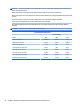
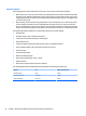
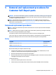
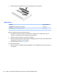
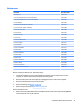
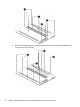
Table Of Contents
- Product description
- External component identification
- Illustrated parts catalog
- Removal and replacement procedures preliminary requirements
- Removal and replacement procedures for Customer Self-Repair parts
- Removal and replacement procedures for Authorized Service Provider parts
- Component replacement procedures
- Bottom cover
- Hard drive
- WLAN module
- Memory module
- USB board
- Fan
- Heat sink
- RTC battery
- Speakers (front)
- Subwoofer
- System board
- Solid State Drive
- Speaker (rear)
- LID board
- TouchPad assembly
- Fingerprint reader board (select products only)
- Power connector cable
- Display assembly – touch screen
- Display assembly – non-touch screen
- Component replacement procedures
- Computer Setup (BIOS), TPM, and HP Sure Start – Windows 10
- Using Setup Utility (BIOS) in Windows 8.1
- Using Setup Utility (BIOS) in Windows 7
- HP PC Hardware Diagnostics (UEFI) – Windows 10
- Using HP PC Hardware Diagnostics (UEFI) in Windows 8.1
- Backup and recovery – Windows 10
- Backing up, restoring, and recovering in Windows 8.1
- Backing up, restoring, and recovering in Windows 7
- Ubuntu Linux – Backing up, restoring, and recovering
- Specifications
- Power cord set requirements
- Recycling
- Index
3. Rotate the battery upward (3), and then remove the battery from the computer.
Optical drive
Description Spare part number
Optical Drive
DVD+/-RW Double-Layer SuperMulti 813784-001
Optical Drive
Blu-ray Disc R/RW with SuperMulti 813785-001
Before removing the optical drive, follow these steps:
1
. Shut down the computer. If you are unsure whether the computer is o or in Hibernation, turn the
computer on, and then shut it down through the operating system.
2
. Disconnect all external devices connected to the computer.
3
. Disconnect the power from the computer by rst unplugging the power cord from the AC outlet and then
unplugging the AC adapter from the computer.
4
. Remove the battery (see
Battery on page 27).
To remove the optical drive:
1
. Remove the screw covers (1) and then the Phillips PM2.5×7.0 screw (2) that secures the optical drive to
the computer.
28 Chapter 5 Removal and replacement procedures for Customer Self-Repair parts