
HP ENVY Notebook Intel Models 17-n100 17-n199 3D camera Models 17-r100 17-r199 (worldwide) 3D camera Models m7-r100 m7-r199 (North America) - Maintenance and Service Guide
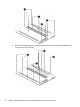
Table Of Contents
- Product description
- External component identification
- Illustrated parts catalog
- Removal and replacement procedures preliminary requirements
- Removal and replacement procedures for Customer Self-Repair parts
- Removal and replacement procedures for Authorized Service Provider parts
- Component replacement procedures
- Bottom cover
- Hard drive
- WLAN module
- Memory module
- USB board
- Fan
- Heat sink
- RTC battery
- Speakers (front)
- Subwoofer
- System board
- Solid State Drive
- Speaker (rear)
- LID board
- TouchPad assembly
- Fingerprint reader board (select products only)
- Power connector cable
- Display assembly – touch screen
- Display assembly – non-touch screen
- Component replacement procedures
- Computer Setup (BIOS), TPM, and HP Sure Start – Windows 10
- Using Setup Utility (BIOS) in Windows 8.1
- Using Setup Utility (BIOS) in Windows 7
- HP PC Hardware Diagnostics (UEFI) – Windows 10
- Using HP PC Hardware Diagnostics (UEFI) in Windows 8.1
- Backup and recovery – Windows 10
- Backing up, restoring, and recovering in Windows 8.1
- Backing up, restoring, and recovering in Windows 7
- Ubuntu Linux – Backing up, restoring, and recovering
- Specifications
- Power cord set requirements
- Recycling
- Index
6 Removal and replacement procedures for
Authorized Service Provider parts
CAUTION: Components described in this chapter should only be accessed by an authorized service provider.
Accessing these parts can damage the computer or void the warranty.
NOTE: HP continually improves and changes product parts. For complete and current information on
supported parts for your computer, go to http://partsurfer.hp.com, select your country or region, and then
follow the on-screen instructions.
Component replacement procedures
This chapter provides removal and replacement procedures for Authorized Service Provider only parts.
There are as many as 75 screws that must be removed, replaced, and/or loosened when servicing the
computer. Make special note of each screw size and location during removal and replacement.
NOTE: To remove the non-touch screen display, you do not need to remove the system board, see Display
assembly – non-touch screen on page 65. For the touch screen, the hinges are under the system board and
it must be removed, see Display assembly – touch screen on page 60.
30 Chapter 6 Removal and replacement procedures for Authorized Service Provider parts