
HP ENVY Notebook Intel Models 17-n100 17-n199 3D camera Models 17-r100 17-r199 (worldwide) 3D camera Models m7-r100 m7-r199 (North America) - Maintenance and Service Guide
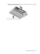
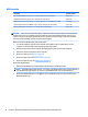
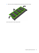
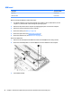
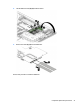
Table Of Contents
- Product description
- External component identification
- Illustrated parts catalog
- Removal and replacement procedures preliminary requirements
- Removal and replacement procedures for Customer Self-Repair parts
- Removal and replacement procedures for Authorized Service Provider parts
- Component replacement procedures
- Bottom cover
- Hard drive
- WLAN module
- Memory module
- USB board
- Fan
- Heat sink
- RTC battery
- Speakers (front)
- Subwoofer
- System board
- Solid State Drive
- Speaker (rear)
- LID board
- TouchPad assembly
- Fingerprint reader board (select products only)
- Power connector cable
- Display assembly – touch screen
- Display assembly – non-touch screen
- Component replacement procedures
- Computer Setup (BIOS), TPM, and HP Sure Start – Windows 10
- Using Setup Utility (BIOS) in Windows 8.1
- Using Setup Utility (BIOS) in Windows 7
- HP PC Hardware Diagnostics (UEFI) – Windows 10
- Using HP PC Hardware Diagnostics (UEFI) in Windows 8.1
- Backup and recovery – Windows 10
- Backing up, restoring, and recovering in Windows 8.1
- Backing up, restoring, and recovering in Windows 7
- Ubuntu Linux – Backing up, restoring, and recovering
- Specifications
- Power cord set requirements
- Recycling
- Index
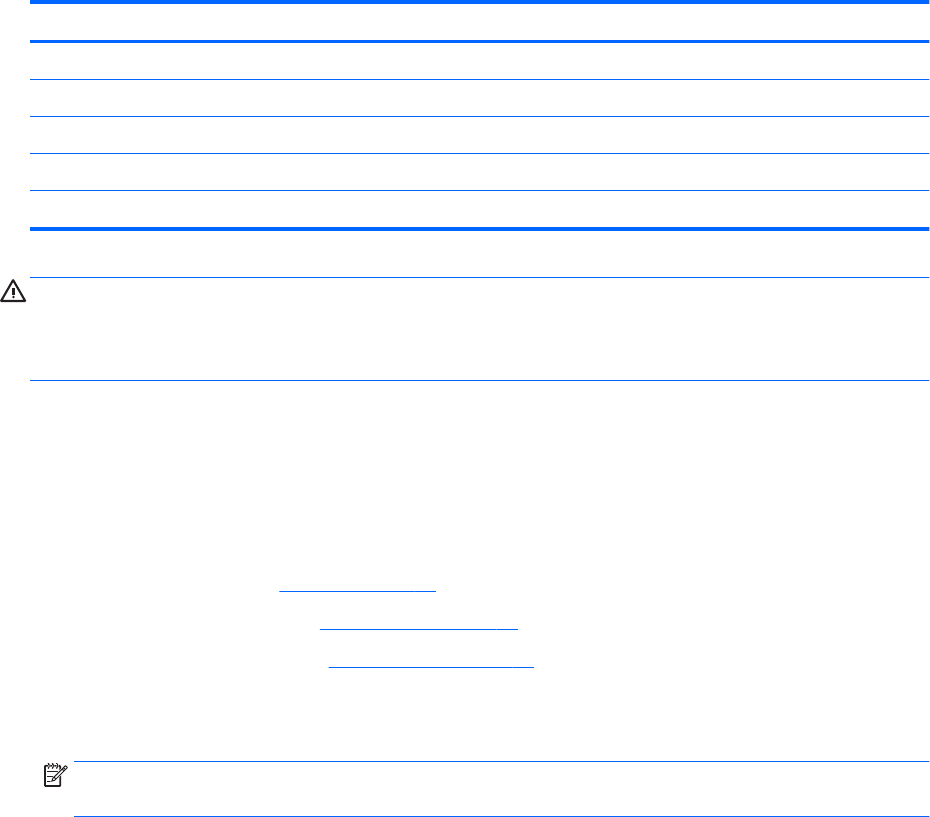
WLAN module
Description Spare part number
Intel Dual Band Wireless-AC 3160 802.11 ac 1x1 WiFi + Bluetooth 4.0 Combo Adapter 784644-005
Realtek RTL8723BE 802.11b/g/n 1x1 Wi-Fi + Bluetooth 4.0 Combo Adapter 792610-005
Intel Dual Band Wireless-AC 7265 802.11 ac 2x2 WiFi + Bluetooth 4.0 Combo Adapter (non vPRO) 793840-005
Intel Dual Band Wireless-N 7265BN 802.11 b/g/n 2x2 WiFi + Bluetooth 4.0 combo adaptor 793843-005
Intel Dual Band Wireless-AC 3165 802.11 ac 1x1 WiFi + BT 4.0 Combo Adapter 806723-005
CAUTION: To prevent an unresponsive system, replace the wireless module only with a wireless module
authorized for use in the computer by the governmental agency that regulates wireless devices in your
country or region. If you replace the module and then receive a warning message, remove the module to
restore device functionality, and then contact technical support.
Before removing the WLAN module, follow these steps:
1. Turn o the computer. If you are unsure whether the computer is o or in Hibernation, turn the
computer on, and then shut it down through the operating system.
2. Disconnect the power from the computer by unplugging the power cord from the computer.
3. Disconnect all external devices from the computer.
4. Remove the battery (see Battery on page 27).
5. Remove the optical drive (see Optical drive on page 28).
6. Remove the bottom cover (see Bottom cover on page 31).
Remove the WLAN module:
1. Disconnect the WLAN antenna cables (1) from the terminals on the WLAN module.
NOTE: The WLAN antenna cable labeled “1” connects to the WLAN module “Main” terminal labeled “1”.
The WLAN antenna cable labeled “2” connects to the WLAN module “Aux” terminal labeled “2”.
2. Remove the Phillips PM2.0×2.5 screw (2) that secures the WLAN module to the system board. (The
WLAN module tilts up.)
36 Chapter 6 Removal and replacement procedures for Authorized Service Provider parts