
HP ENVY Notebook Intel Models 17-n100 17-n199 3D camera Models 17-r100 17-r199 (worldwide) 3D camera Models m7-r100 m7-r199 (North America) - Maintenance and Service Guide
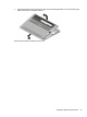
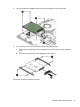
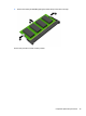
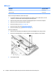
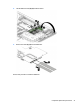
Table Of Contents
- Product description
- External component identification
- Illustrated parts catalog
- Removal and replacement procedures preliminary requirements
- Removal and replacement procedures for Customer Self-Repair parts
- Removal and replacement procedures for Authorized Service Provider parts
- Component replacement procedures
- Bottom cover
- Hard drive
- WLAN module
- Memory module
- USB board
- Fan
- Heat sink
- RTC battery
- Speakers (front)
- Subwoofer
- System board
- Solid State Drive
- Speaker (rear)
- LID board
- TouchPad assembly
- Fingerprint reader board (select products only)
- Power connector cable
- Display assembly – touch screen
- Display assembly – non-touch screen
- Component replacement procedures
- Computer Setup (BIOS), TPM, and HP Sure Start – Windows 10
- Using Setup Utility (BIOS) in Windows 8.1
- Using Setup Utility (BIOS) in Windows 7
- HP PC Hardware Diagnostics (UEFI) – Windows 10
- Using HP PC Hardware Diagnostics (UEFI) in Windows 8.1
- Backup and recovery – Windows 10
- Backing up, restoring, and recovering in Windows 8.1
- Backing up, restoring, and recovering in Windows 7
- Ubuntu Linux – Backing up, restoring, and recovering
- Specifications
- Power cord set requirements
- Recycling
- Index

Fan
NOTE: The fan spare part kit includes replacement thermal materials.
Description Spare part number
Fan 813798-001
NOTE: To properly ventilate the computer, allow at least 7.6 cm (3.0 in) of clearance on the left side of the
computer. The computer uses an electric fan for ventilation. The fan is controlled by a temperature sensor and
is designed to turn on automatically when high temperature conditions exist. These conditions are aected by
high external temperatures, system power consumption, power management/battery conservation
congurations, battery fast charging, and software requirements. Exhaust air is displaced through the
ventilation grill located on the left side of the computer.
Before removing the fan/heat sink assembly, follow these steps:
1. Shut down the computer. If you are unsure whether the computer is o or in Hibernation, turn the
computer on, and then shut it down through the operating system.
2. Disconnect all external devices connected to the computer.
3. Disconnect the power from the computer by rst unplugging the power cord from the AC outlet and then
unplugging the AC adapter from the computer.
4. Remove the battery (see Battery on page 27).
5. Remove the optical drive (see Optical drive on page 28).
6. Remove the bottom cover (see Bottom cover on page 31).
To remove the fan:
1. Position the computer upright and open it.
2. Remove the two Phillips PM3.0×3.0 screws (1) that secure the fan to the computer.
3. Disconnect the fan cable (2) from the system board.
42 Chapter 6 Removal and replacement procedures for Authorized Service Provider parts