
HP ENVY Notebook Intel Models 17-n100 17-n199 3D camera Models 17-r100 17-r199 (worldwide) 3D camera Models m7-r100 m7-r199 (North America) - Maintenance and Service Guide
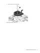
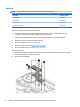
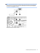
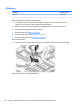
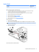
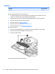
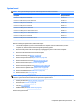
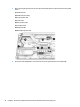
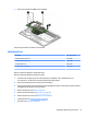
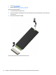
Table Of Contents
- Product description
- External component identification
- Illustrated parts catalog
- Removal and replacement procedures preliminary requirements
- Removal and replacement procedures for Customer Self-Repair parts
- Removal and replacement procedures for Authorized Service Provider parts
- Component replacement procedures
- Bottom cover
- Hard drive
- WLAN module
- Memory module
- USB board
- Fan
- Heat sink
- RTC battery
- Speakers (front)
- Subwoofer
- System board
- Solid State Drive
- Speaker (rear)
- LID board
- TouchPad assembly
- Fingerprint reader board (select products only)
- Power connector cable
- Display assembly – touch screen
- Display assembly – non-touch screen
- Component replacement procedures
- Computer Setup (BIOS), TPM, and HP Sure Start – Windows 10
- Using Setup Utility (BIOS) in Windows 8.1
- Using Setup Utility (BIOS) in Windows 7
- HP PC Hardware Diagnostics (UEFI) – Windows 10
- Using HP PC Hardware Diagnostics (UEFI) in Windows 8.1
- Backup and recovery – Windows 10
- Backing up, restoring, and recovering in Windows 8.1
- Backing up, restoring, and recovering in Windows 7
- Ubuntu Linux – Backing up, restoring, and recovering
- Specifications
- Power cord set requirements
- Recycling
- Index
System board
NOTE: The system board spare part kit includes replacement thermal material.
Description Spare part number
Intel Core i7-5500U processor 940M 2 GB 813681-xxx
Intel Core i7-5200U discrete processor 940M 2 GB 813680-xxx
Intel Core i7-5500U processor 950M 2 GB 813682–xxx
Intel Core i5-6200U processor 940M 2 GB 829065-xx1
Intel Core i7-6700HQ processor 950M 4 GB 829066-xx1
Intel Core i7-6700HQ processor 950M 4 GB 3D camera 829068-xx1
Intel Core i7-6700HQ processor 940M 4 GB 3D camera 829069-xx1
Intel Core i7-6500U processor 940M 2 GB 829070-xx1
Intel Core i7-6500U processor 940M 2 GB 3D camera 837769-xx1
Before removing the system board, follow these steps:
1. Turn o the computer. If you are unsure whether the computer is o or in Hibernation, turn the
computer on, and then shut it down through the operating system.
2. Disconnect the power from the computer by unplugging the power cord from the computer.
3. Disconnect all external devices from the computer.
4. Remove the battery (see Battery on page 27).
5. Remove the optical drive (see Optical drive on page 28).
6. Remove the bottom cover (see Bottom cover on page 31).
7. Remove the hard drive (see Hard drive on page 34).
8. Remove the front speakers (see Speakers (front) on page 47).
9. Remove the rear speakers (see Speaker (rear) on page 53).
10. Remove the USB board (see USB board on page 40).
11. Remove the fan (see Fan on page 42).
NOTE: When replacing the system board, be sure that the following components are removed from the
defective system board and installed on the replacement system board:
●
Memory module (see Memory module on page 38)
●
Heat sink (see Heat sink on page 44)
●
Fan (see Fan on page 42)
●
WLAN module (see WLAN module on page 36)
Remove the system board:
Component replacement procedures 49