
HP ENVY Notebook Intel Models 17-n100 17-n199 3D camera Models 17-r100 17-r199 (worldwide) 3D camera Models m7-r100 m7-r199 (North America) - Maintenance and Service Guide
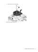
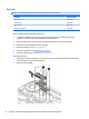
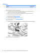
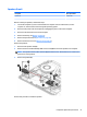
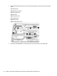
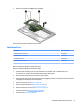
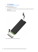
Table Of Contents
- Product description
- External component identification
- Illustrated parts catalog
- Removal and replacement procedures preliminary requirements
- Removal and replacement procedures for Customer Self-Repair parts
- Removal and replacement procedures for Authorized Service Provider parts
- Component replacement procedures
- Bottom cover
- Hard drive
- WLAN module
- Memory module
- USB board
- Fan
- Heat sink
- RTC battery
- Speakers (front)
- Subwoofer
- System board
- Solid State Drive
- Speaker (rear)
- LID board
- TouchPad assembly
- Fingerprint reader board (select products only)
- Power connector cable
- Display assembly – touch screen
- Display assembly – non-touch screen
- Component replacement procedures
- Computer Setup (BIOS), TPM, and HP Sure Start – Windows 10
- Using Setup Utility (BIOS) in Windows 8.1
- Using Setup Utility (BIOS) in Windows 7
- HP PC Hardware Diagnostics (UEFI) – Windows 10
- Using HP PC Hardware Diagnostics (UEFI) in Windows 8.1
- Backup and recovery – Windows 10
- Backing up, restoring, and recovering in Windows 8.1
- Backing up, restoring, and recovering in Windows 7
- Ubuntu Linux – Backing up, restoring, and recovering
- Specifications
- Power cord set requirements
- Recycling
- Index
●
Fan (see Fan on page 42)
●
WLAN module (see WLAN module on page 36)
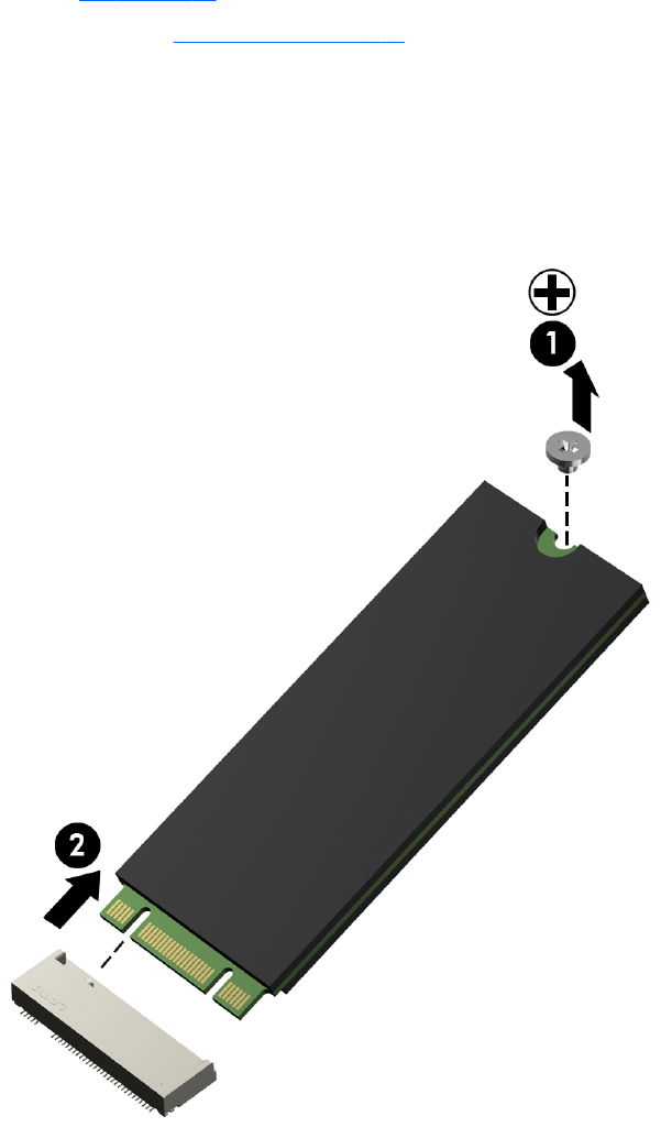
Remove the solid-state drive:
1. Turn the system board upside down.
2. Remove the Phillips.screw (1) that secures the solid-state drive to the system board. (The solid-state
drive tilts up).
3. Remove the solid-state drive (2).
Reverse this procedure to install the solid-state drive.
52 Chapter 6 Removal and replacement procedures for Authorized Service Provider parts