
HP ENVY Notebook Intel Models 17-n100 17-n199 3D camera Models 17-r100 17-r199 (worldwide) 3D camera Models m7-r100 m7-r199 (North America) - Maintenance and Service Guide
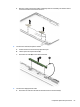
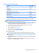
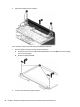
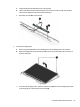
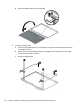
Table Of Contents
- Product description
- External component identification
- Illustrated parts catalog
- Removal and replacement procedures preliminary requirements
- Removal and replacement procedures for Customer Self-Repair parts
- Removal and replacement procedures for Authorized Service Provider parts
- Component replacement procedures
- Bottom cover
- Hard drive
- WLAN module
- Memory module
- USB board
- Fan
- Heat sink
- RTC battery
- Speakers (front)
- Subwoofer
- System board
- Solid State Drive
- Speaker (rear)
- LID board
- TouchPad assembly
- Fingerprint reader board (select products only)
- Power connector cable
- Display assembly – touch screen
- Display assembly – non-touch screen
- Component replacement procedures
- Computer Setup (BIOS), TPM, and HP Sure Start – Windows 10
- Using Setup Utility (BIOS) in Windows 8.1
- Using Setup Utility (BIOS) in Windows 7
- HP PC Hardware Diagnostics (UEFI) – Windows 10
- Using HP PC Hardware Diagnostics (UEFI) in Windows 8.1
- Backup and recovery – Windows 10
- Backing up, restoring, and recovering in Windows 8.1
- Backing up, restoring, and recovering in Windows 7
- Ubuntu Linux – Backing up, restoring, and recovering
- Specifications
- Power cord set requirements
- Recycling
- Index
Display assembly – non-touch screen
Component Spare part number
Bezel 813790-001
Webcam module 812714-001
Raw display panel (17.3; includes touch panel, touch board, bezel, rubber supports, display cable,
webcam, and screws)
813808-001
Hinges (left and right, includes screw and brackets) 813801-001
Antennas (includes wireless antenna cables and transceivers) 813786-001
Display/webcam cable 813791-001
Display enclosure 813788-001
Display enclosure 3D camera 832350-001
To remove the display assembly and access the display assembly subcomponents, follow these steps:
NOTE: To remove the non-touch screen display, you do not need to remove the system board. For the touch
screen, the hinges are under the system board and it must be removed.
1. Turn o the computer. If you are unsure whether the computer is o or in Hibernation, turn the
computer on, and then shut it down through the operating system.
2. Disconnect the power from the computer by unplugging the power cord from the computer.
3. Disconnect all external devices from the computer.
4. Remove the battery (see Battery on page 27).
5. Remove the optical drive (see Optical drive on page 28).
6. Remove the bottom cover (see Bottom cover on page 31).
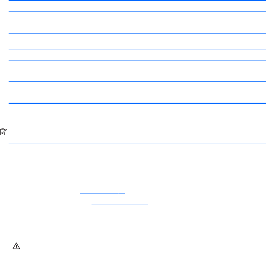
Remove the display assembly:
1. Open the computer and position the computer with the display hanging over the edge of a tablet.
CAUTION: Be sure to support the display as you remove the screws to avoid the display falling and
sustaining damage.
2. Remove the six Phillips PM2.5×4.0 screws (1) (three on each hinge) that secure the display assembly to
the computer.
3. Remove the three broadhead Phillips PM2.5×2.5 screws (2) (two on the right hinge, one of the left
hinge) that secure the display assembly to the computer.
Component replacement procedures 65