HP Server Remote Management Card User Guide for tc3100 and tc4100 Servers Printed February 2002
Notice The information contained in this document is subject to change without notice. Hewlett-Packard makes no warranty of any kind with regard to this material, including, but not limited to, the implied warranties of merchantability and fitness for a particular purpose. Hewlett-Packard shall not be liable for errors contained herein or for incidental or consequential damages in connection with the furnishing, performance, or use of this material.
Contents 1 Quick Start ........................................................................................................1 2 Introducing the HP Server Remote Management Card ................................5 How the HP Server Remote Management Card Works ....................................6 Package Contents..............................................................................................7 Documentation .......................................................................................
Contents 6 Windows Graphics Console Redirection Using pcAnywhere...................39 Installing pcAnywhere on the Server ...............................................................40 Installing pcAnywhere Server Software.......................................................40 Configuring pcAnywhere Server Software...................................................41 Installing pcAnywhere on the Remote Client ...................................................
Contents FCC Radio Frequency Emissions Statements ......................................... 102 Notice for Taiwan .......................................................................................... 103 DECLARATION OF CONFORMITY (US and EU)........................................ 104 Technical Support ......................................................................................... 105 U.S. and Canada ......................................................................................
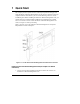
1 Quick Start This chapter provides a quick overview of the steps required for setting up and using the HP Server Remote Management Card. If you have experience setting up computer hardware and software, you can use the following section as a brief installation guide. Before installing the HP Server Remote Management Card, you must already have completed initial installation and configuration of your HP Server.
Chapter 1 Quick Start 2. Install the HP Server Remote Management Card in PCI slot 6. 3. Connect the free end of the 50-pin ribbon cable to the 50-pin connector on the server's system board. The connector is keyed. IMPORTANT After you have installed the HP Server Remote Management Card, you must flash the server system BIOS. Flashing the BIOS populates the sensor data repository on the Remote Management Card. This is required to make environmental data available to the Management Card’s web interface.
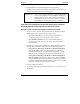
Chapter 1 Quick Start If you plan to connect to the HP Server Remote Management Card via the LAN: ◊ Verify that the client has TCP/IP software is installed and it is properly configured for your LAN (client's IP address, subnet mask, and gateway) by checking the TCP/IP protocol properties from the Network program in the control panel. ◊ Verify your client's browser's proxy settings.
Chapter 1 Quick Start ◊ If connecting via modem, enter the card's PPP IP address that you entered when you ran the HP Server Remote Management Card BIOS setup (for example: http://xxx.xxx.xxx.xxx/). Once you are connected, the HP Server Remote Management Card Identity page is displayed in your browser window (see Figure 5-1). 4. Click the Configuration Tab. The login prompt is displayed. 5. In the User Name field, enter a valid administrator name. For your first login, the factory default name is ADMIN.
2 Introducing the HP Server Remote Management Card The HP Server Remote Management Card combines an intelligent PCI card and integrated software that provides powerful remote server management. Management capabilities include server status monitoring, configurable event notification, and diagnostic features. The card's remote management capabilities are accessed using standard web browser software. The HP Server Remote Management Card consists of: • HP Server Remote Management Card.
Chapter 2 Introducing HP Server Remote Management Card How the HP Server Remote Management Card Works The HP Server Remote Management Card operates independent of the server. It has its own processor chip, a serial and LAN port, and interface. These are completely separate from the server and the server's Network Operating System (NOS). The benefit to network administrators is comprehensive remote server management, even in the event of a downed server.
Chapter 2 Introducing HP Server Remote Management Card Figure 2-1.
Chapter 2 Introducing HP Server Remote Management Card • The HP Server Remote Management Card web interface online help, which describes all aspects of the user interface including how to use the HP Server Remote Management Card to manage your network server. • pcAnywhere online documentation. The complete pcAnywhere User Guide is in Adobe Acrobat PDF format on the HP Netserver Navigator CD in the \util\pca32\xx\ subdirecory (where xx represents a two letter abbreviation for your local language).
Chapter 2 Introducing HP Server Remote Management Card • TFTP: Trivial File Transfer Protocol. This file transfer protocol allows PUT and GET operations with absolute file names and does not require user authentication. The HP Server Remote Management Card uses TFTP to implement firmware updates and remote boots. Who Should Use This Guide This guide is designed for system administrators and people who are familiar with installing, managing, and troubleshooting servers on a network.
Chapter 2 Introducing HP Server Remote Management Card if, for example, there has been a critical hardware failure. If text remote control is enabled during server reboot, the actual bootup screens can be viewed at a remote site. Remote configuration. An administrator at a remote client can reconfigure the HP Server Remote Management Card and change features such as notification actions. An administrator can also change user and administrator permissions without having to be at the server.
Chapter 2 Introducing HP Server Remote Management Card Event notification. The HP Server Remote Management Card notifies designated users when an event occurs that has been specified for notification. Using Remote Control notification, an administrator's valuable time is freed from constant surveillance of the server, and server downtime is kept to a minimum.
Chapter 2 Introducing HP Server Remote Management Card ROM (see Appendix C for details). When available, new firmware versions can be obtained from the HP web site. SNMP support. The HP Server Remote Management Card includes SNMP support embedded in firmware on the Remote Control card. SNMP queries (MIBII) provide seamless integration with any SNMP management platform including HP Toptools and HP OpenView.
Chapter 2 Introducing HP Server Remote Management Card • A tc3100 or tc4100 HP Server with PCI slot 6 available. • The server must also have been initially set up with a Network Operating System and the HP Server SNMP agents installed. The HP Server Remote Management Card uses these agents to perform certain functions.
Chapter 2 Introducing HP Server Remote Management Card • MS Windows NT or Windows 95, 98 ME or 2000 Dial-up Networking installed. For non-Windows platforms, suitable PPP software installed. • A supported web browser (see below) • pcAnywhere Version 8.0 or above for Windows NT 4.0 and pcAnywhere 9.
3 Hardware Installation and Configuration This chapter provides instructions for installing the HP Server Remote Management Card in a server and setting up a hardware connection that permits remote management of the server. (See Chapter 4 for information on setting up the HP Server Remote Management Card management software.
Chapter 3 1. Hardware Installation and Configuration Locate the 50-pin connector on the HP Server Remote Management Card. Figure 3-1: Locating the 50-pin Connector 2. Plug the end of the 50-pin ribbon that is labeled “To Card” into the card’s connector. 3. If additional cable is needed, order HP Part Number P3537-63010. NOTE The ribbon cable is keyed to prevent incorrect cable connection.
Chapter 3 Hardware Installation and Configuration Server is powered down. Serious injury may result if this warning is not observed. 2. You must plug the Remote Management Card into slot 6. Connecting the 50-pin Ribbon Cable to the Server After you have physically installed the HP Server Remote Management Card into slot 6 of your server, you must cable the card to the server's system board. One end of the supplied ribbon cable should already be connected to the Remote Control Card (see previous section).
Chapter 3 IMPORTANT Hardware Installation and Configuration After you have installed the HP Server Remote Management Card, you should install the Visual Diagnostic Panel that was shipped with the Remote Management Card. Refer to Appendix I for instructions. Flashing the Server's System BIOS After you have installed the HP Server Remote Management Card, you must flash the server system BIOS. Flashing the BIOS populates the sensor data repository on the Remote Management Card.
Chapter 3 Hardware Installation and Configuration configured. Proceed to the next chapter for detailed instructions on how to set up a remote connection to the HP Server Remote Management Card.
4 Setting Up the Remote Connection This chapter describes how to cable and configure the remote communications link to the HP Server Remote Management Card (LAN or modem). Once communications have been established, you may control your HP Server using the HP Server Remote Management Card web interface.
Chapter 4 Setting Up the Remote Connection section) to configure a communications link between the HP Server Remote Management Card and a remote client. Running the HP Server Remote Management Card BIOS Setup Program The HP Server Remote Management Card includes its own on-board processor that provides remote access and server supervision even if the server's power and operating system are not functional.
Chapter 4 Setting Up the Remote Connection The displayed value on any of the setting screens is updated as soon as an entered value is validated. LAN Configuration For a remote connection to the HP Server Remote Management Card via LAN, the LAN Settings screen is used to set up the connector on the card. If you are not sure how to set network parameters, contact your network administrator for the correct network settings.
Chapter 4 Setting Up the Remote Connection time expires. As long as the card does automatic renewing in time, it will not lose the leased IP Address. However, if the card is switched off, and remains off past the lease renewal date, it will lose its lease on the IP Address and will need to obtain a new one. The Ethernet settings may be customized for your network. Normally, you would enable Auto-Negotiation.
Chapter 4 Setting Up the Remote Connection To use the remote boot feature: 1. Set Remote Boot to "on." Note that once this is set, the Server will continue to attempt to boot off a remote boot image until you go back into the HP Server Remote Management Card BIOS setup program and set this option to "off." 2. Define the filename of the boot image. 3. Enter the IP Address of the TFTP server where the image file is located. 4.
Chapter 4 Setting Up the Remote Connection Figure 4-6. Remote Connection via the LAN To enable remote connection over your local area network, LAN settings must have been defined in the card's BIOS setup program (see previous section). Remote Client Configuration (LAN) Your remote client should already be set up and connected to your local area network.
Chapter 4 Setting Up the Remote Connection Phone jack Modem cable Remote Client PC RJ-11 cable Modem Phone jack Modem Server Figure 4-7. Remote Connection Through an External Modem NOTE HP recommends that you supply power to your external modem from an Uninterruptible Power Supply (UPS), so that you can be notified in case of an AC line power failure. Remote Client Configuration (PPP/Dial-Up Networking) This section describes using dial-up networking for a Windows NT 4.0 client.
Chapter 4 Setting Up the Remote Connection ◊ Click Advanced. Then add the following string in the "extra settings" field: x3&c0&d0 NOTE The dialback feature cannot function properly if you do not enter this string in the Extra Settings field as indicated. 3. Configure Dial-Up Networking by double-clicking the "My Computer" icon and then "Dial-Up Networking.
Chapter 4 Setting Up the Remote Connection 6. Click the "Server" tab to specify the dial-up server type, network protocols, and compression. Make sure your settings match the following figure. (If you have Windows 95, make sure you do not check the "Login to network" option.) Figure 4-9.
Chapter 4 Setting Up the Remote Connection 7. Click the "TCP/IP Settings" button (see Figure 4-10). Select the "Server assigned IP address" option. The client will automatically get an IP Address from the HP Server Remote Management Card. Check "Specify name server addresses" and make sure all DNS and WINS entry fields are set to zero (0). Uncheck "Use default gateway on remote network." Click OK. NOTE The card derives the address using the PPP IP address of the card which it increments by "1".
Chapter 4 Setting Up the Remote Connection 8. Click the "Script" tab. To expedite the HP Server Remote Management Card login process, use the script provided by HP included on the HP Netserver Navigator CD in \ttrc\us\ttrc.scp. Copy this script file to your remote client and enter that path in the script dialog box. Figure 4-11. Configure Script If you do not wish to use the script, select "Pop up a terminal window" instead. 9. Click the "Security" tab and select "accept only encrypted authentication".
5 Using the Remote Management Card Web Interface After you've installed, cabled, and configured the HP Server Remote Management Card using the card's BIOS setup program, you are ready to set options for the HP Server Remote Management Card using the Remote Management Card's management software.
Chapter 5 Logging In and Using the HP Server Remote Management Card Web Interface 1. If you are using a modem (PPP) at the remote client (skip to step 2 if you are not), make your connection using the Dial-Up Networking program. Once connected, you will see a modem connection icon on the task bar of your desktop. 2. At the remote client, start your web browser software. Make sure that the proxy settings for your browser have been correctly set.
Chapter 5 Logging In and Using the HP Server Remote Management Card Web Interface Figure 5-1. Example: HP Server Remote Management Card Identity Page 4. Click the Configuration tab. The login prompt is displayed. 5. In the User Name field, enter a valid administrator name. For your first login, the factory default user name is ADMIN.
Chapter 5 Logging In and Using the HP Server Remote Management Card Web Interface 6. At the password prompt, enter the password that belongs to the administrator name. For your first login, the factory default password is ADMIN. NOTE The user ID and the access password for the HP Server Remote Management Card software are case sensitive. CAUTION To avoid a potential security breach allowing someone to log in using the defaults, your first task should be to set up an administrator for the card.
Chapter 5 Logging In and Using the HP Server Remote Management Card Web Interface • Status. Provides an Event Log and access to environmental data, including voltage and temperature readings at the server. • Configuration. This is where you set up information about event management (how you will be notified of problems), add users, configure information about the server, and configure information about the card, including LAN and PPP assignments.
6 Windows Graphics Console Redirection Using pcAnywhere For Server systems running Microsoft Windows NT 4.0 or Windows 2000, you can redirect the server's graphics console to a remote PC client to remotely perform operations as if you were sitting at the server. To do this, you must install pcAnywhere software. If you are using the card's LAN connection, you only need to install pcAnywhere on the server.
Chapter 6 Setting Up NT Graphics Console Redirection Using pcAnywhere Installing pcAnywhere on the Server To enable console redirection (the ability to redirect what's graphically displayed on your server) either over the LAN or via modem, you must first install the pcAnywhere host software, included with your system, on your HP Server. NOTE Remember that the HP Server Remote Management Card software license authorizes a single administrator for each copy of software (including Symantec's pcAnywhere).
Chapter 6 Setting Up NT Graphics Console Redirection Using pcAnywhere 4. Run the pcAnywhere setup program. From the Windows Start menu, click "Run" and browse to the setup program's location: x:\util\pca32\language\disk1\setup.exe where x: is the letter of your CD-ROM drive and language is the two letter acronym for your local language (example: us=English, fr=French, ge=German, it=Italian, sp=Spanish). Follow the on-screen setup instructions. 5. When setup is complete, you are prompted to restart.
Chapter 6 Setting Up NT Graphics Console Redirection Using pcAnywhere 3. To make a new connection item for your server, double-click the "Add Be a Host PC Item". 4. Configure the connection item for LAN or modem use. ◊ LAN connection: Select TCP/IP as the connection device. ◊ Modem connection: You will be prompted for a Host Name and connection device. Select the COM port (not modem) assigned by the HP Server Remote Management Card's serial driver (see previous section).
Chapter 6 NOTE Setting Up NT Graphics Console Redirection Using pcAnywhere You can configure the pcAnywhere host to wait for both a modem and LAN connection by checking both a COM port and TCP/IP in the host icon's "Properties." 7. From the Properties menu, click the Settings tab and check the "Launch with Windows" and "Run minimized" checkboxes. Click OK to return to the main program window. 8. If you want to rename the connection item you just created, right-click the connection item and click Rename.
Chapter 6 Setting Up NT Graphics Console Redirection Using pcAnywhere Console Redirection Over a LAN Though pcAnywhere does need to be installed on the server, you do not need to install pcAnywhere on your remote console if you are using Console Redirection over the LAN. pcAnywhere Express is already built into the HP Server Remote Management Card (but only supports a LAN connection). You may skip to the "Using NT Graphics Console Redirection" section later in this chapter.
Chapter 6 Setting Up NT Graphics Console Redirection Using pcAnywhere 2. At the pcAnywhere main screen, click the Remote Control button. You will see the Remote Control connection items displayed. Figure 6-4. pcAnywhere "Remote Control" Connection Items 3. Create a new connection item to access your HP Server by double-clicking the "Add Remote Control Item". An installation Wizard prompts you for information needed to set up a new connection item. 4.
Chapter 6 Setting Up NT Graphics Console Redirection Using pcAnywhere 8. Enter the phone number of the HP Server Remote Management Card's modem, then click Next. 9. Uncheck "Automatically begin remote control session upon Wizard completion", then click Finish. Customizing Your Connection Items If you want to rename a connection item, right-click it, select Rename, and type in a new name. You can also copy, paste, and reconfigure a connection item to create an icon for each server you manage.
Chapter 6 Setting Up NT Graphics Console Redirection Using pcAnywhere 5. Start pcAnywhere. Double-click the remote control connection item for the server's Remote Management Card. pcAnywhere connects to the server and begins redirecting the NT console. For more information on using Windows NT console redirection, or for details about pcAnywhere features, refer to the online pcAnywhere User Guide.
7 Troubleshooting This chapter provides some guidelines for troubleshooting the HP Server Remote Management Card. Different sections highlight difficulties related to: • Installation problems • Paging concerns • Remote client issues Problems with Installation The HP Server Remote Management Card does not respond. Make sure that the HP Server Remote Management Card is securely seated in a PCI slot. Make sure that the 50-pin cable is connected.
Chapter 7 Troubleshooting If your pager service generates repetitive tones when it answers, the HP Server Remote Management Card modem may interpret the tones as a busy signal and attempt to re-dial. To prevent this, change the X4 command in the modem initialization string to X0 (blind dialing).
Chapter 7 Troubleshooting 20204 TAP: No message go ahead Event code 20204 occurs when the Terminal Logon is not accepted. This indicates that: 1. Your terminal has required more information than the HP Server Remote Management Card is configured to send. 2. Your paging service provider is not completely adhering to the alphanumeric paging protocols. If this appears to be the case, call HP Technical Support. 3. It is also possible that you are not dialing the correct modem access number.
Chapter 7 Troubleshooting Remote Client I cannot log into the HP Server Remote Management Card from the remote client. Are you entering the correct password? The login name and password are case sensitive. The factory default login name is ADMIN. Likewise, the factory default login password is ADMIN. I can no longer communicate with the HP Server Remote Management Card from the remote client. If DHCP is enabled for the HP Server Remote Management Card, the IP address on the card may have changed.
Chapter 7 Troubleshooting user from monopolizing access, especially when the connection is forgotten. This automatic logout feature is not adjustable. The keys I type from the remote client do not appear on the server screen. Type in the keyboard lock password to unlock the keyboard. The keyboard will remain unlocked until the next system reboot. If the password does not enable the keyboard, try toggling the Numlock key at the server to enable the numeric keypad.
Chapter 7 Troubleshooting I forgot my password and can no longer log into the card. If you are the HP Server Remote Management Card administrator and have forgotten your password, there is a special utility on the HP Netserver Navigator CD that will allow you to reset the HP Server Remote Management Card user database back to the factory defaults (Login=ADMIN, Password=ADMIN).
A Event Codes The table below describes the event codes that can be listed in the event log and optionally directed to specified users via e-mail or pager. When the HP Server Remote Management Card sends notification about a server event, it includes the server identifying number and a five-digit code identifying the event. (If you use email or a TAP pager, you will receive the server name and some descriptive text as well.
Appendix A Event Codes Pager Code Server Event 002XX Voltage sensor crossed lower non-recoverable threshold CRITICAL 002XX A measured voltage in the server has gone outside the factory specified upper voltage range. WARNING 002XX A measured voltage in the server has gone far outside the factory specified upper voltage range.
Appendix A Event Codes Pager Code Server Event 00705 Configuration Error in a Processor Slot CRITICAL 00707 Processor failure CRITICAL 00708 Processor (#) Disabled CRITICAL 00709 Processor or Terminator was not detected CRITICAL 00717 Processor problem CRITICAL 00718 The Processor in the indicated slot has been disabled by the BIOS. CRITICAL 00719 A single or multiple ECC Error has been detected on the P6 bus.
Appendix A Event Codes Pager Code Server Event Severity 00905 Power Supply Subsystem soft failure CRITICAL 00906 Power Supply Subsystem: Not enough Power Supply Units detected. CRITICAL 00906 Power Supply Subsystem: Not enough Power Supply Units detected CRITICAL or trouble powering up or down. 00906 Power Supply Subsystem: Not enough Power Supply Units detected CRITICAL or trouble powering up or down.
Appendix A Event Codes Pager Code Server Event Severity 01601 Too many errors of this type in time period INFORMATIONAL 01602 Event log cleared. INFORMATIONAL 01620 Event log getting full.
Appendix A Event Codes Pager Code Server Event Severity 02101 SCSI Duplex Board has been inserted INFORMATIONAL 02502 Cache Protocol and Parity error CRITICAL 02516 ACPI hardware failure WARNING 0274X Hot Swap Cage: SCSI Bus type has changed WARNING 0274X Hot Swap Cage: SCSI cable removed WARNING 0274X Hot Swap Cage: SCSI cable attached INFORMATIONAL 02840 Hot Swap Cage: SCSI terminator removed WARNING 02841 Hot Swap Cage: SCSI terminator attached INFORMATIONAL 03300 PCI Hot Pl
Appendix A Event Codes Pager Code Server Event Severity 20202 Remote management user page: No Connection INFORMATIONAL 20203 Remote management TAP page: No ID= prompt INFORMATIONAL 20204 Remote management TAP page: No message go-ahead INFORMATIONAL 20205 Remote management TAP page: Message not accepted INFORMATIONAL 20206 Remote management user Email notification failed WARNING 20300 Remote Control Card memory test started INFORMATIONAL 20301 Remote Control Card memory test completed
Appendix A Event Codes Pager Code Server Event 21114 SCSI: Device has been recovered NORMAL 21115 SCSI: Device has changed INFORMATIONAL 21116 SCSI: Predictive failure condition detected CRITICAL 21117 SCSI: ASPI database has been cleared INFORMATIONAL 21118 SCSI: ASPI interface has crashed CRITICAL 21119 SCSI: Insufficient memory for ASPI operation WARNING 21120 SCSI: Unable to open ASPI file for writing WARNING 21121 SCSI: Unable to open ASPI file WARNING 21122 SCSI: ASPI devi
Appendix A Event Codes Pager Code Server Event 21210 NetRAID: Logical drive consistency check operation aborted WARNING 21211 NetRAID: Logical drive inconsistencies found and corrected WARNING 21212 NetRAID: Logical drive consistency check operation failed CRITICAL 21213 NetRAID: Logical drive reconstruction started INFORMATIONAL 21214 NetRAID: Logical drive reconstruction completed INFORMATIONAL 21215 NetRAID: Logical drive reconstruction failed CRITICAL 21216 NetRAID: Physical drive
Appendix A Pager Code Event Codes Server Event Severity 21326 The LAN adapter has detected a number of late collision errors higher than the threshold level. WARNING 21327 The LAN adapter has detected a number of packet collisions higher than the threshold level. This usually indicates a busy network. WARNING 21328 The LAN adapter has detected a network fault. Data transmission was stopped. WARNING 21329 The LAN adapter has detected a busy network.
Appendix A Event Codes Pager Code Server Event Severity 21356 All NICs (active and standby) in a redundant group have failed. CRITICAL 21360 The LAN adapter has detected a number of receive errors higher than WARNING the threshold level. 21361 The LAN adapter has detected a number of transmit errors higher than the threshold level. WARNING 21362 The LAN adapter installed in the server has reset itself. CRITICAL 21363 The LAN adapter has detected a network protocol problem.
Appendix A Event Codes Pager Code Server Event Severity 21415 Tape Device Has Memory Chip in Cartridge Failure WARNING 21416 Tape Cartridge Ejected While Actively Writing/Reading CRITICAL 21417 Tape Device Has Detected Read Only Media WARNING 21418 Tape Device Has Detected Corrupted Directory On Tape WARNING 21420 Tape Drive : The tape drive needs cleaning CRITICAL 21421 Tape Drive : The tape drive is due for routine cleaning WARNING 21422 Tape Drive : The last cleaning cartridge use
Appendix A Event Codes Pager Code Server Event Severity 21458 Library Humidity Specification Exceeded CRITICAL 21459 Library Temperature Specification Exceeded CRITICAL 21460 Library Voltage Specification Exceeded CRITICAL 21461 Library Detects Stray Tape In Drive CRITICAL 21462 Library Has Problems Picking Cartridge from Slot WARNING 21463 Library Has Problems Placing Cartridge into Slot WARNING 21464 Library Has Problems Loading Cartridge into Drive WARNING 21465 Library Door is
Appendix A Pager Code Event Codes Server Event Severity default state 21519 Uninterrupted Power Supply: Measure-UPS contact returned to default state INFORMATIONAL 21520 Uninterrupted Power Supply: UPS is on bypass due to hardware failure CRITICAL 21521 Uninterrupted Power Supply: UPS put on bypass via software or front panel WARNING 21522 Uninterrupted Power Supply: UPS put on bypass via rear UPS switch WARNING 21523 Uninterrupted Power Supply: UPS has returned from bypass mode INFORMATI
Appendix A Event Codes Pager Code Server Event 21902 FCArray: Hard disk error found. CRITICAL 21903 FCArray: Hard disk PFA condition found, drive may fail. WARNING 21904 FCArray: An automatic rebuild has started. INFORMATIONAL 21905 FCArray: A manual rebuild has started. INFORMATIONAL 21906 FCArray: Rebuild completed. INFORMATIONAL 21907 FCArray: Rebuild cancelled. INFORMATIONAL 21908 FCArray: Rebuild stopped with errors.
Appendix A Event Codes Pager Code Server Event Severity 21937 FCArray: automatic rebuild started. INFORMATIONAL 21938 FCArray: Manual rebuild started. INFORMATIONAL 21939 FCArray: Rebuild completed. INFORMATIONAL 21940 FCArray: Rebuild cancelled. INFORMATIONAL 21941 FCArray: Rebuild error. CRITICAL 21942 FCArray: Rebuild failed due to new physical device. CRITICAL 21943 FCArray: Rebuild failed due to logical device failure.
Appendix A Event Codes Pager Code Server Event 21972 FCArray: Battery Backup Unit Recondition Started. INFORMATIONAL 21973 FCArray: Battery Backup Unit recondition finished. INFORMATIONAL 21974 FCArray: Battery Backup Unit Recondition Cancelled. INFORMATIONAL 21975 FCArray: Physical device size table is full. INFORMATIONAL 21976 FCArray: Storage cabinet fan failed. CRITICAL 21977 FCArray: Storage cabinet fan is OK. INFORMATIONAL 21978 FCArray: Drive enclosure fan failed.
Appendix A Event Codes Pager Code Server Event Severity 22320 NETRAID: Enclosure temperature over threshold INFORMATIONAL 22321 NETRAID: Battery dead CRITICAL 22322 NETRAID: Battery degraded WARNING 22323 NETRAID: Failure predicted WARNING 22324 NETRAID: Device warning WARNING 22325 NETRAID: Device Temp Warning WARNING 22326 NETRAID: Device Degraded WARNING 22327 NETRAID: Drive letter changed INFORMATIONAL 22328 NETRAID: Failover disk changed INFORMATIONAL 22331 NETRAID: Fil
B Tested Modems For modem connection to the HP Server Remote Management Card, an external modem is required. HP recommends that you use the same model (or at least the same brand) of modem at the remote client that you use at the server. A list of tested modems with their initialization strings for PPP communication and numeric paging is listed in Table B-1 below. Table B-1.
C Installing and Using TFTP Overview: What Is TFTP? TFTP, the Trivial File Transfer Protocol, allows the HP Server Remote Management Card to access boot floppy images and new firmware images stored at a LAN or modem-connected computer. TFTP is built on top of TCP/IP and is functionally a subset of FTP. As its name indicates, this protocol is used to transfer data between a "TFTP server" and either the HP Server Remote Management Card or some other device that acts as the "TFTP client.
Appendix C Installing and Using TFTP Figure C-1. Using TFTP to Remotely Supply Updates and Boot Images TFTP server side software for Windows 95, 98, or 2000 and Windows NT is supplied on the HP Netserver Navigator CD as the file: \ttrc\us\tftpserv.exe The server software is designed only to serve files to a TFTP client, not to receive them.
Appendix C Installing and Using TFTP TFTP Requirements To use the TFTP service with the HP Server Remote Management Card, you must have: • TFTP client software. The client software is already built into the firmware of the HP Server Remote Management Card. • TFTP server software (tftpserv.exe). To run tftpserv you need one of the following operating systems: ◊ ◊ Microsoft Windows NT 4.
Appendix C Installing and Using TFTP multiple cards, refer to the HP Server Remote Management Card online help. 1. From the HP Server Remote Management Card software interface, click the Configuration tab. 2. Then click the Card Info button. 3. In the Card Maintenance section, fill in the IP address of the TFTP server and the filename of the firmware. The filename you enter should include a relative path from the base directory. 4. Ensure the TFTP server is running. 5.
Appendix C Installing and Using TFTP Starting an HP Server from a remote boot image requires that you have already created an alternate bootable floppy image file and that this image is available in the base directory used by the TFTP server. After the HP Server Remote Management Card processes a remote reboot, the feature is disabled automatically so that the next boot will be a local boot. You use the HP Copydisk utility to create a floppy image file. The 1.
Appendix C Installing and Using TFTP In the following procedure, you format a floppy disk to include system (boot) capability and load the software (drivers, applications) that you want run during the boot process. Finally when you have provided all necessary software components to the disk, you copy an image of the floppy to your TFTP server using copydisk.exe. To create a floppy boot image: 1. Insert a 1.44MB floppy disk in drive A and format it.
Appendix C Installing and Using TFTP 2. When the HP Server Remote Management Card banner appears, press F3 when prompted. You are presented with a menu of configurable options. 3. Enable the Remote Boot feature in the BIOS setup. Be sure it is "on." 4. Enter the filename of the boot image. 5. Supply the IP Address of the TFTP server. That is, identify the IP Address of the server where the remote boot image is located. 6. Reboot.
Appendix C Installing and Using TFTP Examples of Remote Boot Using a Floppy Boot Image Using the HP utility copydisk.exe, you can remotely administrate numerous alternate boot routines and automate a range of diagnostic procedures for your HP Servers.
Appendix C Installing and Using TFTP supplied to the HP Server as a boot image. The BIOS update executes automatically. Use Text Remote Control to view the progress of the update. Example 2: A remote boot of HP DiagTools In this example, the system administrator wants to boot to HP's DiagTools.
Appendix C Installing and Using TFTP which copies the new driver to the DOS partition. Finally, the administrator uses Text Remote Console to edit the NetWare startup.ncf file to point to the new driver. To remotely reboot and copy the new driver: 1. Insert a 1.44MB floppy disk in drive A and create a bootable diskette. This could be at a Windows 95, 98 or 2000 client, but to ensure that the diskette has enough room for all the files, use a system with MS-DOS 6.x.
Appendix C Installing and Using TFTP 8. In the TFTP IP Address field, type the IP address of your client machine. In the TFTP File Name field, type: doscopy.dsk. 9. Click "Start Power/Reset Option". The server restarts and TFTP loads the image file onto the HP Server Remote Management Card where it is then supplied to the HP Server as a boot image. The HP Server boots the DOS disk and executes the autoexec.bat file.
D Technical Specifications This appendix provides specifications for the HP Server Remote Management Card PCI card.
E LED Codes A failure on the HP Server Remote Management Card is indicated by a flashing signal pattern displayed by the red diagnostic LED visible below the RS-232 port (refer to Figure F-1). The other set of LEDs located next to the LAN port indicate LAN connection activity. NOTE In the event that more than one error is affecting card operation, the HP Server Remote Management Card reports only the first failure discovered. Figure F-1.
Appendix E LED Codes For example, a 2-1-1-2 error (DRAM Error) would appear as: flash-flash, pause, flash, pause, flash, pause, flashflash, pause The failure pattern repeats indefinitely. Failure Codes The table below lists the error or report codes, which are flashed by the HP Server Remote Management Card's red diagnostic LED. A flashing red LED always indicates a problem with the card's operation.
Appendix E LED Codes Appendix H). This image should be copied to your TFTP server (to use the TFTP software, refer to Appendix C). If you are unable to complete this procedure, call your local support center. Action 3: Call your support center. If you need to call your local support center, make sure that you have the HP Server Remote Management Card product information on hand including serial and version number. Also be sure to note the relevant LED code and description.
F Keyboard Layouts The HP Server Remote Management Card allows an administrator to select a keyboard layout that matches the server keyboard. With the proper keyboard layout, the HP Server Remote Management Card is able to correctly interpret keystrokes sent to the server keyboard. The HP Server Remote Management Card includes support for France, Italy, Germany, Spain, United Kingdom, and United States keyboards.
Appendix F 94 Keyboard Layouts
G Group Actions with HP Toptools Integration with HP Toptools Device Manager The HP Server Remote Management Card fully integrates with the Toptools Device Manager product (version 5.0 and above). Access to your HP Server Remote Management Card may be done via accessing a server page of a server that has the HP Server Remote Management Card installed, or through the Others list under Devices|Device Types.
Appendix G Group Actions with HP Toptools Figure G-1. Search Criteria for tc3100, tc4100 Remote Management Cards. The search will select the tc3100 and tc4100 Remote Management Cards, as shown in Figure G-2: NOTE 96 The data in the Model column include both the Management Card’s model number and its firmware number. If you believe that your search is not finding the correct Remote Management Cards, verify that you are searching on the correct model and firmware numbers.
Appendix G Group Actions with HP Toptools CAUTION HP Toptools will not find tc3100 and tc4100 Remote Management Cards that have recently been added until Toptools “discovery” has been run. This is a lengthy procedure that is usually run at night. Check with your network administrator if you are unsure. After discovery has occurred, you can add the new Remote Management Cards to your custom group.
H Software License, Warranty, Regulatory and Support Hardware Product Limited Warranty Hewlett-Packard Hardware Accessories HP warrants this HP Server Hardware Accessory against defects in material and workmanship under normal use, for a period of one year. The warranty commences on receipt of this product by Customer from HP or Reseller.
Appendix H Software License, Warranty, Regulatory and Support for a period of ninety (90) days from the date of purchase. In the event the media prove to be defective during the warranty period, Customer's remedy shall be to return the media to HP for replacement.
Appendix H Software License, Warranty, Regulatory and Support BUNDLED WITH ANOTHER PRODUCT, YOU MAY RETURN THE ENTIRE UNUSED PRODUCT FOR A FULL REFUND. HP Software License Terms The following License Terms govern your use of the accompanying Software unless you have a separate written agreement with HP. License Grant. Hewlett-Packard grants the Customer a license in the software, subject to the following: Use. "Use" means storing, loading, installing, executing or displaying the Software.
Appendix H Software License, Warranty, Regulatory and Support related documentation, to the transferee. The transferee must accept these License Terms as a condition to the transfer. Termination. HP may terminate your license upon notice for failure to comply with any of these License Terms. Upon termination, you must immediately destroy the Software, together with all copies, adaptations and merged portions in any form. Export Requirements.
Appendix H Software License, Warranty, Regulatory and Support • Consult the dealer or an experienced radio/television technician for help. Hewlett-Packard's system certification tests were conducted with HP-supported peripheral devices and HP shielded cables, such as those you receive with your server. Changes or modifications not expressly approved by Hewlett-Packard could void the user's authority to operate the equipment.
Appendix H Software License, Warranty, Regulatory and Support DECLARATION OF CONFORMITY (US and EU) according to ISO/IEC Guide 22 and EN 45014 Manufacturer's Name: Hewlett-Packard Company Manufacturer's Address: 10955 Tantau Avenue Cupertino, California, 95014 , USA declares, that the product Product Name: Model Number: Product Options: The HP Server Remote Management Card P5445A All conforms to the following Product Specifications: Safety: EMC: IEC 60950:1991+A1+A2+A3+A4 / EN 60950:1992+A1+A2+A3+A4+
Appendix H Software License, Warranty, Regulatory and Support Technical Support During the warranty period, telephone technical support is available to assist with setup, configuration, startup, and troubleshooting of your hardware product. Prior to calling HP or Reseller, please follow this checklist. This will allow HP or Reseller to assist you more quickly and efficiently. 1. Consult the documentation provided with your product to assure that your system features are properly configured. 2.
Appendix H Software License, Warranty, Regulatory and Support • HP Customer Support Center (Netherlands): Austria: 0660 6386 Netherlands: 020 6068751 Belgium (Dutch): 02 626 8806 Norway: 22 11 6299 Belgium (French): 02 626 8807 Portugal: 01 441 7199 Denmark: 3929 4099 Spain: 902 321 123 Finland: 02 03 47 288 Sweden: 08 619 2170 France: 01 43 62 3434 Switzerland: 084 880 1111 Germany: 0180 525 8143 United Kingdom: 0171 512 5202 Ireland: 01 662 5525 International (English): 44
I Installing the Visual Diagnostic Panel The Visual Diagnostic Panel The Visual Diagnostic Panel for your tc3100 or tc4100 HP Server provides a set of LEDS that are used for troubleshooting. It is a small, self-contained circuit board in a black plastic housing that snaps into a receptacle in the Server chassis. A label affixed to the housing identifies the LEDs, as shown in Figure I-1. Figure I-1.
Appendix I Installing the Visual Diagnostic Panel NOTE The Visual Diagnostic Panel depends on information collected by the HP Server Remote Management Card and will work only if the Remote Management Card is installed. This is the reason for shipping the Visual Diagnostic Panel together with the HP Server Remote Management Card. Installing the Diagnostic Panel in the tc3100 HP Server Installing the Diagnostic Panel 1. Power down the HP Server. 2. Disconnect the power cord(s).
Appendix I Installing the Visual Diagnostic Panel Figure I-2.
Appendix I Installing the Visual Diagnostic Panel Installing the Diagnostic Panel in the tc4100 HP Server Installing the Diagnostic Panel 1. Power down the HP Server. 2. Disconnect the power cord(s). WARNING The power supplies continue to provide standby voltage to the HP Server until the power cord(s) is/are disconnected. 3. Remove the cover. 4. Snap the Diagnostic Panel into place, as shown in Figure I-3.
Appendix I Installing the Visual Diagnostic Panel Figure I-3.
Index 50-pin cable connecting to the card, 15 acronyms, 8 agents, Server, 13 ASR (Automatic Server Restart), 11 audience, 9 automatic server shutdown, 11 BIOS flashing after card installation, 18 setup program, 22 configurable options in web interface, 33 configuration HP Server Remote Management Card, 22 IP Address, 23 LAN, 23 pcAnywhere on the server, 41 pcAnywhere remote client software, 44 PPP, 24 remote boot, 25 remote client using LAN, 26 remote client using PPP, 27 console redirection, 9 defaults, re
Index remote environmental monitoring, 10 remote management security, 10 remote server configuration, 10 remote server reset, 9 server event notification, 11 server performance monitoring, 10 upgradeable firmware, 11 installation Diagnostic Panel, 107 hardware, 15 HP Server Remote Management Card, 16 Quick Start, 1 server software for Windows NT, 40 interference, 102 IP address unique for the card, 23 IPMB/IPMI defined, 8 keyboard layouts, 93 LAN configuration, 23 IP Address, 23 using DHCP, 23, 52 LAN conn
Index HP Server Remote Management Card, 12 remote client, 13 ribbon cable connecting to the server, 17 safety hazardous voltages, 16 security features, 10 self test, 18 server performance monitoring, 10 setting Up HP Server Remote Management Card, 15 LAN connection, 26 remote connection, 21 SNMP support, 12 support information, 99 system requirements, 12 technical specifications, 87 technical support, 105 temperature emergency shutdown, 11 TFTP installing, 75 overview, 75 remote boot feature, 78 requireme