HP TFT7600 G2 Rackmount Keyboard Monitor KVM Console User Guide Abstract This guide provides operational guidance for the HP TFT7600 G2 Rackmount Keyboard Monitor KVM Console.
© Copyright 2010, 2012 Hewlett-Packard Development Company, L.P. The information contained herein is subject to change without notice. The only warranties for HP products and services are set forth in the express warranty statements accompanying such products and services. Nothing herein should be construed as constituting an additional warranty. HP shall not be liable for technical or editorial errors or omissions contained herein.
Contents Introduction .................................................................................................................................. 5 Main components ...................................................................................................................................... 5 Rear components....................................................................................................................................... 6 ENERGY STAR compliant .............................
China energy regulations ......................................................................................................................... 25 Disposal of waste equipment by users in private households in the European Union ......................................... 25 Power cord requirement ........................................................................................................................... 25 Power cord statement for Japan........................................................
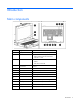
Introduction Main components Callout Component Function 1 Display release latch Pushes down to unlatch the display assembly 2 Blue LED • • Turns on when the display is closed Helps identify the HP TFT7600 KVM Console in a rack 3 OSD activation button • • • Launches OSD menus Selects Exits menus and OSD 4 OSD scroll up and down button Used to scroll in the OSD menu and adjust functions 5 Scroll lock LED Lights when Scroll lock is on 6 Cap lock LED Lights when Cap lock is on 7 Number
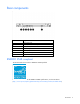
Rear components Callout Component 1 USB pass-through 2 USB keyboard and mouse port 3 PS2 keyboard port 4 PS2 mouse port 5 VGA input port 6 Power connection port 7 Serial firmware port ENERGY STAR compliant The HP TFT7600 KVM Console is ENERGY STAR® qualified. For more information about the ENERGY STAR® qualifications, see the HP website (http://www.hp.com/hpinfo/globalcitizenship/environment/products/ecolabels.html).
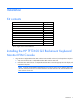
Installation Kit contents Item Quantity HP TFT7600 KVM Console 1 M6 screws 4 6-32 screws 5 HP Adjustable Toolless Rails 2 Cable management arm, power adapter with brace rail 1 Lock plates 2 USB cables 2 PS2 cables 2 Video cable 1 Power cords 2 USB cable labels 2 This kit might contain extra hardware. Installing the HP TFT7600 G2 Rackmount Keyboard Monitor KVM Console 1. Align the HP 1U Adjustable Toolless Rails with the holes marked on the rack, and snap them into place. a.
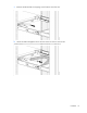
2. Extend the inner slides until they lock into place. 3. Align the unit with the extended inner slides, and then insert the unit into the rack.
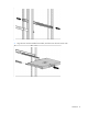
4. From the rear of the rack, slide the brace rail assembly in between the HP 1U Adjustable Toolless Rails. 5. Align the screw holes on the brace rail with the screw holes on the HP 1U Adjustable Toolless Rails. 6. Using two 6-32 screws, secure the brace rail to the HP 1U Adjustable Toolless Rails.
7. Remove and discard the two shipping screws from the rear of the unit. 8. Attach the cable management arm to the rear of the unit with two 6-32 screws.
9. Connect and route the cables through the cable management arm and unit opening. Installation is complete. Connecting and routing cables When connecting and routing the cables through the cable management arm and cable tray to the HP TFT7600 KVM Console, use the following cable-routing method to ensure that the cables fit into the tray. IMPORTANT: Use either the PS/2 cables or USB keyboard/mouse cable when connecting the unit to a device. Do not use both.
The following figure illustrates where the cables connect and how to route the cables in the tray. Item Description 1 Power cable 2 VGA cable 3 USB keyboard/mouse cable 4 USB pass-through cable Accessing the HP TFT7600 KVM Console 1. Gently extend the HP TFT7600 KVM Console until the slides lock. 2. Push the display release latch, and then lift the display.
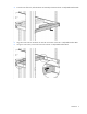
Removing the HP 1U Adjustable Toolless Rails 1. Locate the spring release. 2. Place your hand on the outside of the HP 1U Adjustable Toolless Rails so that you can move the spring release. 3. Gently move the spring release toward the inside of the rack (1) while moving the HP 1U Adjustable Toolless Rails out toward you and away from the rack (2).
2. Slide it back to release the locking mechanism and gently pull to remove the cable. Enabling the native display resolution of 1440x900 in HP-UX To fix issues related to wide screen panels, verify that you have at least one of the following server patches (or newer) installed: • PHSS_40809 (11.31) • PHSS_40810 (11.23) For more information about setting resolutions in HP-UX, see the Graphics Administration Guide for HP-UX 11.x servers on the HP website (http://docs.hp.com/en/5900-0585/5900-0585.
Operational overview On-screen display The OSD buttons are used to operate the HP TFT7600 KVM Console OSD menus. Callout Component Function 1 OSD activation button • • • 2 OSD scroll up and down button Used to scroll in the OSD menu and adjust the function Launches OSD menus Selects menu options Exits menus and OSD Launching OSD menu To launch the OSD menu: 1. Press the OSD activation button on the front panel. The main menu displays on the screen. 2.
• Use the OSD activation button to select a sub-menu or a function. Example: To exit the OSD menu: 1. Press the Down (-) button to scroll to the Exit function. 2. Press the OSD activation button to select the Exit function and exit the OSD menu. OSD menu The OSD menu provides access to display settings and functions, enabling the user to customize the HP TFT7600 KVM Console display settings.
Vertical position The V position option displays a slider bar to enable the adjustment of the screen's vertical position. The center of the bar is obtained from the factory-preset value for Vertical Position. Clock The Clock option displays a slider bar to enable the adjustment of the Horizontal Clocks. Phase The Phase option displays a slider bar to enable the adjustment of the analog signals phase.
Auto Configuration The Auto Configuration option performs four functions automatically: • Auto Level—Automatically adjusts the black and white levels of the screen • Auto Position—Automatically adjusts the position of the screen • Auto Phase—Automatically adjusts the phase • Auto Clock—Automatically adjusts the output clock per line to match the input Factory settings The Factory settings option enables the user to set the HP TFT7600 back to its original factory settings.
Maintenance Maintenance guidelines To protect your unit from overheating and other types of damage: • Use only a power source and connection appropriate for this unit, as indicated on the marking label and back plate. • If an extension cord or power strip is used, be sure that the cord or strip is rated for the product. Also, be sure that the total ampere ratings of all products plugged into the extension cord or power strip do not exceed 80% of the extension cord or power strip ampere ratings limit.
Shipping instructions Keep the original packing box in a storage area in case you must move or ship your HP TFT7600 KVM Console. Moving a rack with the HP TFT7600 KVM Console installed When moving the HP TFT7600 KVM Console installed in a rack, HP recommends that you install the lock plates, included in your kit, on each side of the unit and rack. To install lock plates: 1. Place the lock plate into the slot and rotate it back. 2.
Regulatory compliance notices Regulatory compliance identification numbers For the purpose of regulatory compliance certifications and identification, this product has been assigned a unique regulatory model number. The regulatory model number can be found on the product nameplate label, along with all required approval markings and information. When requesting compliance information for this product, always refer to this regulatory model number.
radio communications. However, there is no guarantee that interference will not occur in a particular installation. If this equipment does cause harmful interference to radio or television reception, which can be determined by turning the equipment off and on, the user is encouraged to try to correct the interference by one or more of the following measures: • Reorient or relocate the receiving antenna. • Increase the separation between the equipment and receiver.
This Class A digital apparatus meets all requirements of the Canadian Interference-Causing Equipment Regulations. Cet appareil numérique de la classe A respecte toutes les exigences du Règlement sur le matériel brouilleur du Canada. Class B equipment This Class B digital apparatus meets all requirements of the Canadian Interference-Causing Equipment Regulations. Cet appareil numérique de la classe B respecte toutes les exigences du Règlement sur le matériel brouilleur du Canada.
Japanese notice BSMI notice Korean notice Class A equipment Class B equipment Regulatory compliance notices 24
Chinese notice Class A equipment China energy regulations Disposal of waste equipment by users in private households in the European Union This symbol on the product or on its packaging indicates that this product must not be disposed of with your other household waste. Instead, it is your responsibility to dispose of your waste equipment by handing it over to a designated collection point for the recycling of waste electrical and electronic equipment.
Power cord statement for Japan Regulatory compliance notices 26
Electrostatic discharge Preventing electrostatic discharge To prevent damaging the system, be aware of the precautions you need to follow when setting up the system or handling parts. A discharge of static electricity from a finger or other conductor may damage system boards or other static-sensitive devices. This type of damage may reduce the life expectancy of the device. To prevent electrostatic damage: • Avoid hand contact by transporting and storing products in static-safe containers.
Support and other resources HP contact information For United States and worldwide contact information, see the Contact HP website (http://www.hp.com/go/assistance). In the United States: • To contact HP by phone, call 1-800-334-5144. For continuous quality improvement, calls may be recorded or monitored. • If you have purchased a Care Pack (service upgrade), see the Support & Drivers website (http://www8.hp.com/us/en/support-drivers.html).
Acronyms and abbreviations KVM keyboard, video, and mouse OSD on-screen display RKM rackmount keyboard monitor TFT thin film transistor USB universal serial bus Acronyms and abbreviations 29
Documentation feedback HP is committed to providing documentation that meets your needs. To help us improve the documentation, send any errors, suggestions, or comments to Documentation Feedback (mailto:docsfeedback@hp.com). Include the document title and part number, version number, or the URL when submitting your feedback.
Index A I accessing the unit 12 Advanced 17 authorized reseller 28 auto-configuration process 18 Image Enhancement 16 installation instructions 7 installation overview 7 introduction 5 B J BSMI notice 24 Japanese notice 24 C K cable connectors 13 cables, connecting and routing 11 Canadian notice 22 Clock Adjust 17 components 5, 6 kit contents 7 Korean notices 24 D Declaration of Conformity 22 default 17 E electrostatic discharge 27 Energy Star 6 European Union regulatory notice 23 F factory de
R rear components 6 regulatory compliance notices 21, 25 Removing the Brace Rail Assembly 13 removing the HP 1U Adjustable Toolless Rails 13 removing the unit 13 S shipping the unit 20 T technical support 28 telephone numbers 28 V Vertical Position 17 W website, HP 28 Index 32