HP UPS R/T3000 User Guide Part Number 507932-002 December 2009 (Second Edition)
© Copyright 2009 Hewlett-Packard Development Company, L.P. The information contained herein is subject to change without notice. The only warranties for HP products and services are set forth in the express warranty statements accompanying such products and services. Nothing herein should be construed as constituting an additional warranty. HP shall not be liable for technical or editorial errors or omissions contained herein. Microsoft, Windows, and Windows Server are U.S.
Contents Component identification ............................................................................................................... 7 UPS R/T3000 overview ................................................................................................................................ 7 UPS front panel ............................................................................................................................................ 7 UPS front panel controls ............................
Attaching the ERM front bezel ........................................................................................................... 35 Attaching the tower conversion stands ................................................................................................ 35 Continuing the installation ................................................................................................................. 37 UPS operations ........................................................................
UPS does not provide the expected backup time ........................................................................................... 57 UPS frequently switches between utility and battery power ............................................................................. 58 Specifications ............................................................................................................................. 59 UPS physical specifications ...........................................................
Grounding methods to prevent electrostatic discharge .................................................................................... 74 Acronyms and abbreviations ........................................................................................................ 75 Index .........................................................................................................................................
Component identification UPS R/T3000 overview The HP UPS R/T3000 features a 2U rack-mount with convertible tower design and offers power protection for loads up to a maximum of 3300 VA/3000 W (these numbers might vary by model). To benefit from the latest product enhancements, update to the latest versions of UPS firmware and software. NOTE: To download the latest versions of UPS firmware and software, see the HP website (http://www.hp.com/go/rackandpower).
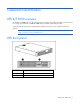
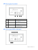
UPS front panel controls Item Description Function 1 Test/Alarm Reset button Silences UPS alarms ("Silencing an audible alarm" on page 42) 2 Off button Places the UPS in Standby mode (on page 38) 3 On button Powers up the UPS ("Starting power to the load" on page 26) 4 Battery Start button Starts the UPS on battery power when pressed with the On button UPS front panel LED indicators Component identification 8
The front panel is shown with the bezel removed. Item LED description Load level 1 Self Test On—The load level is greater than 10%. 2 Battery Fault On—The load level is greater than 25%. 3 Site Wiring Fault On—The load level is greater than 50%. 4 Overtemperature On—The load level is greater than 75%. 5 Overload On—The load level is greater than 100%. 6 On Bypass 7 On Battery 8 Utility For more information, see "LED troubleshooting (on page 52)" .
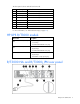
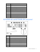
Item Description 1 REPO port 2 Ground bonding screw 3 USB communications port 4 Serial communications port 5 Load segment 1 (two NEMA 5-20T receptacles) 6 Load segment 2 (two NEMA 5-20T receptacles) 7 PDU output (NEMA L5-30R) receptacle (load segment 1) 8 ERM connector 9 Cord retention clip attachment locations 10 Load segment circuit breakers 11 Power cord with L5-30 plug 12 Option slot R/T3000h NA and R/T3000h JPN rear panel Item Description 1 Option slot 2 USB port 3 Ser
Item Description 10 Cord retention clip attachment locations 11 Ground bonding screw 12 REPO port 13 Power cord with L6-20 plug R/T3000 INT rear panel Item Description 1 Option slot 2 USB port 3 Serial communications port 4 Load segment 1 (one IEC-320-C19 receptacle) 5 Load segment 2 (one IEC-320-C19 receptacle) 6 Load segment 1 (three IEC-320-C13 receptacles) 7 Load segment 2 (three IEC-320-C13 receptacles) 8 ERM connector 9 Cord retention clip attachment locations 10 Ground
must be connected to a remote, normally-open switch (not supplied). The REPO switch is used in conjunction with a main disconnect device that removes the AC source from the input of the UPS. When the switch is closed: • The REPO feature immediately powers down protected devices and does not utilize the orderly shutdown procedure initiated by power management software. • The REPO feature shuts down UPS units operating under either utility or battery power.
Installation Precautions Save these instructions. This document contains important safety instructions that should be followed during installation, operation, and maintenance of the UPS and batteries. WARNING: A risk of personal injury from electric shock and hazardous energy levels exists. The installation of options and routine maintenance and service of this product must be performed by individuals who are knowledgeable about the procedures, precautions, and hazards associated with AC power products.
• Hex nuts • Cage nuts • Cage nut-fitting tool Selecting a site WARNING: To prevent fire or electric shock, install the unit in a temperature- and humiditycontrolled indoor environment, free of conductive contaminants. When selecting a site, consider the following factors: • Elevated operating ambient temperature—If the equipment is installed in a closed or multi-unit rack assembly, the operating ambient temperature of the rack environment might be greater than room ambient temperature.
WARNING: To reduce the risk of personal injury or damage to the equipment, be sure that: • The leveling feet are extended to the floor. • The full weight of the rack rests on the leveling feet. • The stabilizing feet are attached to the rack if it is a single-rack installation. • The racks are coupled together in multiple-rack installations. • Only one component is extended at a time. A rack may become unstable if more than one component is extended for any reason.
2. Insert screws through the rack into the mounting rail and the front of each mounting bracket. 3. Install cage nuts or clip nuts into the rear of the rack.
4. Insert screws through the mounting rail into the cage nuts or clip nuts. 5. Tighten the wing nuts or hex nuts.
6. Install the rear stabilization bracket using wing nuts. Wait until the unit is installed and the brackets are adjusted before tightening the nuts. Installing the UPS in a rack Before installing the unit, review and adhere to all warnings provided in "Precautions (on page 13)." WARNING: A risk of personal injury or damage to the equipment exists. Uneven loading of equipment in the rack might cause the rack to become unstable.
4. Attach the chassis to the rack using the supplied screws. Connecting the battery leads WARNING: To prevent personal injury from electric shock or damage to the equipment, remove the battery lead labels, and verify that the ERM circuit breakers are in the Off position.
Attaching the UPS front bezel Connecting the serial communications port CAUTION: Use only the computer interface cable supplied with the UPS to connect the communications port to the host computer. IMPORTANT: Power management software requires the communications port to be appropriately cabled to the host computer.
Connecting the USB communications port Connecting the REPO port Installation 21
WARNING: The pins on the REPO port are polarity sensitive. Be sure to verify polarity while connecting the REPO port. WARNING: To meet the requirements stated in NEC (NFPA 70) Articles 645-10 and 645-11, a UPS installed in a computer equipment room must be connected to a REPO circuit. IMPORTANT: The remote switch must be in the Off (open) position to enable power to the output receptacles. NOTE: Wire the connector block using stranded, nonshielded wire (AWG #22 - #18, or equivalent).
• Minimize wire strain while connecting the REPO port. • Avoid allowing the wires to hang in the rear of the UPS. • Use tie wraps and tie wrap blocks to secure the wires tightly to the rack and the rear of the UPS. For more information about the REPO port, see "REPO port (on page 11)" . For information about verifying the REPO connection, see "Verifying the REPO port connection (on page 42)" .
The ground bonding cable is not included. Connecting the UPS to utility power WARNING: To prevent injury from electric shock or damage to the equipment: • Plug the input line cord into a grounded (earthed) electrical outlet that is installed near the equipment and is easily accessible. • Do not disable the grounding plug on the input line cord. The grounding plug is an important safety feature. • Do not use extension cords. Connect the UPS to a grounded utility power outlet.
CAUTION: Do not plug laser printers into the UPS output receptacles. The instantaneous current drawn by this type of printer can overload the UPS. Before connecting devices, verify that the UPS will not overload by checking that the ratings of the devices do not exceed the UPS capacity. If the equipment rating is listed in amps, multiply the number of amps by the selected output voltage to determine the VA.
IMPORTANT: Charge the batteries for at least 24 hours before supplying backup power to devices. The batteries charge to: • 80 percent of their capacity within 3 hours • 100 percent of their capacity within 48 hours Starting power to the load Start power to the load by placing the UPS in Operate mode (on page 38). IMPORTANT: AC power must be available the first time the UPS is started.
Rotating the logo badge Gently pull out the logo badge, rotate it 90 degrees, and then replace it in the bezel. Attaching the UPS front bezel Attaching the tower conversion stands WARNING: To reduce the risk of personal injury or damage to the equipment, the tower conversion stands must be properly attached when the unit is installed as a tower.
Using the preinstalled screws, attach the tower conversion stands to the unit. Continuing the installation To continue the UPS installation, follow the instructions starting with "Connecting the serial communications port (on page 20).
Installing the extension bars (if included) Installation 29
Connecting and securing the power cords Installing the ERM in a rack Before installing the unit, review and adhere to all warnings provided in "Precautions (on page 13)." WARNING: A risk of personal injury or damage to the equipment exists. Uneven loading of equipment in the rack might cause the rack to become unstable. Install the heavier components first, and then continue to populate the rack from the bottom to the top. 1. Install the mounting rails ("Installing the mounting rails" on page 14). 2.
4. Attach the chassis to the rack using the supplied screws.
Attaching the ERM front bezel Installation 32
Connecting the ERM to the UPS 1. Remove the ERM connector bracket from the UPS. 2. Plug the ERM cable (2) in the socket (1) at the rear of the UPS.
3. Attach the ERM connector bracket to the UPS as a cord retention bracket for the ERM cable. 4. To install a second ERM: a. Remove the ERM connector bracket from the first ERM. b. Plug the cable from the second ERM into the socket at the rear of the first ERM. Up to two ERM units can be connected. c. Attach the ERM connector bracket to the first ERM as a cord retention bracket for the ERM cable.
Installing the ERM as a tower Before installing the unit, review and adhere to all warnings provided in "Precautions (on page 13)." The tower stands and associated hardware ship with the UPS. Rotating the logo badge Gently pull out the logo badge, rotate it 90 degrees, and then replace it in the bezel.
WARNING: To reduce the risk of personal injury or damage to the equipment, the tower conversion stands must be properly attached when the unit is installed as a tower. 1. Using the preinstalled screws, attach the tower conversion stands to the unit. 2. Remove a screw from the inner-most, rear corner of the UPS and ERM. 3. To attach the tower brackets: o For the front bracket, use the mounting ear screws.
o For the rear bracket, use the screws removed from the chassis. Continuing the installation To continue the ERM installation, follow the instructions starting with "Connecting the ERM to the UPS (on page 33).
UPS operations Modes of operation The UPS has five modes of operation: • Standby mode (on page 38) • Operate mode (on page 38) • Configure mode (on page 39) • Battery mode (on page 39) • Auto-Bypass mode (on page 39) Standby mode In Standby mode: • No power is available at the UPS output receptacles. • The UPS charges the batteries as necessary. The UPS can be placed in Standby mode when the UPS is in Operate mode (on page 38).
For the location of buttons, see "UPS front panel controls (on page 8)." For the location of LEDs, see "UPS front panel LED indicators (on page 8)." Configure mode The UPS can be placed in Configure mode while in Operate mode (on page 38), Battery mode (on page 39) or Standby mode (on page 38). In Configure mode: • Power is available at the UPS receptacles when entered from Operate mode. Power is not available at the receptacles when entered from Standby mode.
NOTE: If the On and Off buttons are simultaneously pressed, the Off button has priority over the On button. Button Assertion time Audible alarm Mode before assertion Utility present ? Action On 0.5 seconds Every 0.
In Configure mode, the LED front panel display changes function to enable modification of the UPS parameters. Each LED is associated with a different parameter.
For information on what to do if the self-test detects a problem, see "Troubleshooting (on page 52)." Silencing an audible alarm To silence an alarm, press the Test/Alarm Reset button ("UPS front panel controls" on page 8). IMPORTANT: • Although the audible alarm silences, the condition that caused the alarm to sound may still exist. • If a utility power failure caused the alarm, the alarm silences after power is restored.
Maintenance Removing the UPS front bezel Removing the ERM front bezel Replacing the UPS option card This component is hot-swappable and can be replaced without powering down the UPS.
1. (optional) To replace the component with the UPS powered down, refer to "Powering down the UPS (on page 42)." 2. Disconnect the communications cable from the option card. 3. Remove the two screws securing the option card and slide the card out. To replace the component, reverse the removal procedure. NOTE: Replacing the option card might require power management software to be restarted or reconfigured. Replacing the batteries To replace the batteries: 1.
WARNING: To prevent personal injury from hazardous energy: • Remove watches, rings, or other metal objects. • Use tools with insulated handles. • Do not place tools or metal parts on top of batteries. WARNING: To prevent personal injury, prepare the area and observe all materials-handling procedures when transporting a battery module. Battery modules weigh 20 kg (44.1 lb). NOTE: Replace all battery modules at the same time.
CAUTION: Because of the short shelf life of the batteries, avoid storing a battery spare as a backup. Do not maintain an inventory of spare batteries on site unless a procedure to keep these batteries charged while in storage is implemented. UPS battery replacement procedure WARNING: To prevent personal injury from electric shock or damage to the equipment, remove the battery lead labels, and verify that the ERM circuit breakers are in the Off position.
To replace the components, reverse the removal procedure. IMPORTANT: Charge the batteries for at least 24 hours before supplying backup power to devices. The batteries charge to: • 80 percent of their capacity within 3 hours • 100 percent of their capacity within 48 hours Testing the new battery module After installing the new battery module, press the Test/Alarm Reset button to initiate a self-test ("Initiating a self-test" on page 41).
2. Power down the UPS ("Powering down the UPS" on page 42). 3. Switch the circuit breaker for any attached ERMs to the Off position. 4. Unplug the UPS power cord. 5. Disconnect the communications cable from the option card. 6. Disconnect the ground bonding cable. 7. Disconnect the REPO port. 8. Unplug the load devices. 9. Unplug the ERM connected to the UPS. 10. Remove the UPS front bezel ("Removing the UPS front bezel" on page 43). 11. Disconnect the battery leads. 12.
1. Connect the USB to serial converter to the USB port on your system. 2. Click Start, select Control Panel, and then double-click System. The System Properties screen appears. 3. Click the Hardware tab. 4. Click Device Manager. The Device Manager screen appears. 5. In the tree displayed in the left panel, click the Ports (COM & LPT) branch to expand. 6. Double-click the port that is assigned to your USB to serial converter device.
1. From the open Device Manager screen, locate the USB device that is assigned to COM 1. 2. Double-click the port name. The Port Properties screen appears. 3. Click the Port Settings tab. The Port Settings screen appears. 4. Click Advanced. The Advanced Settings screen appears. 5. Select an available USB port number from the COM Port Number drop down menu. 6. Click OK to close the Advanced screen. 7. Click OK to close the Port Settings screen. 8.
Power management Power management software HP Power Manager software ensures maximum power reliability of computer systems through comprehensive control of UPSs. The easy-to-use browser interface enables novice users to configure and manage power protection settings. To download the latest version of HP Power Manager software, see the HP website (http://www.hp.com/go/rackandpower). NOTE: To install and configure the software, see the software user guide.
Troubleshooting LED troubleshooting Utility LED On Batter y LED On Bypas s LED Self Test LED Battery Fault LED Site Wiring Fault LED Over Temp LED Overloa d LED Condition On— Load <10% Off Off On— Load >10% On— Load >25% On— Load >50% On— Load >75% Off UPS is in Operate mode (on page 38) Flashin g Off Off Off * * * Off UPS is in Standby mode (on page 38) Off Off On On— Load >10% On— Load >25% On— Load >50% On— Load >75% Off UPS is in Auto-Bypass mode (on page 39) Flashin
Off On Off On— Battery capacity <25% On— Battery capacity >25% On— Battery capacity >50% On— Battery capacity >75% Off UPS is on battery (on page 55)—No utility power * * * Off * * Flashing * Overtemperature condition (on page 56) Off Off On Flashing Flashing Flashing Flashing Flashing Internal UPS fault condition (on page 56) Flashin g Off Off Flashing Flashing Flashing Flashing Flashing REPO condition (on page 56) * Off * Off * Flashing * * Site wiring condition
• Overload The load is supported, but not protected while in Auto-Bypass mode. Action: 1. If power management software is being used, check the log files to obtain specific error information to help identify the problem. For more information about the causes of a general fault condition, see the HP Power Manager user guide available for download from the HP website (http://www.hp.com/go/rackandpower). 2. Verify that no blockage of airflow to the front bezel and rear panel exists.
b. If the Battery Fault LED is red, replace the batteries ("UPS battery replacement procedure" on page 46). 3. Reduce the load: a. Power down the UPS ("Powering down the UPS" on page 42). b. Remove one or more load devices to reduce the power requirements. c. Wait at least 5 seconds and restart the UPS. d. If the condition persists, verify that the load devices are not defective. 4. Allow the UPS to cool: a. Power down the UPS ("Powering down the UPS" on page 42). b.
Input voltage is out of range Action: 1. Check the input voltage and reconfigure the UPS ("Configuring the UPS" on page 40). 2. Contact a qualified electrician to verify that the utility power is suitable for the UPS. Overtemperature condition Possible cause: The UPS internal temperature is too high, or a fan has failed. Action: 1. Power down the UPS ("Powering down the UPS" on page 42). 2. Allow the UPS to cool: a. Clear vents and remove any heat sources. b.
Overload condition All the load LEDs are illuminated. Action: 1. Power down the UPS ("Powering down the UPS" on page 42). 2. Remove one or more load devices to reduce the power requirements. 3. Wait at least 5 seconds and restart the UPS. 4. If the condition persists, verify that the load devices are not defective. Checksum failure error A Checksum failure error occurs when executing a bad load sequence, or having an incorrect EEPROM map while loading software through the serial or USB port.
5. During extended power outages, save your work, power down the load devices, and then power down the UPS ("Powering down the UPS" on page 42) to conserve battery power. UPS frequently switches between utility and battery power Action: 1. Check the input voltage and reconfigure the UPS ("Configuring the UPS" on page 40). 2. Contact a qualified electrician to verify that the utility power is suitable for the UPS.
Specifications UPS physical specifications Parameter Value Height 8.9 cm (3.5 in) Depth 63.5 cm (25 in) Width 44.5 cm (17.5 in) Weight 37 kg (82 lb) ERM physical specifications Parameter Value Height 8.9 cm (3.5 in) Depth 63.5 cm (25 in) Width 44.5 cm (17.
UPS model R/T3000h NA/JPN Load segment Output receptacles 2 2 x 5-20T 1 3 x IEC-320-C13 1 x IEC-320-C19 1 x L6-20R 2 3 x IEC-320-C13 1 x IEC-320-C19 R/T3000 INTL 1 3 x IEC-320-C13 1 x IEC-320-C19 2 3 x IEC-320-C13 1 x IEC-320-C19 Power protection specifications UPS model VA Nominal power rating (W) Nominal voltage setting R/T3000 NA/JPN 2880 2700 100, 110, 120, 127 R/T3000h NA/JPN 3300 3000 204, 220, 230, 240 R/T3000 INTL 3300 3000 204, 220, 230, 240 Output tolerance specificat
Battery specifications Feature Specification Type 12 V, 5 AH, sealed, maintenance-free, rechargeable, valve regulated lead-acid batteries with a 3-5 year service life at 25°C (77°F). Voltage The battery modules have a battery string voltage of 120 V. Charging Complete charge takes no more than 48 hours. After approximately 3 hours, the batteries reach 80% charge at default nominal utility voltage and no load.
REPO port specifications The REPO port meets the requirements of NFPA Articles 645-10 and 645-11 for a Disconnecting Means.
Spares Ordering spares To order a spare, visit the HP website (http://www.hp.com/buy/parts). To replace parts under warranty, contact an HP authorized service representative.
ERM spare parts list Item Description Spare part number 1 ERM unit 517702-001 * UPS/ERM mounting brackets 582931-001 * Mounting rails with screws 419181-001 * not shown Hardware options For information on the supported hardware options, see the HP website (http://www.hp.com/go/rackandpower).
Technical support Before you contact HP Be sure to have the following information available before you call HP: • Technical support registration number (if applicable) • Product serial number • Product model name and number • Product identification number • Applicable error messages • Add-on boards or hardware • Third-party hardware or software • Operating system type and revision level HP contact information For the name of the nearest HP authorized reseller: • See the Contact HP worldwi
Warranty information Limited warranty To back up the wide range of features offered with the UPS, a 3-year limited warranty is provided. $250,000 Computer Load Protection Guarantee In addition to the limited warranty, a $250,000 Computer Load Protection Guarantee (provided by the original equipment manufacturer) is offered. IMPORTANT: The $250,000 Computer Load Protection Guarantee is offered only in The United States and Canada.
Recommended duration of use Although tests and a multitude of customer experiences have shown no noticeable performance issues with UPSs for significant time periods after expiration of the 3-year limited warranty, we strongly recommend considering replacing UPSs after a maximum of 5 to 6 years of use to assure full functionality and a safe operating environment.
Regulatory compliance notices Regulatory compliance identification numbers For the purpose of regulatory compliance certifications and identification, this product has been assigned a unique regulatory model number. The regulatory model number can be found on the product nameplate label, along with all required approval markings and information. When requesting compliance information for this product, always refer to this regulatory model number.
to radio communications. However, there is no guarantee that interference will not occur in a particular installation. If this equipment does cause harmful interference to radio or television reception, which can be determined by turning the equipment off and on, the user is encouraged to try to correct the interference by one or more of the following measures: • Reorient or relocate the receiving antenna. • Increase the separation between the equipment and receiver.
Canadian notice (Avis Canadien) Class A equipment This Class A digital apparatus meets all requirements of the Canadian Interference-Causing Equipment Regulations. Cet appareil numérique de la classe A respecte toutes les exigences du Règlement sur le matériel brouilleur du Canada. Class B equipment This Class B digital apparatus meets all requirements of the Canadian Interference-Causing Equipment Regulations.
This symbol on the product or on its packaging indicates that this product must not be disposed of with your other household waste. Instead, it is your responsibility to dispose of your waste equipment by handing it over to a designated collection point for the recycling of waste electrical and electronic equipment.
BSMI notice Korean notice Class A equipment Class B equipment Chinese notice Class A equipment Battery replacement notice WARNING: Power products contain sealed lead-acid battery modules. A risk of fire and burns exists if the battery is not properly handled. To reduce the risk of personal injury: • Do not attempt to recharge the battery. • Do not expose the battery to temperatures higher than 60°C (140°F). • Do not disassemble, crush, puncture, short external contacts, or dispose of in fire or water.
Batteries, battery packs, and accumulators should not be disposed of together with the general household waste. To forward them to recycling or proper disposal, use the public collection system or return them to HP, an authorized HP Partner, or their agents. For more information about battery replacement or proper disposal, contact an authorized reseller or an authorized service provider.
Electrostatic discharge Preventing electrostatic discharge To prevent damaging the system, be aware of the precautions you need to follow when setting up the system or handling parts. A discharge of static electricity from a finger or other conductor may damage system boards or other static-sensitive devices. This type of damage may reduce the life expectancy of the device. To prevent electrostatic damage: • Avoid hand contact by transporting and storing products in static-safe containers.
Acronyms and abbreviations EEPROM electrical erasable programmable read only memory ERM extended runtime module IEC International Electrotechnical Commission LED light-emitting diode MOV metal oxide varistor NEC National Electrical Code NEMA National Electrical Manufacturers Association NFPA National Fire Protection Association PDU power distribution unit PFC power factor corrected REPO remote emergency power off THD total harmonic distortion Acronyms and abbreviations 75
UPS uninterruptible power system USB universal serial bus Acronyms and abbreviations 76
Index A alarm cannot be silenced 52 alarms, silencing 42 authorized reseller 65 Auto-Bypass mode 39, 53 B backup time, insufficient 57 batteries, care and storage 45 batteries, charging 25, 34 batteries, connecting 19, 31 batteries, obtaining 45 batteries, replacing 44, 45, 46 batteries, runtime 61 batteries, specifications 61 batteries, testing 47 battery bracket 46 battery cables, connecting 19, 31 battery condition 55 Battery Fault LED, location 8 Battery Fault LED, troubleshooting 52 Battery mode 39 ba
front front front front panel buttons 8 panel components 7, 8 panel LEDs 8 panel, 39 M maintenance 43 modes of operation 38, 54 modifications, FCC notice 69 mounting rails 14 G general alarm condition 54 ground bonding cable, connecting 23 grounding methods 74 N H O hardware options 64 hardware, preparing to install high-current output receptacle, high-current output receptacle, high-current output receptacle, HP Power Manager 51 HP technical support 65 obtaining new batteries 45 On Battery LED, loc
R/T3000 INTL 11 R/T3000 models 9 R/T3000 NA 9 R/T3000h JPN 10 R/T3000h NA 10 R/T3000j JPN 9 rack-to-tower conversion 26, 35 rails, installing 14 rear panel connectors 9, 10, 11, 12 recommended duration of use 67 regulatory compliance identification numbers 68 regulatory compliance notices 68, 70, 73 replacing the batteries 44, 46 replacing the ERM 48 replacing the option card 43 replacing the UPS 47 REPO condition 56 REPO port, connecting 21 REPO port, location 9, 10, 11 REPO port, overview 11 REPO port, sp