
HSG80 ACS Solution Software Version 8.7 for Compaq Tru64 UNIX Installation and Configuration Guide

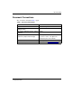
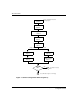
Table Of Contents
- HSG80 ACS Solution Software Version 8.7 for Compaq Tru64 UNIX Installation and Configuration Guide
- About this Guide
- 1- Planning a Subsystem
- Defining Subsystems
- What is Failover Mode?
- Selecting a Cache Mode
- Enabling Mirrored Caching
- What is the Command Console LUN?
- Determining Connections
- Assigning Unit Numbers
- What is Selective Storage Presentation?
- 2- Planning Storage Configurations
- Where to Start
- Determining Storage Requirements
- Configuration Rules for the Controller
- Addressing Conventions for Device PTL
- Choosing a Container Type
- Creating a Storageset Profile
- Planning Considerations for Storageset
- Changing Characteristics through Switches
- Specifying Storageset and Partition Switches
- Specifying Initialization Switches
- Specifying Unit Switches
- Creating Storage Maps
- 3- Preparing the Host System
- Installing RAID Array Storage System
- Making a Physical Connection
- Preparing LUNs for Access by Tru64 UNIX FileSystem
- DECsafe Available Server Environment (ASE)
- HSG80 Units and Tru64 UNIX Utilities
- Solution Software Upgrade Procedures
- New Features, ACS 8.7 for Tru64
- 4- Installing and Configuring HSG Agent
- 5- FC Configuration Procedures
- Establishing a Local Connection
- Setting Up a Single Controller
- Setting Up a Controller Pair
- Configuring Devices
- Configuring Storage Containers
- Assigning Unit Numbers and Unit Qualifiers
- Configuration Options
- Verifying Storage Configuration from Host
- 6- Using CLI for Configuration
- 7- Backing Up, Cloning, and Moving Data
- A- Subsystem Profile Templates
- Storageset Profile
- Storage Map Template 1 for the BA370 Enclosure
- Storage Map Template 2 for the second BA370 Enclosure
- Storage Map Template 3 for the third BA370 Enclosure
- Storage Map Template 4 for the Model 4214R Disk Enclosure
- Storage Map Template 5 for the Model 4254 Disk Enclosure
- Storage Map Template 6 for the Model 4310R Disk Enclosure
- Storage Map Template 7 for the Model 4350R Disk Enclosure
- Storage Map Template 8 for the Model 4314R Disk Enclosure
- Storage Map Template 9 for the Model 4354R Disk Enclosure
- B- Installing, Configuring, and Removing the Client
- C- SWCC Agent in TruCluster Environment
- SWCC Overview
- Running the SWCC Agent on a V4.0G Cluster
- Running the SWCC Agent under ASE Services
- Running the SWCC Agent on a V5.x Cluster
- Problems with Running the Agent on Multiple Clusters
- Configure the Controller
- Use Multiple-Bus Failover Mode
- Verify That the HSG80/HSG60 Unit Offsets Are Zero
- Install and Run the Agent on One Cluster Member
- Example of Installing the Agent on a Cluster Member
- Create the CAA Action Script
- Create the CAA Resource
- Glossary
- Index

Contents
xiHSG80 ACS Solution Software Version 8.7 for Compaq Tru64 UNIX Installation and
Configuration Guide
Figures
1 General configuration flowchart (panel 1) . . . . . . . . . . . . . . . . . . . . . . . . . . . . . xx
2 General configuration flowchart (panel 2) . . . . . . . . . . . . . . . . . . . . . . . . . . . . xxi
3 Configuring storage with SWCC . . . . . . . . . . . . . . . . . . . . . . . . . . . . . . . . . . . xxii
1–1 Location of controllers and cache modules in a Model 2200 enclosure. . . . . . 1–2
1–2 Location of controllers and cache modules in a BA370 enclosure. . . . . . . . . . 1–3
1–3 “This controller” and “other controller” for the Model 2200 enclosure. . . . . . 1–4
1–4 “This controller” and “other controller” for the BA370 enclosure. . . . . . . . . . 1–4
1–5 Transparent failover—normal operation. . . . . . . . . . . . . . . . . . . . . . . . . . . . . . 1–6
1–6 Transparent failover—after failover from controller B to controller A . . . . . . 1–7
1–7 Typical multiple-bus configuration. . . . . . . . . . . . . . . . . . . . . . . . . . . . . . . . . . 1–9
1–8 Mirrored caching. . . . . . . . . . . . . . . . . . . . . . . . . . . . . . . . . . . . . . . . . . . . . . . 1–11
1–9 Connections in separate-link, transparent failover mode configurations . . . . 1–14
1–10 Connections in single-link, transparent failover mode configurations . . . . . . 1–15
1–11 Connections in multiple-bus failover mode . . . . . . . . . . . . . . . . . . . . . . . . . . 1–16
1–12 LUN presentation to hosts, as determined by offset. . . . . . . . . . . . . . . . . . . . 1–18
1–13 Limiting host access in transparent failover mode . . . . . . . . . . . . . . . . . . . . . 1–22
1–14 Limiting host access in multiple-bus failover mode. . . . . . . . . . . . . . . . . . . . 1–25
1–15 Placement of the worldwide name label on the Model 2200 enclosure . . . . . 1–28
1–16 Placement of the worldwide name label on the BA370 enclosure . . . . . . . . . 1–29
2–1 Mapping a unit to physical disk drives . . . . . . . . . . . . . . . . . . . . . . . . . . . . . . . 2–4
2–2 PTL naming convention . . . . . . . . . . . . . . . . . . . . . . . . . . . . . . . . . . . . . . . . . . 2–5
2–3 How data is laid out on disks in BA370 enclosure configuration. . . . . . . . . . . 2–6
2–4 Storage container types . . . . . . . . . . . . . . . . . . . . . . . . . . . . . . . . . . . . . . . . . . 2–14
2–5 3-member RAID 0 stripeset (example 1) . . . . . . . . . . . . . . . . . . . . . . . . . . . . 2–18
2–6 3-member RAID 0 stripeset (example 2) . . . . . . . . . . . . . . . . . . . . . . . . . . . . 2–19
2–7 Mirrorsets maintain two copies of the same data . . . . . . . . . . . . . . . . . . . . . . 2–21
2–8 Mirrorset example 2 . . . . . . . . . . . . . . . . . . . . . . . . . . . . . . . . . . . . . . . . . . . . 2–21
2–9 5-member RAIDset using parity. . . . . . . . . . . . . . . . . . . . . . . . . . . . . . . . . . . 2–23
2–10 Striped mirrorset (example 1) . . . . . . . . . . . . . . . . . . . . . . . . . . . . . . . . . . . . . 2–25
2–11 Striped mirrorset (example 2) . . . . . . . . . . . . . . . . . . . . . . . . . . . . . . . . . . . . . 2–25
2–12 One example of a partitioned single-disk unit . . . . . . . . . . . . . . . . . . . . . . . . 2–26
2–13 Large chunk size increases request rate . . . . . . . . . . . . . . . . . . . . . . . . . . . . . 2–31
3–1 Dual-Bus Enterprise Storage RAID Array Storage System . . . . . . . . . . . . . . . 3–4
3–2 Single-Bus Enterprise Storage RAID Array Storage System. . . . . . . . . . . . . . 3–5