
HSG80 ACS Solution Software Version 8.7 for Compaq Tru64 UNIX Installation and Configuration Guide
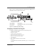
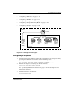
Table Of Contents
- HSG80 ACS Solution Software Version 8.7 for Compaq Tru64 UNIX Installation and Configuration Guide
- About this Guide
- 1- Planning a Subsystem
- Defining Subsystems
- What is Failover Mode?
- Selecting a Cache Mode
- Enabling Mirrored Caching
- What is the Command Console LUN?
- Determining Connections
- Assigning Unit Numbers
- What is Selective Storage Presentation?
- 2- Planning Storage Configurations
- Where to Start
- Determining Storage Requirements
- Configuration Rules for the Controller
- Addressing Conventions for Device PTL
- Choosing a Container Type
- Creating a Storageset Profile
- Planning Considerations for Storageset
- Changing Characteristics through Switches
- Specifying Storageset and Partition Switches
- Specifying Initialization Switches
- Specifying Unit Switches
- Creating Storage Maps
- 3- Preparing the Host System
- Installing RAID Array Storage System
- Making a Physical Connection
- Preparing LUNs for Access by Tru64 UNIX FileSystem
- DECsafe Available Server Environment (ASE)
- HSG80 Units and Tru64 UNIX Utilities
- Solution Software Upgrade Procedures
- New Features, ACS 8.7 for Tru64
- 4- Installing and Configuring HSG Agent
- 5- FC Configuration Procedures
- Establishing a Local Connection
- Setting Up a Single Controller
- Setting Up a Controller Pair
- Configuring Devices
- Configuring Storage Containers
- Assigning Unit Numbers and Unit Qualifiers
- Configuration Options
- Verifying Storage Configuration from Host
- 6- Using CLI for Configuration
- 7- Backing Up, Cloning, and Moving Data
- A- Subsystem Profile Templates
- Storageset Profile
- Storage Map Template 1 for the BA370 Enclosure
- Storage Map Template 2 for the second BA370 Enclosure
- Storage Map Template 3 for the third BA370 Enclosure
- Storage Map Template 4 for the Model 4214R Disk Enclosure
- Storage Map Template 5 for the Model 4254 Disk Enclosure
- Storage Map Template 6 for the Model 4310R Disk Enclosure
- Storage Map Template 7 for the Model 4350R Disk Enclosure
- Storage Map Template 8 for the Model 4314R Disk Enclosure
- Storage Map Template 9 for the Model 4354R Disk Enclosure
- B- Installing, Configuring, and Removing the Client
- C- SWCC Agent in TruCluster Environment
- SWCC Overview
- Running the SWCC Agent on a V4.0G Cluster
- Running the SWCC Agent under ASE Services
- Running the SWCC Agent on a V5.x Cluster
- Problems with Running the Agent on Multiple Clusters
- Configure the Controller
- Use Multiple-Bus Failover Mode
- Verify That the HSG80/HSG60 Unit Offsets Are Zero
- Install and Run the Agent on One Cluster Member
- Example of Installing the Agent on a Cluster Member
- Create the CAA Action Script
- Create the CAA Resource
- Glossary
- Index

FC Configuration Procedures
5–15HSG80 ACS Solution Software Version 8.7 for Compaq Tru64 UNIX Installation and
Configuration Guide
5–15
13. Turn on the switches if not done previously.
If you want to communicate with the FC switches through Telnet, set an IP
address for each switch. See the manuals that came with the switches for details.
Plug in the FC Cable and Verify Connections
14. Plug the FC cable from the first host adapter into the switch. Enter a SHOW
CONNECTIONS
command to view the connection table:
SHOW CONNECTIONS
The first connection will have one or more entries in the connection table. Each
connection will have a default name of the form !NEWCONxx, where xx is a
number representing the order in which the connection was added to the
connection table.
For a description of why plugging in one adapter can result in multiple
connections, see “Numbers of Connections,” page 1–13.
15. Rename the connections to something meaningful to the system and easy to
remember. For example, to assign the name ANGEL1A1 to connection
!NEWCON01, enter:
RENAME !NEWCON01 ANGEL1A1
StorageWorks recommends using a naming convention, see “Naming
Connections,” page 1–13.
16. Specify the operating system for the connection:
SET ANGEL1A1 OPERATING_SYSTEM=TRU64_UNIXAIX_CAMBEX
17. Verify the changes:
SHOW CONNECTIONS
Mark or tag all Fibre Channel cables at both ends for ease of maintenance.
Repeat Procedure for Each Host Adapter Connection
18. Repeat steps 15, 16, and 17 for each of that adapter’s host connections or delete
the unwanted connections from the table.
19. For each host adapter, repeat steps 14 through 18.