
HSG80 ACS Solution Software Version 8.7 for Compaq Tru64 UNIX Installation and Configuration Guide
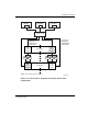
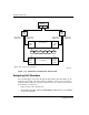

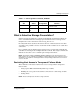

Table Of Contents
- HSG80 ACS Solution Software Version 8.7 for Compaq Tru64 UNIX Installation and Configuration Guide
- About this Guide
- 1- Planning a Subsystem
- Defining Subsystems
- What is Failover Mode?
- Selecting a Cache Mode
- Enabling Mirrored Caching
- What is the Command Console LUN?
- Determining Connections
- Assigning Unit Numbers
- What is Selective Storage Presentation?
- 2- Planning Storage Configurations
- Where to Start
- Determining Storage Requirements
- Configuration Rules for the Controller
- Addressing Conventions for Device PTL
- Choosing a Container Type
- Creating a Storageset Profile
- Planning Considerations for Storageset
- Changing Characteristics through Switches
- Specifying Storageset and Partition Switches
- Specifying Initialization Switches
- Specifying Unit Switches
- Creating Storage Maps
- 3- Preparing the Host System
- Installing RAID Array Storage System
- Making a Physical Connection
- Preparing LUNs for Access by Tru64 UNIX FileSystem
- DECsafe Available Server Environment (ASE)
- HSG80 Units and Tru64 UNIX Utilities
- Solution Software Upgrade Procedures
- New Features, ACS 8.7 for Tru64
- 4- Installing and Configuring HSG Agent
- 5- FC Configuration Procedures
- Establishing a Local Connection
- Setting Up a Single Controller
- Setting Up a Controller Pair
- Configuring Devices
- Configuring Storage Containers
- Assigning Unit Numbers and Unit Qualifiers
- Configuration Options
- Verifying Storage Configuration from Host
- 6- Using CLI for Configuration
- 7- Backing Up, Cloning, and Moving Data
- A- Subsystem Profile Templates
- Storageset Profile
- Storage Map Template 1 for the BA370 Enclosure
- Storage Map Template 2 for the second BA370 Enclosure
- Storage Map Template 3 for the third BA370 Enclosure
- Storage Map Template 4 for the Model 4214R Disk Enclosure
- Storage Map Template 5 for the Model 4254 Disk Enclosure
- Storage Map Template 6 for the Model 4310R Disk Enclosure
- Storage Map Template 7 for the Model 4350R Disk Enclosure
- Storage Map Template 8 for the Model 4314R Disk Enclosure
- Storage Map Template 9 for the Model 4354R Disk Enclosure
- B- Installing, Configuring, and Removing the Client
- C- SWCC Agent in TruCluster Environment
- SWCC Overview
- Running the SWCC Agent on a V4.0G Cluster
- Running the SWCC Agent under ASE Services
- Running the SWCC Agent on a V5.x Cluster
- Problems with Running the Agent on Multiple Clusters
- Configure the Controller
- Use Multiple-Bus Failover Mode
- Verify That the HSG80/HSG60 Unit Offsets Are Zero
- Install and Run the Agent on One Cluster Member
- Example of Installing the Agent on a Cluster Member
- Create the CAA Action Script
- Create the CAA Resource
- Glossary
- Index

Planning a Subsystem
1–21HSG80 ACS Solution Software Version 8.7 for Compaq Tru64 UNIX Installation and
Configuration Guide
1–21
What is Selective Storage Presentation?
Selective Storage presentation is a feature of the HSG80 controller that enables the
user to control the allocation of storage space and shared access to storage across
multiple hosts. This is also known as Restricting Host Access.
In a subsystem that is attached to more than one host or if the hosts have more than
one adapter, it is possible to reserve certain units for the exclusive use of certain host
connections.
For a controller pair, the method used to restrict host access depends on whether the
controllers are in transparent or multiple-bus failover mode. For a single controller, the
methods are the same as for a controller pair in transparent failover.
NOTE: The default condition is ENABLE_ACCESS_PATH=ALL. This specifies that access
paths to ALL hosts are enabled. StorageWorks recommends that the user restrict host access
and that the access path be carefully specified to avoid providing undesired host connections
access to the unit.
Restricting Host Access in Transparent Failover Mode
Three methods can be used to restrict host access to storage units in transparent
failover mode:
• Using separate Fibre Channel links (either loop or fabric)
• Enabling the access path of selected host connections on a shared loop or fabric
• Setting offsets
NOTE: These techniques also work for a single controller.
Table 1–1: Unit Assignments and SCSI_VERSION
SCSI_VERSI
ON
Offset
Unit
Assignment
What the connection sees
LUN 0 as
SCSI-2 Divisible by
10
At offsets Unit whose number
matches offset
SCSI-3 Divisible by
10
Not at offsets CCL