
HSG80 ACS Solution Software Version 8.7 for Compaq Tru64 UNIX Installation and Configuration Guide
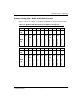
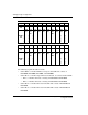

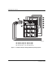
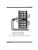
Table Of Contents
- HSG80 ACS Solution Software Version 8.7 for Compaq Tru64 UNIX Installation and Configuration Guide
- About this Guide
- 1- Planning a Subsystem
- Defining Subsystems
- What is Failover Mode?
- Selecting a Cache Mode
- Enabling Mirrored Caching
- What is the Command Console LUN?
- Determining Connections
- Assigning Unit Numbers
- What is Selective Storage Presentation?
- 2- Planning Storage Configurations
- Where to Start
- Determining Storage Requirements
- Configuration Rules for the Controller
- Addressing Conventions for Device PTL
- Choosing a Container Type
- Creating a Storageset Profile
- Planning Considerations for Storageset
- Changing Characteristics through Switches
- Specifying Storageset and Partition Switches
- Specifying Initialization Switches
- Specifying Unit Switches
- Creating Storage Maps
- 3- Preparing the Host System
- Installing RAID Array Storage System
- Making a Physical Connection
- Preparing LUNs for Access by Tru64 UNIX FileSystem
- DECsafe Available Server Environment (ASE)
- HSG80 Units and Tru64 UNIX Utilities
- Solution Software Upgrade Procedures
- New Features, ACS 8.7 for Tru64
- 4- Installing and Configuring HSG Agent
- 5- FC Configuration Procedures
- Establishing a Local Connection
- Setting Up a Single Controller
- Setting Up a Controller Pair
- Configuring Devices
- Configuring Storage Containers
- Assigning Unit Numbers and Unit Qualifiers
- Configuration Options
- Verifying Storage Configuration from Host
- 6- Using CLI for Configuration
- 7- Backing Up, Cloning, and Moving Data
- A- Subsystem Profile Templates
- Storageset Profile
- Storage Map Template 1 for the BA370 Enclosure
- Storage Map Template 2 for the second BA370 Enclosure
- Storage Map Template 3 for the third BA370 Enclosure
- Storage Map Template 4 for the Model 4214R Disk Enclosure
- Storage Map Template 5 for the Model 4254 Disk Enclosure
- Storage Map Template 6 for the Model 4310R Disk Enclosure
- Storage Map Template 7 for the Model 4350R Disk Enclosure
- Storage Map Template 8 for the Model 4314R Disk Enclosure
- Storage Map Template 9 for the Model 4354R Disk Enclosure
- B- Installing, Configuring, and Removing the Client
- C- SWCC Agent in TruCluster Environment
- SWCC Overview
- Running the SWCC Agent on a V4.0G Cluster
- Running the SWCC Agent under ASE Services
- Running the SWCC Agent on a V5.x Cluster
- Problems with Running the Agent on Multiple Clusters
- Configure the Controller
- Use Multiple-Bus Failover Mode
- Verify That the HSG80/HSG60 Unit Offsets Are Zero
- Install and Run the Agent on One Cluster Member
- Example of Installing the Agent on a Cluster Member
- Create the CAA Action Script
- Create the CAA Resource
- Glossary
- Index

Preparing the Host System
3–2 HSG80 ACS Solution Software Version 8.7 for Compaq Tru64 UNIX Installation and
Configuration Guide
CAUTION: Controller and disk enclosures have no power switches. Make sure the
controller enclosures and disk enclosures are physically configured before turning the
PDU on and connecting the power cords. Failure to do so can cause equipment
damage.
1. Be sure the enclosures are empty before mounting them into the rack. If necessary,
remove the following elements from the controller enclosure:
— Environmental Monitoring Unit (EMU)
— Power Supplies
— External Cache Batteries (ECBs)
—Fans
If necessary, remove the following elements from the disk enclosure:
— Power Supply/Blower Assemblies
—Disk Drives
— Environmental Monitoring Unit (EMU)
— I/O Modules
Refer to the StorageWorks Model 2100 and 2200 Ultra SCSI Controller Enclosures User
Guide and StorageWorks Model 4300 Family Ultra3 LVD Disk Enclosures User Guide the
for further information.
2. Install brackets onto the controller enclosure and disk enclosures. Using two
people, mount the enclosures into the rack. Refer to the mounting kit
documentation for further information.
3. Install the elements. Install the disk drives. Make sure you install blank panels in
any unused bays.
Fibre channel cabling information is shown to illustrate supported configurations.
In a dual-bus disk enclosure configuration, disk enclosures 1, 2, and 3 are stacked
below the controller enclosure—two SCSI Buses per enclosure
(see Figure 3–1).
In a single-bus disk enclosure configuration, disk enclosures 6, 5, and 4 are
stacked above the controller enclosure and disk enclosures 1, 2, and 3 are stacked
below the controller enclosure—one SCSI Bus per enclosure (see Figure 3–2).