
User's Manual

18. 600 MHz Amplitude Adjustment
Assembly Adjusted
Al5 RF Assembly
Related Performance Test
There is no related performance test for this adjustment procedure.
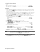
Description
The HP 8566 Spectrum Analyzer is used to monitor the CAL OUTPUT signal of the
HP 8560A. Potentiometer R726 is then adjusted to minimize the displayed noise floor and
thus ensure proper input power to the ECL divide-by-two chip.
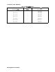
Equipment
Spectrum Analyzer
. . . . . . . . . . . . . . . . . . . . . . . . . . . . . . . . . . . . . . . . . . . . . . . . HP 8566
Adapters
Type N (m) to BNC (f) . . . . . . . . . . . . . . . . . . . . . . . . . . . . . . . . . . . . . . . . . . . 1250-1476
Cables
BNC,122
cm
. . . . . . . . . . . . . . . . . . . . . . . . . . . . . . . . . . . . . . . . . . . . . . . . . . HP 10503A
Procedure
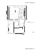
1. Set the HP 8560A (LINE) switch off, disconnect the power cord, and remove the analyzer’s
cover. Fold down the Al5 RF and Al4 Frequency Control assemblies. Prop up the Al4
Frequency Control Assembly.
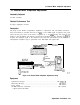
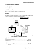
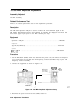
2. Connect the equipment as shown in Figure 2-21.
S
I
GNAL
ANALYZER
I
Al5
Ri
SPECTRUM
FREOIJENCY
CONTROL
,~
Figure 2-21. 600 MHz Amplitude Adjustment Setup
3. Reconnect the power cord and set the (LINE) switch on.
PC
BOARD
PROP
SJl3
2-66 Adjustment Procedures