
User's Manual
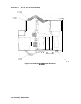

Procedure 6. A6 Power Supply Assembly
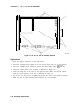
16. Use a screwdriver to remove three standoffs from the A6 Power Supply assembly.
17. Remove the A6 Power Supply assembly by lifting from the regulator
heatsink
toward front
of analyzer.
Replacement
1. Attach the A6 Power Supply assembly to the analyzer’s chassis using the three standoff
screws.
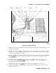
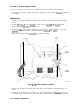
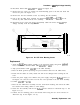
2. Connect
Wl
to
A6J1,
W3 to
A6J2,
fan power wires to
A6J3,
W8 to
A6J4,
and the
line-power jack to
A6JlOl.
See Figure 3-11.
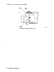
3. Secure the
A6Al
High Voltage assembly to the A6 Power Supply assembly, using three
panhead
screws and washers. Connect ribbon cable
A6AlWl
to A6J5.
4. Snap post-accelerator cable
A6AlW3
to the CRT assembly.
AGAIWI
A6Al
FAN
POWER
L I NE
POWER
SK134
WI
Figure 3-11. A6 Power Supply Connections
5. Ensure that all cables are safely routed and will not be damaged when securing the A6
cover.
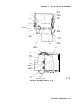
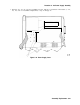
6. Secure the power supply cover shield to the power supply using three
flathead
screws (1).
See Figure 3-12. One end of the cover fits into a slot provided in the rear frame assembly.
3-20 Assembly Replacement