
User's Manual
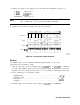
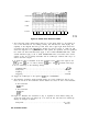
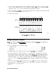

4. Compare the blanking-circuit input signals at the following test points with those
illustrated in Figure 9-3.
BLANKING: J202 pin 15
BLANK: U214 pin 12
VECTOR:
U214 pin 11
U213 pin 13
5. The waveforms in Figure 9-3 must match the timing of the vectors being drawn. To do
this,
U215B
is used to adjust the leading edge, and U215A is used to adjust the trailing
edge. The first six horizontal divisions show the line drawing mode where the VECTOR
pulses are 6
ps apart. The remaining divisions shows character mode (VECTOR pulses
3 ps apart). The BLANK pulses are synchronized to the VECTOR pulses by U214B. The
fourth trace shows the double pulses which delay the leading and trailing edges of the
blanking pulses.
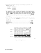
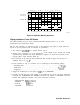
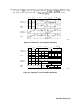
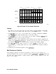
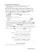
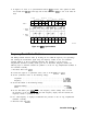
6. Set the oscilloscope to the following settings to expand the first and fourth traces. This
displays how the rising edges of
U213-13
determine the transitions of the blanking pulses.
See Figure 9-4.
Amplitude Scale
. . . . . . . . . . . . . . . . . . . . . . . . . . . . . . . . . . . . . . . . . . . . . . . . .
..4V/div
Amplitude Offset . . . . . . . . . . . . . . . . . . . . . . . . . . . . . . . . . . . . . . . . . . . . . . . . . . . $2.5 V
Sweep Time
. . . . . . . . . . . . . . . . . . . . . . . . . . . . . . . . . . . . . . . . . . . . . . . . . . . . . .
2psfdiv
Delay from Trigger
. . . . . . . . . . . . . . . . . . . . . . . . , . . . . . . . . . . . . . . . . . . . . . . . . . . 96
~LS
Triggering . . . . . . . . . . . . . . . . . . . . . . . . . . . . . . . . . . . . . . . . . . . . . . . . . . . . . . . . External
4.00
V/div
2 50 V 20.0
us/div
0.000
s
BLANK I NG
BLANK
U213-13
SK192
Figure 9-3. Blanking Waveforms
9-6 Controller Section