
User's Manual


Unlocked YTO PLL
Operation
The All YTO is locked to two other oscillators, the Roller PLL’s Main Oscillator and the
Offset PLL’s Sampling Oscillator. For LO spans of 1.01 MHz and above, either the FM or
Main Coil of the YTO is swept directly. For LO spans of 1 MHz and below, the Roller PLL’s
Main Oscillator is swept. The Sampling Oscillator remains fixed-tuned during all sweeps.
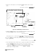
The output of All YTO feeds through the
A7
LO Distribution Amplifier (LODA) to the
A15A2 Sampler. The Offset PLL’s Sampling Oscillator, which drives the sampler, oscillates
between 280 and 298 MHz. The sampler generates harmonics of the Sampling Oscillator and
one of these harmonics mixes with the YTO frequency to generate the Sampler IF frequency.
As a result, the frequency of the Sampler IF is determined by the following equation:
FIF
=
FYTO
-
(Nz&)
Where:
FIF
is the Sampler IF
FYTO
is the YTO’s frequency
N is the desired Sampling Oscillator harmonic
FSAMP
is the Sampling Oscillator frequency
Notice that
FIF
can be positive or negative depending upon whether the Sampling
Oscillator harmonic used is below or above the YTO frequency. Of course, the actual
Sampler IF is always positive, but the sign is carried along as a “bookkeeping” function
which determines which way to sweep the Roller Oscillator (up or down) and what polarity
the YTO error voltage should have (positive or negative) to maintain lock.
To check if a negative Sampler IF is selected, press [CAL), MORE, FREQ DIAGNOSE ,
MAIN ROLLER. If the Main Roller Oscillator frequency is positive, the Sampler IF is also
positive. A negative Main Roller frequency indicates that the Sampler IF is negative.
Notice that the polarity of the YTO loop error voltage (YTO LOOP ERROR) out of
the YTO Loop phase/frequency detector changes as a function of the polarity of the
Sampler IF. That is, for positive Sampler IF’s, an increasing YTO frequency results in
an increasing YTO LOOP ERROR signal. For negative Sampler IF’s, a decreasing YTO
frequency results in a decreasing YTO LOOP ERROR signal. This implies that to maintain
lock in both cases, the sense of YTO LOOP ERROR must be reversed such that, with
a negative Sampler IF, an increasing YTO LOOP ERROR results in an increasing YTO
frequency. This is accomplished with error-sign amplifier, A14U328D. This amplifier can
be firmware-controlled to operate as either an inverting or non-inverting amplifier. Digital
control line ERRSGN
(f
rom A14U313 pin 12) controls the polarity of this amplifier. When
ERRSGN is high, the amplifier has a positive polarity.
In Roller Spans (LO Spans
<l
MHz) the YTO remains locked to the sweeping Roller
Oscillator PLL. Thus, the Sampler IF must always equal the Main Roller Oscillator
frequency (conditions for lock). Since the YTO must always sweep up in frequency, for
Synthesizer Section
lo-23