
User's Manual

13. Demodulator Adjustment
Assembly Adjusted
A4 Log Amplifier Assembly
Related Performance Test
There is no related performance test for this adjustment procedure.
Description
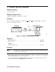
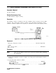
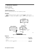
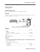
A 5 kHz peak-deviation FM signal is applied to the INPUT
5Ofl.
The detected audio is
monitored by an oscilloscope. FM DEMOD is adjusted to peak the response displayed on the
oscilloscope.
OSCILLOSCOPE
wj
SIGNAL GENERATOR
I
OUTPUT
ADAPTER ADAPTER
Figure 2-16. Demodulator Adjustment Setup
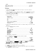
Equipment
AM/FM Signal Generator
.........................................
HP 8640B
Oscilloscope
...................................................
HP 1980A/B
Adapters
Type N (m) to BNC (f) (2 required) . . . . . . . . . . . . . . . . . . . . . . . . . . . . . . . . .1250-1476
SK115
2-52 Adjustment Procedures