HP TouchSmart tx2 Notebook PC Maintenance and Service Guide
© Copyright 2008, 2012 Hewlett-Packard Development Company, L.P. AMD, Athlon, Turion, and combinations thereof, are trademarks of Advanced Micro Devices, Inc. Bluetooth is a trademark owned by its proprietor and used by Hewlett-Packard Company under license. Microsoft, Windows, and Windows Vista are U.S. registered trademarks of Microsoft Corporation. SD Logo is a trademark of its proprietor. The information contained herein is subject to change without notice.
Safety warning notice WARNING! To reduce the possibility of heat-related injuries or of overheating the computer, do not place the computer directly on your lap or obstruct the computer air vents. Use the computer only on a hard, flat surface. Do not allow another hard surface, such as an adjoining optional printer, or a soft surface, such as pillows or rugs or clothing, to block airflow.
iv Safety warning notice
Table of contents 1 Product description ........................................................................................................................................ 1 2 External component identification ................................................................................................................ 5 Top components ................................................................................................................................... 5 Display components .............
Workstation guidelines ..................................................................... 33 Equipment guidelines ....................................................................... 34 Unknown user password ................................................................................................... 35 Component replacement procedures ................................................................................................. 36 Service tag .................................................
12.1-inch, WXGA BrightView display specifications ........................................................................... 77 Hard drive specifications .................................................................................................................... 78 DVD±RW and CD-RW SuperMulti Double-Layer Combo Drive specifications .................................. 79 System DMA specifications .........................................................................................................
10 Power cord set requirements .................................................................................................................. 103 Requirements for all countries or regions ......................................................................................... 103 Requirements for specific countries or regions ................................................................................ 104 11 Recycling .................................................................................
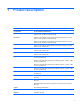
1 Product description Category Description Product Name HP TouchSmart tx2 Notebook PC AMD Turion™ 64 Mobile Technology Ultra Dual-Core ZM-87 processor, 2.40-GHz, 2-MB L2 cache, 800-MHz front side bus (FSB) Processors AMD Turion 64 Mobile Technology Ultra Dual-Core ZM-86 processor, 2.40-GHz, 2-MB L2 cache, 800-MHz front side bus (FSB) AMD Turion 64 Mobile Technology Ultra Dual-Core ZM-85 processor, 2.
Category Description Unified memory architecture (UMA) graphics subsystem memory integrated with system memory; graphics subsystem memory size is dynamic change Panels 12.
Category Description Ethernet ● Integrated Realtek 10/100/1000 (Gigabit Ethernet) ● Ethernet cable included Wireless Integrated wireless local area network (WLAN) options by way of wireless module (includes two 2.4-GHz antennae in display assembly): Broadcom 4322 802.11a/b/g/n + Bluetooth® Broadcom 4322 802.11a/b/g/n Broadcom 4321AGN 802.11a/b/g/draft-n mini-PCI adapter card Broadcom BCM4312 802.11b/g + Bluetooth Broadcom BCM4312 802.
Category Description Power requirements 8-cell, 73-Wh, 2.55-Ah Li-ion battery 6-cell, 55-Wh, 2.55-Ah Li-ion battery 4-cell, 37-Wh, 2.
2 External component identification Top components Display components Item Component Function (1) Convertible hinge Swivels the display and converts the computer from traditional notebook mode into slate mode or vice versa. In slate mode, the display is rotated and folded flat, so that you can view content while carrying the computer. (2) Drive light Blinking: The hard drive or optical drive is being accessed.
Item Component Function (3) Battery light ● On: A battery is charging. ● Blinking: A battery that is the only available power source has reached a low battery level. When the battery reaches a critical battery level, the battery light begins blinking rapidly. ● Off: If the computer is plugged into an external power source, the light is turned off when all batteries in the computer are fully charged.
Keys Item Component Function (1) esc key Displays system information when pressed in combination with the fn key. (2) fn key Executes frequently used system functions when pressed in combination with a function key or the esc key. (3) Windows logo key Displays the Windows Start menu. (4) Windows applications key Displays a shortcut menu for items beneath the pointer. (5) Embedded numeric keypad keys Can be used like the keys on an external numeric keypad.
Pointing devices Item Component Function (1) TouchPad on/off button Enables/disables the TouchPad. (2) TouchPad* Moves the pointer and selects or activates items on the screen. (3) Left TouchPad button* Functions like the left button on an external mouse. (4) TouchPad light ● Blue: TouchPad is enabled. ● Amber: TouchPad is disabled. (5) TouchPad vertical scroll zone Scrolls up or down. (6) Right TouchPad button* Functions like the right button on an external mouse.
Front components Item Component Function (1) Display release latch Opens the computer. (2) Power switch* ● When the computer is off, slide the power switch to the right to turn on the computer. ● When the computer is on, slide the power switch to the right to initiate Sleep. ● When the computer is in the Sleep state, slide the power switch to the right briefly to exit Sleep. ● When the computer is in Hibernation, slide the power switch to the right briefly to exit Hibernation.
Item Component Function (9) Wireless light ● Blue: An integrated wireless device, such as a WLAN device and/or a Bluetooth device, is turned on. ● Amber: All wireless devices are turned off. *This table describes factory settings. For information about changing factory settings, refer to the user guides located in Help and Support. Left-side components 10 Item Component Function (1) Power connector Connects an AC adapter. (2) ExpressCard slot Supports optional ExpressCard/34 cards.
Right-side components Item Component Function (1) Previous/rewind button ● Plays the previous track or chapter when the button is pressed once. ● Rewinds media when the button is pressed simultaneously with the fn key. (2) Play/pause button Plays or pauses media. (3) Next/fast forward button ● Plays the next track or chapter when the button is pressed once. ● Fast forwards media when pressed simultaneously with the fn key. (4) Stop button Stops playback.
Rear components Item Component Function (1) Vent Enables airflow to cool internal components. NOTE: The computer fan starts up automatically to cool internal components and prevent overheating. It is normal for the internal fan to cycle on and off during routine operation. (2) RJ-11 (modem) jack Connects a modem cable. (3) USB ports (2) Connect optional USB devices. (4) Security cable slot Attaches an optional security cable to the computer.
Bottom components Item Component Function (1) Vents (6) Enable airflow to cool internal components. NOTE: The computer fan starts up automatically to cool internal components and prevent overheating. It is normal for the internal fan to cycle on and off during routine operation. (2) Battery release latches (2) Release the battery from the battery bay. (3) Hard drive bay Holds the hard drive and the RTC battery. (4) Optical drive release latch Releases the optical drive from the drive bay.
3 Illustrated parts catalog Service tag When ordering parts or requesting information, provide the computer serial number and model description provided on the service tag. (1) Product name: This is the product name affixed to the front of the computer. (2) Serial number (s/n): This is an alphanumeric identifier that is unique to each product. (3) Part number/Product number (p/n): This number provides specific information about the product's hardware components.
Computer major components Item Description (1a) Display assembly Spare part number 12.
Item (1b) Spare part number 12.
Item Description Spare part number (6b) Memory module compartment cover (includes 2 captive screws, secured with C-clips) (6c) WLAN module compartment cover (includes 1 captive screw, secured with a C-clip) (6d) Hard drive cover (includes one rubber foot and 2 captive screws, secured with C-clips) (6e) Display connector cover (includes 1 captive screw, secured with a C-clip) (7) System board (includes replacement thermal material) 504466-001 (8a) Power switch assembly (includes power switch b
Item Description Spare part number DVD±RW and CD-RW SuperMulti Double-Layer Combo Drive 509074-001 Base enclosure (includes optical drive release assembly, 2 battery release latches, and 4 rubber feet) 506825-001 Rubber Feet Kit (not illustrated, includes 4 base enclosure rubber feet and pen cover) 464821-001 (15) Pen 516454-001 (16) RTC battery 449729-001 (17) Memory modules (DDR2, PC2-6400, 800-MHz) (14) (18) 4096-MB 598855-001 248-MB 598858-001 1024-MB 598861-001 WLAN module Broa
Item Description Spare part number ● 459263-002 For use in Afghanistan, Albania, Algeria, Andorra, Angola, Antigua and Barbuda, Argentina, Armenia, Aruba, Australia, Austria, Azerbaijan, the Bahamas, Bahrain, Bangladesh, Barbados, Belgium, Belize, Benin, Bermuda, Bolivia, Bosnia and Herzegovina, Botswana, Brazil, the British Virgin Islands, Brunei, Bulgaria, Burkina Faso, Burundi, Cameroon, Cape Verde, the Cayman Islands, the Central African Republic, Chad, Chile, Colombia, Comoros, the Congo, Costa Ri
Item (19) (20) 20 Description Spare part number ● For use in Afghanistan, Albania, Algeria, Andorra, Angola, Antigua & Barbuda, Argentina, Armenia, Aruba, Australia, Austria, Azerbaijan, the Bahamas, Bahrain, Bangladesh, Barbados, Belarus, Belgium, Belize, Benin, Bermuda, Bhutan, Bolivia, Bosnia & Herzegovina Botswana, Brazil, the British Virgin Islands, Brunei, Bulgaria, Burkina Faso, Burundi, Cambodia, Cameroon, Cape Verde, the Central African Republic, Chad, Chile, Colombia, Comoros, the Congo, Co
Plastics Kit Item Description Spare part number Plastics Kit 487926-001 (1) ExpressCard slot bezel (2) Hard drive cover (includes 1 rubber foot and 2 captive screws, secured with C-clips) (3) Display connector cover (includes 1 captive screw, secured with a C-clip) (4) WLAN module compartment cover (includes 1 captive screw, secured with a C-clip) (5) Memory module compartment cover (includes 2 captive screws, secured with C-clips) Plastics Kit 21
Mass storage devices Item Description (1) Hard drive (includes hard drive bracket, hard drive connector, and Mylar cover) (2) 22 Spare part number 500-GB, 7200-rpm 634934-001 or 574875-001 320-GB, 7200-rpm 603783-001 320-GB, 5400-rpm 622643-001 160-GB, 7200-rpm 579045-001 Hard Drive Hardware Kit (includes hard drive bracket, hard drive connector, and hard drive screws) 497744-001 Optical drive (includes bezel and bracket) DVD±RW and CD-RW SuperMulti Double-Layer Combo Drive with LightScrib
Miscellaneous parts Description Spare part number 65-watt AC adapter 613149-001 HP protective sleeve 504580-001 or 480105-001 HP Notebook Stand 466337-001 Remote control (fits into ExpressCard slot) 465539-002 Power cords: Argentina 490371-D01 Australia 490371-011 Brazil 490371-201 or 490371-202 Denmark 490371-081 Europe, the Middle East, and Africa (excluding South Africa) 490371-021 India 490371-D61 Israel 490371-BB1 Italy 490371-061 Japan 490371-291 North America 490371-001
Description Spare part number Screw Kit 464116-001 ● Phillips PM3.0×3.0 screws ● Phillips PM2.5×6.0 screws ● Phillips PM2.0×11.0 screws ● Black Phillips PM2.0×7.0 captive screws ● Silver Phillips PM2.0×7.0 screws ● Phillips PM2.0×5.0 captive screws ● Phillips PM2.0×5.0 screws ● Phillips PM2.0×4.0 captive screws ● Phillips PM2.0×4.0 screws ● Phillips PM2.0×3.
Spare part number Description 453730-002 Broadcom 4321AGN 802.
26 Spare part number Description 480105-001 HP Notebook Protective Sleeve 483113-001 Bluetooth module 487330-001 Broadcom 4322 802.11a/b/g/n WLAN module for use in Canada, the Cayman Islands, Guam, Puerto Rico, the U.S. Virgin Islands, and the United States 487330-002 Broadcom 4322 802.
Spare part number Description 490371-D01 Power cord for use in Argentina 490371-D61 Power cord for use in India 497744-001 Hard Drive Hardware Kit (includes hard drive bracket, hard drive connector, and hard drive screws) 504466-001 System board (includes replacement thermal material) 504467-001 12.1-inch, WXGA, BrightView touch-screen display assembly with Web camera, microphones, and WLAN antenna cables 504468-001 12.
28 Spare part number Description 508112-131 Keyboard for use in Portugal 508112-141 Keyboard for use in Turkey 508112-161 Keyboard for use in Latin America 508112-171 Keyboard for use in Saudi Arabia 508112-201 Keyboard for use in Brazil 508112-251 Keyboard for use in Russia 508112-281 Keyboard for use in Thailand 508112-291 Keyboard for use in Japan 508112-A41 Keyboard for use in Belgium 508112-AB1 Keyboard for use in Taiwan 508112-AD1 Keyboard for use in South Korea 508112-B31 Ke
Spare part number Description 613149-001 65-watt AC adapter 622643-001 320-GB, 5400-rpm hard drive (includes hard drive bracket, hard drive connector, and Mylar cover) 634256-001 Thermal pad kit 634934-001 500-GB, 7200-rpm hard drive (includes hard drive bracket, hard drive connector, and Mylar cover) Sequential part number listing 29
4 Removal and replacement procedures Preliminary replacement requirements Tools required You will need the following tools to complete the removal and replacement procedures: ● Magnetic screwdriver ● Phillips P0 and P1 screwdrivers ● Flat-bladed screwdriver Service considerations The following sections include some of the considerations that you should keep in mind during disassembly and assembly procedures.
Cables and connectors CAUTION: When servicing the computer, be sure that cables are placed in their proper locations during the reassembly process. Improper cable placement can damage the computer. Cables must be handled with extreme care to avoid damage. Apply only the tension required to unseat or seat the cables during removal and insertion. Handle cables by the connector whenever possible. In all cases, avoid bending, twisting, or tearing cables.
Grounding guidelines Electrostatic discharge damage Electronic components are sensitive to electrostatic discharge (ESD). Circuitry design and structure determine the degree of sensitivity. Networks built into many integrated circuits provide some protection, but in many cases, ESD contains enough power to alter device parameters or melt silicon junctions. A discharge of static electricity from a finger or other conductor can destroy static-sensitive devices or microcircuitry.
Packaging and transporting guidelines Follow these grounding guidelines when packaging and transporting equipment: ● To avoid hand contact, transport products in static-safe tubes, bags, or boxes. ● Protect ESD-sensitive parts and assemblies with conductive or approved containers or packaging. ● Keep ESD-sensitive parts in their containers until the parts arrive at static-free workstations. ● Place items on a grounded surface before removing items from their containers.
Equipment guidelines Grounding equipment must include either a wrist strap or a foot strap at a grounded workstation. ● When seated, wear a wrist strap connected to a grounded system. Wrist straps are flexible straps with a minimum of one megohm ±10% resistance in the ground cords. To provide proper ground, wear a strap snugly against the skin at all times. On grounded mats with banana-plug connectors, use alligator clips to connect a wrist strap.
Unknown user password If the computer you are servicing has an unknown user password, follow these steps to clear the password. NOTE: These steps also clear CMOS. Before disassembling the computer, follow these steps: 1. Shut down the computer. If you are unsure whether the computer is off or in Hibernation, turn the computer on, and then shut it down through the operating system. 2. Disconnect all external devices connected to the computer. 3. Disconnect the power cord. 4.
Component replacement procedures This chapter provides removal and replacement procedures. There are as many as 47 screws, in 8 different sizes, that must be removed, replaced, or loosened when servicing the computer. Make special note of each screw size and location during removal and replacement. Service tag When ordering parts or requesting information, provide the computer serial number and model description provided on the service tag.
Computer feet Description Spare part number Rubber Feet Kit (includes 4 base enclosure rubber feet and pen cover) 464821-001 The computer feet are adhesive-backed rubber pads. There are four computer feet (1) that adhere to the computer base enclosure, and two computer feet (2) that adhere to the high-capacity battery.
Battery Description Spare part number 8-cell, 73-Wh, 2.55-Ah, Li-ion battery 463650-003 8-cell, 73-Wh, Li-ion battery for use in Japan 534133-291 6-cell, 55-Wh, 2.55-Ah, Li-ion battery 441132-003 4-cell, 37-Wh, 2.55-Ah, Li-ion battery (for use only with computer models equipped with the AMD Turion 64 processor) 441131-003 Before disassembling the computer, follow these steps: 1. Shut down the computer.
Pen Description Spare part number Pen 516454-001 Before removing the pen, follow these steps: 1. Shut down the computer. If you are unsure whether the computer is off or in Hibernation, turn the computer on, and then shut it down through the operating system. 2. Disconnect all external devices connected to the computer. 3. Disconnect the power cord. 4. Remove the battery (see Battery on page 38). Remove the pen: 1. Position the computer with the left side toward you. 2.
Hard drive NOTE: The hard drive spare part kit includes a hard drive bracket, hard drive connector, and Mylar cover. Description Spare part number 500-GB, 7200-rpm 634934-001 or 574875-001 320-GB, 7200-rpm 603783-001 320-GB, 5400-rpm 622643-001 160-GB, 7200-rpm 579045-001 Hard Drive Hardware Kit (includes hard drive bracket, hard drive connector, and hard drive screws) 497744-001 Before removing the hard drive, follow these steps: 1. Shut down the computer.
4. Remove the hard drive cover. NOTE: The hard drive cover is included in the Plastics Kit, spare part number 487926-001. 5. Grasp the Mylar tab (1) on the hard drive and lift the hard drive to disconnect it from the system board. 6. Remove the hard drive (2) from the hard drive bay. 7. If it is necessary to remove the hard drive bracket and connector, remove the two Phillips PM3.0×3.0 hard drive bracket screws (1) from each side of the hard drive. 8.
RTC battery NOTE: Removing the RTC battery and leaving it uninstalled for 5 or more minutes causes all passwords and CMOS settings to be cleared. Description Spare part number RTC battery 449729-001 Before removing the RTC battery, follow these steps: 1. Shut down the computer. If you are unsure whether the computer is off or in Hibernation, turn the computer on, and then shut it down through the operating system. 2. Disconnect all external devices connected to the computer. 3.
Optical drive NOTE: The optical drive spare part kit includes an optical drive bezel. Description Spare part number DVD±RW and CD-RW SuperMulti Double-Layer Combo Drive with LightScribe 509073-001 DVD±RW and CD-RW SuperMulti Double-Layer Combo Drive 509074-001 Optical drive weight saving blank 518183-001 Before removing the optical drive, follow these steps: 1. Shut down the computer.
Memory module Description Spare part number 4096-MB (DDR2, PC2-6400, 800-MHz) 598855-001 2048-MB (DDR2, PC2-6400, 800-MHz) 598858-001 1024-MB (DDR2, PC2-6400, 800-MHz) 598861-001 Before removing the memory module, follow these steps: 1. Shut down the computer. If you are unsure whether the computer is off or in Hibernation, turn the computer on, and then shut it down through the operating system. 2. Disconnect all external devices connected to the computer. 3. Disconnect the power cord. 4.
6. Pull the module (2) away from the slot at an angle and remove it. NOTE: Memory modules are designed with a notch (3) to prevent incorrect insertion into the memory module slot. Reverse this procedure to install a memory module.
WLAN module Description Spare part number Broadcom 4322 802.11a/b/g/n WLAN modules: ● For use in Canada, the Cayman Islands, Guam, Puerto Rico, the U.S.
Description Spare part number Broadcom 4321AGN 802.
3. Lift the right side of the WLAN module compartment cover (2) and swing it to the left. 4. Remove the WLAN module compartment cover. NOTE: The WLAN module compartment cover is included in the Plastics Kit, spare part number 487926-001. 5. Disconnect the WLAN antenna cables (1) from the WLAN module. NOTE: The black WLAN antenna cable is connected to the WLAN module “Main” terminal. The white WLAN antenna cable is connected to the WLAN module “Aux” terminal. 6. Remove the two Phillips PM2.0×3.
Keyboard Description Country or region Spare part number Country or region Spare part number Belgium 508112-A41 Portugal 508112-131 Brazil 508112-201 Russia 508112-251 Canada 508112-121 Saudi Arabia 508112-171 Denmark, Finland, and Norway 508112-DH1 South Korea 508112-AD1 France 508112-051 Spain 508112-071 Germany 508112-041 Switzerland 508112-111 Israel 508112-BB1 Taiwan 508112-AB1 Italy 508112-061 Thailand 508112-281 Japan 508112-291 Turkey 508112-141 Latin America
4. Open the computer. 5. Lift the rear edge of the keyboard and swing it toward you until it rests on the palm rest. 6. Release the zero insertion force (ZIF) connector (1) to which the keyboard cable is attached and disconnect the keyboard cable (2). 7. Remove the keyboard. Reverse this procedure to install the keyboard.
Switch cover Description Spare part number Switch cover (includes display convertible hinge base cover) 506827-001 Before removing the switch cover, follow these steps: 1. Shut down the computer. If you are unsure whether the computer is off or in Hibernation, turn the computer on, and then shut it down through the operating system. 2. Disconnect all external devices connected to the computer. 3. Disconnect the power cord. 4. Remove the battery (see Battery on page 38). 5.
5. Rotate the display clockwise approximately 45 degrees. 6. Lift the left and right front corners of the switch cover (1) until it disengages from the computer. 7. Rotate the switch cover (2) counterclockwise and remove it from the computer. Reverse this procedure to install the switch cover.
Display assembly Description Spare part number 12.1-inch, WXGA, BrightView touch-screen display assembly with Web camera, fingerprint reader, microphones, and WLAN antenna cables 504468-001 12.1-inch, WXGA, BrightView touch-screen display assembly with Web camera, microphones, and WLAN antenna cables 504467-001 Before removing the display assembly, follow these steps: 1. Shut down the computer.
5. Remove the two Phillips PM2.5×6.0 screws (3) that secure the display assembly to the computer. 6. Remove the wireless antenna cables (1) from the routing channel built into the base enclosure. 7. Disconnect the camera cable (2) and the microphone cable (3) from the system board. 8. Turn the computer display-side up, with the front toward you. 9. Open the computer. 10. Remove the display convertible hinge cover (1). CAUTION: Support the display assembly when removing the following screws.
12. Disconnect the display panel cable (3) from the system board. NOTE: As you remove the display assembly, be sure that the display cables and wireless antenna cables move cleanly through the opening (1) in the computer. 13. Lift the display (2) straight up and remove it. Reverse this procedure to install the display assembly.
Top cover Description Spare part number Top cover (includes TouchPad and TouchPad cable, caps lock light board and cable, and top cover bumper pads) 506824-001 Before removing the top cover, follow these steps: 1. Shut down the computer. If you are unsure whether the computer is off or in Hibernation, turn the computer on, and then shut it down through the operating system. 2. Disconnect all external devices connected to the computer. 3. Disconnect the power cord. 4.
5. Release the ZIF connector (2) to which the TouchPad cable is connected and disconnect the TouchPad cable (3). 6. Remove the two Phillips PM2.0×4.0 screws (4) that secure the top cover to the base enclosure. 7. Lift the top cover straight up and remove it. Reverse this procedure to install the top cover.
Power switch assembly Description Spare part number Power switch assembly (includes power switch board cable and actuator switch) 506828-001 Before removing the power switch assembly, follow these steps: 1. Shut down the computer. If you are unsure whether the computer is off or in Hibernation, turn the computer on, and then shut it down through the operating system. 2. Disconnect all external devices connected to the computer. 3. Disconnect the power cord. 4.
3. Remove the display release hook assembly (3). NOTE: The display release hook assemblies are included with the base enclosure spare part kit. 4. Disconnect the power switch board cable (1) from the system board. 5. Remove the power switch board (2) and power switch actuator (3) from the base enclosure. Reverse this procedure to install the power switch assembly.
Bluetooth module Description Spare part number Bluetooth module 483113-001 Bluetooth module cable 487697-001 Before removing the Bluetooth module, follow these steps: 1. Shut down the computer. If you are unsure whether the computer is off or in Hibernation, turn the computer on, and then shut it down through the operating system. 2. Disconnect all external devices connected to the computer. 3. Disconnect the power cord. 4. Remove the battery (see Battery on page 38). 5.
3. Remove the Bluetooth module (3). Reverse this procedure to install the Bluetooth module.
4. Remove the battery (see Battery on page 38). 5. Remove the following components: a. Hard drive (see Hard drive on page 40) b. Memory module compartment cover (see Memory module on page 44) c. Optical drive (see Optical drive on page 43) d. Keyboard (see Keyboard on page 49) e. Switch cover (see Switch cover on page 51) f. Display assembly (see Display assembly on page 53) g. Top cover (see Top cover on page 56) h.
3. Release the ZIF connector (1) to which the audio/infrared board cable is connected and disconnect the audio/infrared board cable (2) from the system board. 4. Use the optical drive connector (1) to lift the left side of the system board (2) until the power connector (3) is clear of the base enclosure. 5. Pull the system board (4) away from the top cover at an angle and remove it. Reverse this procedure to install the system board.
Pen holder and pen eject assembly Description Spare part number Pen holder and pen eject assembly 506826-001 Before removing the pen holder and pen eject assembly, follow these steps: 1. Shut down the computer. If you are unsure whether the computer is off or in Hibernation, turn the computer on, and then shut it down through the operating system. 2. Disconnect all external devices connected to the computer. 3. Disconnect the power cord. 4. Remove the battery (see Battery on page 38). 5.
4. Remove the pen holder (4). Reverse this procedure to install the pen holder and pen eject assembly. Audio/infrared board Description Spare part number Audio/infrared board (includes audio/infrared board cable) 441144-001 Before removing the audio/infrared board, follow these steps: 1. Shut down the computer. If you are unsure whether the computer is off or in Hibernation, turn the computer on, and then shut it down through the operating system. 2.
i. System board (see System board on page 61) j. Pen holder (see Pen holder and pen eject assembly on page 64) Remove the audio/infrared board: 1. Remove the two Phillips PM2.0×3.0 screws (1) that secure the audio/infrared board to the system board. 2. Release the audio/infrared board (2) by sliding it away from you until the connectors on the front of the board disengage from the openings in the base enclosure. 3. Remove the audio/infrared board (3).
Fan/heat sink assembly Description Spare part number Fan/heat sink assembly (includes thermal material) 487925-001 NOTE: To properly ventilate the computer, allow at least a 7.6-cm (3-inch) clearance on the right side and rear panel of the computer. The computer uses an electric fan for ventilation. The fan is controlled by a temperature sensor and is designed to turn on automatically when high temperature conditions exist.
3. Remove the fan/heat sink assembly (3). NOTE: Due to the adhesive quality of the thermal material located between the fan/heat sink assembly and system board components, it may be necessary to move the fan/heat sink assembly from side to side to detach the assembly. NOTE: The thermal material should be thoroughly cleaned from the surfaces of the fan/heat sink assembly (1) and the system board components (2) each time the fan/heat sink assembly is removed.
Processor NOTE: The processor spare part kit includes replacement thermal material. Desription Spare part number AMD Turion 64 Mobile Technology Dual-Core ZM-87 processor (2.40-GHz, 1-MB L2 cache, 800-MHz FSB) 572564-001 AMD Turion Ultra 64 Mobile Technology Ultra Dual-Core ZM-86 processor (2.40-GHz, 1-MB L2 cache, 800-MHz FSB) 507974-001 AMD Turion 64 Mobile Technology Dual-Core ZM-85 processor (2.
4. Remove the battery (see Battery on page 38). 5. Remove the following components: a. Hard drive (see Hard drive on page 40) b. Memory module compartment cover (see Memory module on page 44) c. Optical drive (see Optical drive on page 43) d. Keyboard (see Keyboard on page 49) e. Switch cover (see Switch cover on page 51) f. Display assembly (see Display assembly on page 53) g. Top cover (see Top cover on page 56) h. Power switch assembly (see Power switch assembly on page 58) i.
5 Setup Utility WARNING! Only authorized technicians trained by HP should repair this equipment. All troubleshooting and repair procedures are detailed to allow repair at only the subassembly or module level. Because of the complexity of the individual boards and subassemblies, do not attempt to make repairs at the component level or modify any printed wiring board. Improper repairs can create a safety hazard.
Changing the language of the Setup Utility The following procedure explains how to change the language of the Setup Utility. If the Setup Utility is not already running, begin at step 1. If the Setup Utility is already running, begin at step 2. 1. To start the Setup Utility, turn on or restart the computer, and then press f10 while “Press to enter setup” is displayed in the lower-left corner of the screen. 2. Use the arrow keys to select System Configuration > Language, and then press enter. 3.
Restoring default settings in the Setup Utility The following procedure explains how to restore the Setup Utility default settings. If the Setup Utility is not already running, begin at step 1. If the Setup Utility is already running, begin at step 2. 1. To start the Setup Utility, turn on or restart the computer, and then press f10 while “Press to enter setup” is displayed in the lower-left corner of the screen. 2. Select Exit > Load Setup Defaults, and then press enter. 3.
Closing the Setup Utility You can close the Setup Utility with or without saving changes. ● To close the Setup Utility and save your changes from the current session, use either of the following procedures: ◦ Press f10, and then follow the instructions on the screen. — or — ◦ If the Setup Utility menus are not visible, press esc to return to the menu display. Then use the arrow keys to select Exit > Exit Saving Changes, and then press enter.
System Configuration menu Select To do this Language Support Change the Setup Utility language. Enhanced SATA support (select models only) Enable/disable enhanced SATA mode. Boot Options Set the following boot options: ● f10 and f12 Delay (sec.)―Set the delay for the f10 and f12 functions of the Setup Utility in intervals of 5 seconds each (0, 5, 10, 15, 20). ● CD-ROM boot―Enable/disable boot from CD-ROM. ● Floppy boot―Enable/disable boot from Floppy.
6 Specifications Computer specifications Metric U.S. Height (front to back) 3.1 to 3.9 cm 1.22 to 1.54 in Width 30.6 cm 12.05 in Depth 22.4 cm 8.82 in Weight (with optical drive, hard drive, and battery) 1.95 kg 4.29 lbs Dimensions Input power Operating voltage 18.5 V dc @ 3.5 A - 65 W Operating current 3.
Metric Nonoperating U.S. 1.50 g zero-to-peak, 10 Hz to 500 Hz, 0.5 oct/min sweep rate NOTE: Applicable product safety standards specify thermal limits for plastic surfaces. The computer operates well within this range of temperatures. 12.1-inch, WXGA BrightView display specifications Metric U.S. Height 16.2 cm 6.4 in Width 26.0 cm 10.2 in Diagonal 30.6 cm 12.1 in Number of colors Up to 16.
Hard drive specifications 500-GB* 320-GB* 160-GB* Height 9.5 mm 9.5 mm 9.
DVD±RW and CD-RW SuperMulti Double-Layer Combo Drive specifications Applicable disc Read: Write: CD-DA, CD+(E)G, CD-MIDI, CD-TEXT, CD-ROM, CD-ROM XA, MIXED MODE CD, CD-I, CD-I Bridge (Photo-CD, Video CD), Multisession CD (PhotoCD, CD-EXTRA, Portfolio, CD-R, CDRW), CD-R, CD-RW, DVD-ROM (DVD-5, DVD-9, DVD-10, DVD-18), DVD-R, DVD-RW, DVD+R, DVD+RW, DVD-RAM CD-R and CD-RW Access time CD DVD Random < 175 ms < 230 ms Cache buffer 2 MB DVD+R, DVD+RW, DVD-R, DVD-RW, DVD-RAM Data transfer rate 24X CD-R
System DMA specifications Hardware DMA System function DMA0 Not applicable DMA1* Not applicable DMA2* Not applicable DMA3 Not applicable DMA4 Direct memory access controller DMA5* Available for PC Card DMA6 Not assigned DMA7 Not assigned *PC Card controller can use DMA 1, 2, or 5.
System interrupt specifications Hardware IRQ System function IRQ0 System timer IRQ1 Standard 101-/102-Key or Microsoft Natural Keyboard IRQ2 Cascaded IRQ3 USB2 Enhanced Host Controller—24CD IRQ4 COM1 IRQ5* Conexant AC—SMBus Controller—24C3 Data Fax Modem with SmartCP IRQ6 Diskette drive IRQ7* Parallel port IRQ8 System CMOS/real-time clock IRQ9* Microsoft ACPI-compliant system IRQ10* USB UHCI controller—24C2 Graphic Controller Realtek RTL8139 Family PCI Fast Ethernet Controller IRQ11
System I/O address specifications 82 I/O address (hex) System function (shipping configuration) 000 - 00F DMA controller no. 1 010 - 01F Unused 020 - 021 Interrupt controller no.
I/O address (hex) System function (shipping configuration) 220 - 22F Entertainment audio 230 - 26D Unused 26E - 26 Unused 278 - 27F Unused 280 - 2AB Unused 2A0 - 2A7 Unused 2A8 - 2E7 Unused 2E8 - 2EF Reserved serial port 2F0 - 2F7 Unused 2F8 - 2FF Infrared port 300 - 31F Unused 320 - 36F Unused 370 - 377 Secondary diskette drive controller 378 - 37F Parallel port (LPT1/default) 380 - 387 Unused 388 - 38B FM synthesizer—OPL3 38C - 3AF Unused 3B0 - 3BB VGA 3BC - 3BF Rese
System memory map specifications 84 Size Memory address System function 640 KB 00000000-0009FFFF Base memory 128 KB 000A0000-000BFFFF Video memory 48 KB 000C0000-000CBFFF Video BIOS 160 KB 000C8000-000E7FFF Unused 64 KB 000E8000-000FFFFF System BIOS 15 MB 00100000-00FFFFFF Extended memory 58 MB 04800000-07FFFFFF Super extended memory 58 MB 04800000-07FFFFFF Unused 2 MB 08000000-080FFFFF Video memory (direct access) 4 GB 08200000-FFFEFFFF Unused 64 KB FFFF0000-FFFFFFFF Sy
7 Screw listing This section provides specification and reference information for the screws and screw locks used in the computer. All screws and screw locks listed in this section are available in the Screw Kit, spare part number 464116-001. Phillips PM3.0×3.0 screw Color Quantity Length Thread Head width Silver 4 3.0 mm 3.0 mm 5.0 mm Where used: 4 screws that secure the hard drive bracket to the hard drive Phillips PM3.0×3.
Phillips PM2.0×7.0 screw Color Quantity Length Thread Head width Black 9 7.0 mm 2.0 mm 4.
Phillips PM2.0×4.0 screw Color Quantity Length Thread Head width Silver 10 4.0 mm 2.0 mm 4.5 mm Where used: 2 screws that secure the top cover to the computer Where used: 2 screws that secure the power switch board to the base enclosure Phillips PM2.0×4.
Where used: 2 screws that secure the audio/infrared board to the base enclosure Where used: 4 screws that secure the fan/heat sink assembly to the system board 88 Chapter 7 Screw listing
Phillips PM2.0×5.0 captive screw Color Quantity Length Thread Head width Black 6 5.0 mm 2.0 mm 4.
Black Phillips PM2.0×3.0 screw Color Quantity Length Thread Head width Black 5 3.0 mm 2.0 mm 4.
Phillips PM2.0×11.0 screw Color Quantity Length Thread Head width Black 4 11.0 mm 2.0 mm 4.5 mm Where used: 4 screws that secure the keyboard to the computer Phillips PM2.0×11.
Phillips PM2.5×6.0 screw Color Quantity Length Thread Head width Silver 4 6.0 mm 2.5 mm 5.
Silver Phillips PM2.0×3.0 screw Color Quantity Length Thread Head width Silver 5 3.0 mm 2.0 mm 4.5 mm Where used: (1) One screw that secures the display release hook to the base enclosure (2) One screw that secures the Bluetooth module to the base enclosure Where used: 3 screws that secure the pen eject assembly and pen holder to the base enclosure Silver Phillips PM2.0×3.
8 Backup and recovery Recovering system information Tools provided by the operating system and Recovery Manager software are designed to help you with the following tasks for safeguarding your information and restoring it in case of a system failure: ● Backing up your information regularly to protect your important system files. ● Making a set of recovery discs (Recovery Manager software feature).
● Number each disc before inserting it into the computer optical drive. ● If necessary, you can exit the program before you have finished creating the recovery discs. The next time you open Recovery Manager, you will be prompted to continue the disc creation process. To create a set of recovery discs: 1. Select Start > All Programs > Recovery Manager > Recovery Manager. Recovery Manager opens. 2. Click Advanced Options.
Backup suggestions ● Create a set of recovery discs using Recovery Manager. ● Create system restore points using the Windows System Restore feature, and periodically copy them to disc. ● Store personal files in the Documents folder and back up these folders periodically. ● Back up templates stored in their associated programs. ● Save customized settings in a window, toolbar, or menu bar by taking a screen shot of your settings.
5. Click Create. The System Protection window opens. 6. Follow the on-screen instructions. Restore to a previous date and time To revert to a restore point (created at a previous date and time), when the computer was functioning optimally, follow these steps: 1. Select Start > Control Panel > System and Maintenance > System. 2. In the left pane, click System protection. 3. Click the System Protection tab. 4. Click the System Restore button, and then click Next. The System Restore window opens.
To restore the system from the partition, follow these steps: 1. Access Recovery Manager in either of the following ways: ● Select Start > All Programs > Recovery Manager > Recovery Manager. –or– ● Restart the computer and press f11 while the “Press for recovery” message is displayed on the screen. Then select Recovery Manager. Recovery Manager opens. 98 2. Click Advanced Options. 3. Click System recovery, and then click Next. 4. Follow the on-screen instructions.
9 Connector pin assignments Audio-in (microphone) Pin Signal 1 Audio signal in 2 Audio signal in 3 Ground Audio-out (headphone) Pin Signal 1 Audio out, left channel 2 Audio out, right channel 3 Ground Audio-in (microphone) 99
External monitor Pin Signal 1 Red analog 2 Green analog 3 Blue analog 4 Not connected 5 Ground 6 Ground analog 7 Ground analog 8 Ground analog 9 +5 VDC 10 Ground 11 Monitor detect 12 DDC 2B data 13 Horizontal sync 14 Vertical sync 15 DDC 2B clock 100 Chapter 9 Connector pin assignments
RJ-11 (modem) Pin Signal 1 Unused 2 Unused 3 Ring 4 Tip 5 Unused 6 Unused RJ-45 (network) Pin Signal 1 Transmit + 2 Transmit - 3 Receive + 4 Unused 5 Unused 6 Receive - 7 Unused 8 Unused RJ-11 (modem) 101
S-Video-out Pin Signal 1 S-VHS color (C) signal 2 Composite video signal 3 S-VHS intensity (Y) signal 4 S-VHS color ground 5 TV-CD 6 S-VHS intensity ground 7 Composite video ground Universal Serial Bus Pin Signal 1 +5 VDC 2 Data - 3 Data + 4 Ground 102 Chapter 9 Connector pin assignments
10 Power cord set requirements The wide range input feature of the computer permits it to operate from any line voltage from 100 to 120 volts AC or from 220 to 240 volts AC. The 3-conductor power cord set included with the computer meets the requirements for use in the country or region where the equipment is purchased. Power cord sets for use in other countries or regions must meet the requirements of the country or region where the computer is used.
Requirements for specific countries or regions Region Accredited agency Applicable note number Australia EANSW 1 Austria OVE 1 Belgium CEBC 1 Canada CSA 2 Denmark DEMKO 1 Finland FIMKO 1 France UTE 1 Germany VDE 1 Italy IMQ 1 Japan METI 3 The Netherlands KEMA 1 Norway NEMKO 1 The People's Republic of China CCC 5 South Korea EK 4 Sweden SEMKO 1 Switzerland SEV 1 Taiwan BSMI 4 The United Kingdom BSI 1 The United States UL 2 1.
11 Recycling Battery When a battery has reached the end of its useful life, do not dispose of the battery in general household waste. Follow the local laws and regulations in your area for computer battery disposal. Display WARNING! The backlight contains mercury. Caution should be exercised when removing and handling the backlight to avoid damaging this component and causing exposure to the mercury. CAUTION: The procedures in this chapter can result in damage to display components.
Perform the following steps to disassemble the display assembly: 1. Remove all screw covers (1) and screws (2) that secure the display bezel to the display assembly. 2. Lift up and out on the left and right inside edges (1) and the top and bottom inside edges (2) of the display bezel until the bezel disengages from the display assembly. 3. Remove the display bezel (3).
4. Disconnect all display panel cables (1) from the display inverter and remove the inverter (2). 5. Remove all screws (1) that secure the display panel assembly to the display enclosure. 6. Remove the display panel assembly (2) from the display enclosure. 7. Turn the display panel assembly upside down. 8. Remove all screws that secure the display panel frame to the display panel. 9. Use a sharp-edged tool to cut the tape (1) that secures the sides of the display panel to the display panel frame.
10. Remove the display panel frame (2) from the display panel. 11. Remove the screws (1) that secure the backlight cover to the display panel. 12. Lift the top edge of the backlight cover (2) and swing it outward. 13. Remove the backlight cover. 14. Turn the display panel right-side up.
15. Remove the backlight cables (1) from the clip (2) in the display panel. 16. Turn the display panel upside down. 17. Remove the backlight frame from the display panel. WARNING! The backlight contains mercury. Exercise caution when removing and handling the backlight to avoid damaging this component and causing exposure to the mercury. 18. Remove the backlight from the backlight frame.
19. Disconnect the display cable (1) from the LCD panel. 20. Remove the screws (2) that secure the LCD panel to the display rear panel. 21. Release the LCD panel (3) from the display rear panel. 22. Release the tape (4) that secures the LCD panel to the display rear panel. 23. Remove the LCD panel. 24. Recycle the LCD panel and backlight.
Index A AC adapter, spare part number 23, 29 administrator password 74 advanced Setup Utility features 73 antenna, locations 6 applications key, Windows 7 audio, product description 2 audio-in jack location 9 pin assignments 99 audio-out jack location 9 pin assignments 99 audio-out S/PDIF jack 9 audio/infrared board removal 65 spare part number 17, 24, 65 B backup 95 base enclosure, spare part number 18, 27 battery removal 38 spare part numbers 20, 24, 25, 38 battery bay 13 battery light 6 battery release
drive light 5 drives, boot order 75 drives, preventing damage 31 DVD±RW and CD-RW DoubleLayer Combo Drive precautions 31 removal 43 spare part numbers 17, 18, 22, 28, 43 specifications 79 E electrostatic discharge 32 enhanced SATA support 75 esc key 7 Ethernet, product description 3 expansion port 3 11 ExpressCard slot 10 ExpressCard slot bezel illustrated 21 removal 62 external media cards, product description 3 external monitor port location 11 pin assignments 100 F fan/heat sink assembly removal 67 spare
O operating system, product description 4 optical drive location 10 precautions 31 product description 2 removal 43 spare part numbers 17, 22, 43 specifications 79 optical drive light 10 optical drive release latch 13 optical drive weight saving blank, spare part number 28, 43 P packing guidelines 33 password clearing 35 passwords 74 pen removal 39 spare part number 18, 28, 39 pen eject assembly removal 64 spare part number 17, 27, 64 pen holder 11 removal 64 spare part number 17, 27, 64 pen tether hole 11
slots Digital Media Slot 10 ExpressCard 10 software, safeguarding information 94 specifications computer 76 display 77 DVD±RW and CD-RW DoubleLayer Combo Drive 79 hard drive 78 I/O addresses 82 interrupts 81 memory map 84 optical drive 79 system DMA 80 static-shielding materials 34 stop button 11 switch cover removal 51 spare part number 16, 27, 51 system board removal 61 spare part number 17, 27, 61 System Configuration menu 75 system DMA 80 system information 72, 74 system memory map 84 system recovery 94