Troubleshooting Guide HP t630 Thin Client
© Copyright 2016 HP Development Company, L.P. Windows is a registered trademark or trademark of Microsoft Corporation in the United States and/or other countries. The information contained herein is subject to change without notice. The only warranties for HP products and services are set forth in the express warranty statements accompanying such products and services. Nothing herein should be construed as constituting an additional warranty.
About this book WARNING! Text set off in this manner indicates that failure to follow directions could result in bodily harm or loss of life. CAUTION: Text set off in this manner indicates that failure to follow directions could result in damage to equipment or loss of information. NOTE: Text set off in this manner provides important supplemental information.
iv About this book
Table of contents 1 Product features ........................................................................................................................................... 1 Front panel components ........................................................................................................................................ 2 Rear panel components .........................................................................................................................................
Computer Setup—Power .................................................................................................................. 29 Computer Setup—Advanced ............................................................................................................. 30 Changing BIOS Settings from the HP BIOS Configuration Utility (HPBCU) .......................................................... 31 Appendix B Diagnostics and troubleshooting .............................................................
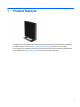
1 Product features This guide describes the features of the thin client. For more information about the hardware and software installed on this thin client, go to http://www.hp.com/go/quickspecs and search for this thin client. Various options are available for your thin client. For more information about some of the available options, go to the HP website at http://www.hp.com and search for your specific thin client.
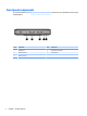
Front panel components For more information, go to http://www.hp.com/go/quickspecs and search for your specific thin client to find the QuickSpecs. 2 Item Component Item Component 1 Headset jack 4 Flash drive activity LED 2 USB 3.0 ports (2) 5 Power button 3 USB 2.
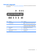
Rear panel components For more information, go to http://www.hp.com/go/quickspecs/ and search for your specific thin client to find the QuickSpecs. Item Component Item Component 1 RJ-45 (network) jack 7 Audio-out (headphone)/Audio-in (microphone) combo jack 2 PS/2 keyboard port 8 Optional port.
Serial number location Every thin client includes a unique serial number located as shown in the following illustration. Have this number available when contacting HP customer service for assistance.
2 Setup Warnings and cautions Before performing upgrades be sure to carefully read all of the applicable instructions, cautions, and warnings in this guide. WARNING! fire: To reduce the risk of personal injury or equipment damage from electric shock, hot surfaces, or Disconnect the AC power cord from the AC outlet and allow the internal system components to cool before you touch them. Do not plug telecommunications or telephone connectors into the network interface controller (NIC) receptacles.
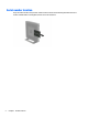
Attaching the stand CAUTION: Unless the thin client is mounted with the HP Quick Release, it must be operated with the stand attached to ensure proper airflow around the thin client. Adjusting the stand The stand can be adjusted into two configurations: square for the horizontal position and rectangular for the vertical position. Take the stand apart by removing the two short pieces connecting the two sides.
● 7. b. Position the stand over the bottom of the thin client and line up the captive screws in the stand with the screw holes in the thin client. c. Tighten the captive screws securely. Attach the stand to the right side of the thin client to use it in the horizontal orientation. a. Lay the thin client down with the right side up and locate the two screw holes in the grid on the right side of the thin client. b.
NOTE: An optional Quick Release mounting bracket is available from HP for mounting the thin client to a wall, desk, or swing arm. When the mounting bracket is used, do not install the thin client with the I/O ports oriented towards the ground. Connecting the AC power cord 1. Connect the round end of the power supply cord to the power supply connector on the rear of the thin client (1). 2. Use the slot (2) on the side of the retractable AC power cord retention hook to pull the hook out. 3.
Securing the thin client These thin clients are designed to accept a security cable. The security cable prevents unauthorized removal of the thin client, as well as preventing access to the secure compartment. To order this option, go to the HP website at http://www.hp.com and search for your specific thin client. 1. Locate the security cable slot on the back panel. 2. Insert the security cable lock into the slot, and then use the key to lock it.
3 Hardware changes Warnings and cautions Before performing upgrades be sure to carefully read all of the applicable instructions, cautions, and warnings in this guide. WARNING! fire: To reduce the risk of personal injury or equipment damage from electric shock, hot surfaces, or Energized and moving parts are inside. Disconnect power to the equipment before removing the enclosure. Allow the internal system components to cool before you touch them.
4. Disconnect the AC power cord from the AC outlet, and disconnect any external devices. CAUTION: Regardless of the power-on state, voltage is always present on the system board as long as the system is plugged into an active AC outlet. You must disconnect the AC power cord to avoid damage to the internal components of the thin client. 5. Remove the stand from the thin client. 6. Lay the unit flat on a stable surface with the right side up. 7.
Replacing the access panel To replace the access panel: 12 1. Position the access panel on the chassis, approximately 6 mm (.24 in) inside the edge of the chassis. Slide the panel toward the front of the chassis (1) until it locks into place. 2. Move the access panel latch (2) to the left to secure the access panel. 3.
Locating internal components Item Component Item Component 1 Battery 5 Configurable serial port jumpers 2 System memory DIMM1 6 USB 3.0 port 3 System memory DIMM2 7 M.2 socket for a 42 mm, 60 mm, or 80 mm M.2 primary storage module 4 Clear CMOS button 8 M.2 socket for a 42 mm M.
Replacing an M.2 storage module Two M.2 storage module sockets can be installed in the thin client: ● A 42 mm, 60 mm, or 80 mm M.2 primary storage module may be installed in one socket. ● A 42 mm M.2 secondary storage module may be installed in the other socket. To remove an M.2 flash storage module: 1. Remove/disengage any security devices that prohibit opening the thin client. 2. Remove all removable media, such as USB flash drives, from the thin client. 3.
11. Pull the screw kit off of the storage module and attach it to the replacement storage module. 12. Slide the new storage module into the M.2 socket on the system board and press the module connectors firmly into the socket. NOTE: A storage module can be installed in only one way. Replacing an M.
13. Press the storage module down and use a screwdriver to tighten the screw and secure the module to the system board. 14. Replace and latch the access panel, and then reinstall the rear I/O panel. See Removing and replacing the access panel on page 10. 15. Replace the thin client stand. 16. Reconnect the AC power cord and turn on the thin client. 17. Lock any security devices that were disengaged when the thin client access panel was removed.
10. To insert the new battery, slide one edge of the replacement battery under the holder’s lip with the positive side up. Push the other edge down until the clamp snaps over the other edge of the battery (2). 11. Replace and latch the access panel, and then reinstall the rear I/O panel. See Removing and replacing the access panel on page 10. 12. Replace the thin client stand. 13. Reconnect the AC power cord and turn on the thin client. 14.
Installing an internal USB flash drive There is one USB 3.0 flash drive port on the system board. To install a USB flash drive: 1. Remove/disengage any security devices that prohibit opening the thin client. 2. Remove all removable media, such as USB flash drives, from the thin client. 3. Turn off the thin client properly through the operating system, and then turn off any external devices. 4. Disconnect the AC power cord from the AC outlet, and disconnect any external devices. 5.
Upgrading system memory The memory socket on the system board is populated with one memory module. To achieve the maximum memory support, you can populate each memory socket with up to 16 GB of memory each (32 GB total). For proper system operation, the memory module must adhere to the following specifications: ● Industry-standard 260-pin Small Outline DIMM (SODIMM) ● Unbuffered non-ECC PC4-17000 DDR4-1866 MHz ● 1.
6. Position the unit flat on a stable surface with the right side up. 7. Remove the thin client access panel. See Removing and replacing the access panel on page 10. WARNING! To reduce risk of personal injury from hot surfaces, allow the internal system components to cool before you touch them. 8. Locate the memory module on the system board. See Locating internal components on page 13. 9.
Configuring the serial port One configurable powered serial port is standard on the thin client. Devices that support a powered serial interface do not require an external power source. To determine which serial port pin powered a specific device, refer to the specification for that device. The default setting for the powered serial port is not powered.
Serial port functionality CAUTION: To prevent severe equipment damage, carefully verify the location of the serial port jumper before you configure it. See Locating configurable serial port jumpers on page 21 for locations.
Configuring the serial port 1. Remove/disengage any security devices that prohibit opening the thin client. 2. Remove all removable media, such as USB flash drives, from the thin client. 3. Turn off the thin client properly through the operating system, and then turn off any external devices. 4. Unplug the power cord from the AC outlet, and disconnect any external devices.
A Computer Setup (F10) Utility, BIOS Settings Computer Setup (F10) Utilities Use Computer Setup (F10) Utility to do the following: ● Change factory default settings. ● Set the system date and time. ● Set, view, change, or verify the system configuration, including settings for processor, graphics, memory, audio, storage, communications, and input devices. ● Modify the boot order of bootable devices such as solid-state drives or USB flash media devices.
5. Use the arrow (left and right) keys to select the appropriate heading. Use the arrow (up and down) keys to select the option you want, then press enter. To return to the Computer Setup Utilities menu, press esc. 6. To apply and save changes, select File > Save Changes and Exit. ● If you have made changes that you do not want applied, select Ignore Changes and Exit. ● To reset to factory settings, select Apply Defaults and Exit. This option will restore the original factory system defaults.
Computer Setup—File NOTE: 26 Support for specific Computer Setup options may vary depending on the hardware configuration. Option Description System Information Lists: ● Product name ● SKU number ● System Board CT Number ● Processor type ● Processor speed ● Processor stepping ● Cache size (L1/L2) ● Memory size ● Integrated MAC ● System BIOS ● Chassis serial number ● Asset tracking number About Displays copyright notice.
Computer Setup—Storage Option Description Device Configuration Lists all installed BIOS-controlled storage devices. When a device is selected, detailed information and options are displayed. The following options may be presented: Hard Disk: Size, model, firmware version, serial number. Storage Options SATA Emulation CAUTION: SATA emulation changes may prevent access to existing drive data and degrade or corrupt established volumes.
Computer Setup—Security NOTE: Support for specific Computer Setup options may vary depending on the hardware configuration. Table A-1 Computer Setup—Security Option Description Setup Password Allows you to set and enable a setup (administrator) password. NOTE: If the setup password is set, it is required to change Computer Setup options, flash the ROM, and make changes to certain plug and play settings under Windows. Power-On Password Allows you to set and enable a power-on password.
Table A-1 Computer Setup—Security (continued) Option Description Tool-less BIOS Update Allows you to enable the tool-less BIOS feature, in which BIOS invokes HpBiosUpdate.efi (HpBiosMgmt.efi) and related toolsets in internal/external storage during the last stage of POST. System Security ● BIOS Update (enable/disable) ● BIOS Image File Name Provides these options: ● Data Execution Prevention (enable/disable) - Helps prevent operating system security breaches. Default is enabled.
Computer Setup—Advanced NOTE: Support for specific Computer Setup options may vary depending on the hardware configuration. Table A-3 Computer Setup—Advanced (for advanced users) Option Heading Power-On Options Allows you to set: ● POST messages (enable/disable) – Default is disabled. ● Press the ESC key for Startup Menu (Displayed/Hidden). ● After Power Loss (off/on/previous state) – Default is Power off.
Changing BIOS Settings from the HP BIOS Configuration Utility (HPBCU) Some BIOS settings may be changed locally within the operating system without having to go through the F10 utility. This table identifies the items that can be controlled with this method. For more information about the HP BIOS Configuration Utility, see the HP BIOS Configuration Utility (BCU) User Guide at www.hp.com.
32 BIOS setting Default value Other values TPM Device Disable Enable TPM State Enable Disable TPM Clear Do not reset Reset Legacy Support Enable Disable (Note: The default value may be varied depends on the OS) Secure Boot Disable Enable (Note: The default value may be varied depends on the OS) Clear Secure Boot Keys Don’t Clear Clear Key Ownership HP Keys Custom Keys Fast Boot Disable Enable (Note: The default value may be varied depends on the OS) Setup Browse Mode Enable Dis
B Diagnostics and troubleshooting LEDs Table B-1 Power and IDE Flash Activity LEDs LED Status Power LED Off When the unit is plugged into the wall socket and the Power LED is off, the unit is powered off. However, the network can trigger a Wake On LAN event in order to perform management functions. Power LED On Displays during boot sequence and while the unit is on.
Wake-on LAN Wake-on LAN (WOL) allows a computer to be turned on or resumed from sleep or hibernation state by a network message. You can enable or disable WOL in Computer Setup using the S5 Maximum Power Savings setting. To enable or disable WOL: 1. Turn on or restart the computer. 2. Press either esc or F10 while the “Press the ESC key for Startup Menu” message is displayed at the bottom of the screen.
Resetting the Setup and Power-on passwords You can reset the Setup and Power-on passwords as follows: 1. Turn off the computer and disconnect the power cord from the power outlet. 2. Remove the side access panel and the metal side cover. 3. Remove the password jumper from the system board header labeled PSWD/E49. 4. Replace the metal side cover and the side access panel. 5. Connect the computer to AC power, and then turn on the computer. 6.
Interpreting POST diagnostic front panel LEDs and audible codes This section covers the front panel LED codes as well as the audible codes that may occur before or during POST that do not necessarily have an error code or text message associated with them. WARNING! When the computer is plugged into an AC power source, voltage is always applied to the system board.
Table B-3 Diagnostic front panel LEDs and audible codes (continued) Activity Red Power LED flashes six times, once every second, followed by a two second pause. Beeps stop after fifth iteration but LEDs continue until problem is solved. Beeps 6 Possible Cause Pre-video graphics error. Recommended Action 3. Replace third-party memory with HP memory. 4. Replace the system board. For systems with a graphics card: 1. Reseat the graphics card. 2. Replace the graphics card. 3.
POST numeric codes and text messages This section covers those POST errors that have numeric codes associated with them. The section also includes some text messages that may be encountered during POST. NOTE: The computer will beep once after a POST text message is displayed on the screen. Table B-4 Numeric Codes and Text Messages Control panel message Description Recommended action 103-System Board Failure DMA or timers. 1. Clear CMOS. 2. Remove expansion boards. 3. Replace the system board.
Table B-4 Numeric Codes and Text Messages (continued) Control panel message Description Recommended action 512-Chassis, Rear Chassis, or Front Chassis Fan not Detected Chassis, rear chassis, or front chassis fan is not connected or may have malfunctioned. 1. Reseat chassis, rear chassis, or front chassis fan. 2. Reseat fan cable. 3. Replace chassis, rear chassis, or front chassis fan. 1. Reseat front chassis fan. 2. Reseat fan cable. 3. Replace front chassis fan.
Troubleshooting Basic troubleshooting If the thin client is experiencing operating problems or will not power on, review the following items. Table B-5 Power-on troubleshooting Issue Procedures The thin client unit is experiencing operating problems. Ensure that the following connectors are securely plugged into the thin client unit: The thin client unit does not power on. 1. Verify that the power supply is good by installing it on a known working unit and testing it.
Diskless (No-Flash) unit troubleshooting This section is only for those units that do not have ATA Flash capability. Because there is no ATA Flash in this model the boot priority sequence is: ● USB device ● PXE 1. When the unit boots, the monitor should display the following information: Table B-6 Diskless unit troubleshooting Item Information Action MAC Address NIC portion of the system board is OK If no MAC Address, the system board is at fault. Contact the Call Center for service.
Configuring a PXE server NOTE: All PXE software is supported by authorized service providers on a warranty or service contract basis. Customers who call the HP Customer Service Center with PXE issues and questions should be referred to their PXE provider for assistance. Additionally, refer to the following: – For Windows Server 2008 R2: http://technet.microsoft.com/en-us/library/7d837d88-6d8e-420c-b68fa5b4baeb5248.aspx – For Windows Server 2012: http://technet.microsoft.com/en-us/library/jj648426.
C Using HP ThinUpdate to restore the image HP ThinUpdate allows you to download images and add-ons from HP, capture an HP thin client image, and create bootable USB flash drives for image deployment. HP ThinUpdate is preinstalled on some HP thin clients, and it is also available as an add-on at http://www.hp.com/support (search for the thin client model and see the Drivers & software section of the support page for that model).
D Device management The t630 includes a license for HP Device Manager and has a Device Manager agent pre-installed. HP Device Manager is a thin client optimized management tool used to manage the full life cycle of HP thin clients to include Discover, Asset Management, Deployment and Configuration. For more information on HP Device Manager, please visit www.hp.com/go/hpdm. If you wish to manage the t630 with other management tools such as Microsoft SCCM or LANDesk, go to www.hp.
E System BIOS Updating or restoring a BIOS HP Device Manager HP Device Manager can be used to update the BIOS of a thin client. Customers can use a pre-built BIOS add-on or can use the standard BIOS upgrade package along with an HP Device Manager File and Registry template. For more information on HP Device Manager File and Registry templates, review the HP Device Manager User Guide found at www.hp.com/go/hpdm.
In the event of a failed BIOS update (for example if power is lost while updating), the System BIOS may become corrupted. BootBlock Emergency Recovery Mode detects this condition and automatically searches the root directory of the hard drive and any USB media sources for a compatible binary image. Copy the binary (.bin) file in the DOS Flash folder to the root of the desired storage device, and then power on the system. Once the recovery process locates the binary image, it attempts the recovery process.
F Using HP PC Hardware Diagnostics (UEFI) HP PC Hardware Diagnostics is a Unified Extensible Firmware Interface (UEFI) that allows you to run diagnostic tests to determine whether the computer hardware is functioning properly. The tool runs outside the operating system so that it can isolate hardware failures from issues that are caused by the operating system or other software components.
3. Enter the product name or number. – or – Select Identify now to let HP automatically detect your product. 48 4. Select your computer, and then select your operating system. 5. In the Diagnostic section, follow the on-screen instructions to select and download the UEFI version you want.
G Power cord set requirements The power supplies on some computers have external power switches. The voltage select switch feature on the computer permits it to operate from any line voltage between 100-120 or 220-240 volts AC. Power supplies on those computers that do not have external power switches are equipped with internal switches that sense the incoming voltage and automatically switch to the proper voltage.
Country-specific requirements Additional requirements specific to a country are shown in parentheses and explained below. 50 Country Accrediting Agency Country Accrediting Agency Australia (1) EANSW Italy (1) IMQ Austria (1) OVE Japan (3) METI Belgium (1) CEBC Norway (1) NEMKO Canada (2) CSA Sweden (1) SEMKO Denmark (1) DEMKO Switzerland (1) SEV Finland (1) SETI United Kingdom (1) BSI France (1) UTE United States (2) UL Germany (1) VDE 1.
H Statement of Volatility Thin Client products typically have three types of memory devices namely, RAM, ROM, and Flash memory devices. Data stored in the RAM memory device will be lost once the power is removed from the device. RAM devices could be powered by main, aux, or battery power (power states are explained below). Therefore, even when the unit is not connected to an AC outlet, some of the RAM devices could be powered by battery power.
12. Select File > Apply Defaults and Exit. 13. Shut down the computer, remove AC power cord, and then place the (blue/green) jumper back on header E49. Replace the computer hood and power cord. Model t630 Description Location/Size Power Loss of data Comments System Boot ROM (BIOS) SPI ROM (64 Mbit) socketed, removable. System memory (RAM) SODIMM socket.
I Specifications For the latest specifications or additional specifications on the thin client, go to http://www.hp.com/go/ quickspecs/ and search for your specific thin client to find the QuickSpecs. Item Value Value Width 42 mm 1.65 in Depth 220 mm 8.66 in Height 240 mm 9.45 In Width 120 mm 4.72 in Depth 220 mm 8.66 in Height 251 mm 9.88 In Weight (without stand) 1454 g 3.21 lbs Weight (with stand) 1520 g 3.
Index A AC power cord connection 8 access panel removing 10 replacing 12 audible codes 36 diskless troubleshooting B basic troubleshooting 40 battery, replacing 16 beep codes 36 BIOS 45 updating 45 F flashing LEDs 36 front panel components C cautions attaching the stand 6 electric shock 5, 10, 19 installing memory modules 19 removing the battery 16 securing the power cable 8 static electricity 5, 10 changing BIOS settings in the REPSETUP utility 31 COM ports 21 functionality 22 identifying 21 locations
tower stand 6 troubleshooting 40 U updating a BIOS 45 upgrading system memory 19 USB flash drive, installing 18 USB ports size 18 USB ports, internal location 18 W Wake-on LAN (WOL) 34 warnings burn 5, 10, 18, 20 electric shock 5, 10, 16 grounding plug 5, 10 NIC receptacles 5, 10 websites HP 1 Index 55