Hardware Reference Guide HP EliteDesk 800 G2 Desktop Mini HP EliteDesk 705 G2 Desktop Mini HP ProDesk 600 G2 Desktop Mini HP ProDesk 400 G2 Desktop Mini
© Copyright 2015 Hewlett-Packard Development Company, L.P. Microsoft and Windows are either registered trademarks or trademarks of Microsoft Corporation in the United States and/or other countries. The information contained herein is subject to change without notice. The only warranties for HP products and services are set forth in the express warranty statements accompanying such products and services. Nothing herein should be construed as constituting an additional warranty.
About This Book This guide provides basic information for upgrading the HP Desktop Mini Business PC. WARNING! Text set off in this manner indicates that failure to follow directions could result in bodily harm or loss of life. CAUTION: Text set off in this manner indicates that failure to follow directions could result in damage to equipment or loss of information. NOTE: Text set off in this manner provides important supplemental information.
iv About This Book
Table of contents 1 Product features ........................................................................................................................................... 1 Standard configuration features ........................................................................................................................... 1 Front panel components (EliteDesk 800 and ProDesk 600) .................................................................................
Appendix A Electrostatic discharge .................................................................................................................. 43 Preventing electrostatic damage ........................................................................................................................ 43 Grounding methods .............................................................................................................................................
1 Product features Standard configuration features Features may vary depending on the model. For a complete listing of the hardware and software installed in the computer, run the diagnostic utility (included on some computer models only). NOTE: This computer model can be used in a tower orientation or a desktop orientation. The tower stand is sold separately.
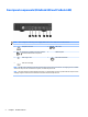
Front panel components (EliteDesk 800 and ProDesk 600) NOTE: Your computer model may look slightly different from the illustration in this section. 1 Headphone Connector 5 USB 3.0 Port 2 Microphone or Headphone Connector (software selectable, default mode is microphone) 6 HDD Activity LED 3 USB 3.0 Type C Port 7 Dual-State Power Button 4 USB 3.0 Port–Charging NOTE: The USB 3.0 Port–Charging also provides current to charge a device such as a Smart Phone.
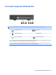
Front panel components (EliteDesk 705) NOTE: Your computer model may look slightly different from the illustration in this section. 1 Headphone Connector 4 USB 3.0 Port 2 Microphone Connector 5 HDD Activity LED 3 USB 3.0 Port–Charging 6 Dual-State Power Button NOTE: The USB 3.0 Port–Charging also provides current to charge a device such as a Smart Phone. The charging current is available whenever the AC power cord is connected to the system, even when the system is off.
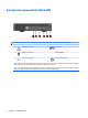
Front panel components (ProDesk 400) NOTE: Your computer model may look slightly different from the illustration in this section. 1 Headphone Connector 4 USB 3.0 Port 2 Microphone Connector 5 HDD Activity LED 3 USB 3.0 Port–Charging 6 Dual-State Power Button NOTE: The USB 3.0 Port–Charging also provides current to charge a device such as a Smart Phone. The charging current is available whenever the AC power cord is connected to the system, even when the system is off.
Rear panel components (EliteDesk 800, EliteDesk 705, and ProDesk 600) NOTE: Your computer model may look slightly different from the illustration in this section. 1 External Antenna Connector 8 VGA Monitor Connector 2 Thumbscrew 9 DisplayPort (default, shown), HDMI, or Serial Connector 3 Padlock Loop 10 USB 3.0 Ports (2) (blue) 4 Cable Lock Slot 11 USB 2.
Rear panel components (ProDesk 400) NOTE: 6 Your computer model may look slightly different from the illustration in this section. 1 External Antenna Connector 8 VGA Monitor Connector 2 Thumbscrew 9 Serial Port 3 Padlock Loop 10 USB 3.0 Ports (2) (blue) 4 Cable Lock Slot 11 USB 2.
Serial number location Each computer has a unique serial number and a product ID number that are located on the exterior of the computer. Keep these numbers available for use when contacting customer service for assistance.
2 Hardware upgrades Serviceability features The computer includes features that make it easy to upgrade and service. No tools are needed for most of the installation procedures described in this chapter. Warnings and cautions Before performing upgrades be sure to carefully read all of the applicable instructions, cautions, and warnings in this guide.
Connecting the AC power cord When connecting the AC adapter, it is important to follow the steps below to ensure the power cord does not pull free from the computer. 1. Connect the female end of the AC power cord to the AC adapter (1). 2. Plug the other end of the AC power cord into an AC outlet (2). 3. Connect the round end of the AC adapter cord to the power connector on the rear of the computer (3). 4.
Removing the computer access panel To access internal components, you must remove the access panel: 1. Remove/disengage any security devices that prohibit opening the computer. 2. Remove all removable media, such as a USB flash drive, from the computer. 3. Turn off the computer properly through the operating system, then turn off any external devices. 4. Disconnect the AC power cord from the AC outlet and disconnect any external devices.
Replacing the computer access panel 1. Place the panel on the computer and slide it back (1). 2. Tighten the thumbscrew (2) to secure the panel in place. NOTE: Your computer model may look slightly different from the illustration in this section.
Changing from desktop to tower configuration The computer can be used in a tower orientation with an optional tower stand that can be purchased from HP. 1. Remove/disengage any security devices that prohibit opening the computer. 2. Remove all removable media, such as a USB flash drive, from the computer. 3. Turn off the computer properly through the operating system, then turn off any external devices. 4. Disconnect the AC power cord from the AC outlet and disconnect any external devices.
Installing additional memory The computer comes with small outline, dual inline memory modules (SODIMMs). SODIMMs The memory sockets on the system board can be populated with up to two industry-standard SODIMMs. These memory sockets are populated with at least one preinstalled SODIMM. To achieve the maximum memory support, you can populate the system board with up to 32 GB (EliteDesk 800 and ProDesk 600) or 16 GB (EliteDesk 705 and ProDesk 400) of memory.
Populating SODIMM sockets There are two SODIMM sockets on the system board, with one socket per channel. The sockets are labeled DIMM1 and DIMM3. The DIMM1 socket operates in memory channel B. The DIMM3 socket operates in memory channel A.
Installing SODIMMs CAUTION: You must disconnect the AC power cord and wait approximately 30 seconds for the power to drain before adding or removing memory modules. Regardless of the power-on state, voltage is always supplied to the memory modules as long as the computer is plugged into an active AC outlet. Adding or removing memory modules while voltage is present may cause irreparable damage to the memory modules or system board. The memory module sockets have gold-plated metal contacts.
Item Description System Board Label Socket Color 1 SODIMM1 socket, Channel B DIMM1 Black 2 SODIMM3 socket, Channel A DIMM3 Black 10. To remove a SODIMM, press outward on the two latches on each side of the SODIMM (1) then pull the SODIMM out of the socket (2).
11. Slide the new SODIMM into the socket at approximately a 30° angle (1) then press the SODIMM down (2) so that the latches lock it in place. NOTE: A memory module can be installed in only one way. Match the notch on the module with the tab on the memory socket. 12. Connect the fan plug to the system board (1). 13. Set the fan into place and press it down to engage the latches (2). 14. Replace the access panel. 15. If the computer was on a stand, replace the stand. 16.
Removing and replacing a hard disk drive (HDD) NOTE: Before you remove the old HDD, be sure to back up the data from the old HDD so that you can transfer the data to the new HDD. 1. Remove/disengage any security devices that prohibit opening the computer. 2. Remove all removable media, such as a USB flash drive, from the computer. 3. Turn off the computer properly through the operating system, then turn off any external devices. 4.
9. To install a HDD, you must transfer the silver and blue isolation mounting guide screws from the old HDD to the new HDD. 10. Align the guide screws with the slots on the chassis drive cage, press the HDD down into the cage, then slide it forward until it stops and locks in place (1). 11. Connect the HDD power and data cable (2) to the HDD. 12. Replace the access panel. 13. If the computer was on a stand, replace the stand. 14. Plug in the AC power cord and turn on the computer. 15.
Replacing an M.2 PCIe solid state drive (SSD) 1. Remove/disengage any security devices that prohibit opening the computer. 2. Remove all removable media, such as a USB flash drive, from the computer. 3. Turn off the computer properly through the operating system, then turn off any external devices. 4. Disconnect the AC power cord from the AC outlet and disconnect any external devices.
c. Lift the fan out of the chassis (3). 11. Remove the three screws securing the HDD cage to the chassis (1). 12. Pull the hood sensor up and off the HDD cage (2). 13. Lift the HDD cage out of the chassis (3). Replacing an M.
14. Locate the SSD on the system board. 15. Remove the screw securing the SSD to the system board. 16. Grasp the SSD by the sides and carefully pull it out of the socket. 17. Insert the new SSD into the socket on the system board. NOTE: An SSD can be installed in only one way. 18. Press the SSD connectors firmly into the socket. 19. Press the SSD down to the system board and use the included screw to secure the SSD. 20. Set the HDD cage into the chassis (1). 21.
22. Secure the HDD cage to the chassis with the three screws (3). 23. If your model is an EliteDesk 800, replace the secondary fan under the HDD. a. Set the fan in place in the HDD cage (1). b. Fasten the two screws to secure the fan to the chassis (2). c. Connect the fan plug to the system board (3). 24. Align the HDD guide screws with the slots on the HDD drive cage, press the HDD down into the cage, then slide it forward until it stops and locks in place (1). Replacing an M.
25. Connect the HDD power and data cable (2) to the HDD. 26. Replace the access panel. 27. If the computer was on a stand, replace the stand. 28. Plug in the AC power cord and turn on the computer. 29. Lock any security devices that were disengaged when the computer cover or access panel was removed.
Replacing the WLAN module 1. Remove/disengage any security devices that prohibit opening the computer. 2. Remove all removable media, such as a USB flash drive, from the computer. 3. Turn off the computer properly through the operating system, then turn off any external devices. 4. Disconnect the AC power cord from the AC outlet and disconnect any external devices.
c. Lift the fan out of the chassis (3). 11. Remove the three screws securing the HDD cage to the chassis (1). 12. Pull the hood sensor up and off the HDD cage (2). 13. Lift the HDD cage out of the chassis (3).
14. Locate the WLAN module on the system board. 15. Disconnect both antenna cables from the WLAN module. NOTE: You may need to use a small tool, such as tweezers or needle-nose pliers, to disconnect and connect the antenna cables. 16. Grasp the WLAN module by the sides and pull it out of the socket. 17. Insert the new WLAN module into the socket on the system board. NOTE: A WLAN module can be installed in only one way. 18. Press the WLAN connectors firmly into the socket (1). 19.
23. Secure the HDD cage to the chassis with the three screws (3). 24. If your model is an EliteDesk 800, replace the secondary fan under the HDD. a. Set the fan in place in the HDD cage (1). b. Fasten the two screws to secure the fan to the chassis (2). c. Connect the fan plug to the system board (3). 25. Align the HDD guide screws with the slots on the HDD drive cage, press the HDD down into the cage, then slide it forward until it stops and locks in place (1).
26. Connect the HDD power and data cable (2) to the HDD. 27. Replace the access panel. 28. If the computer was on a stand, replace the stand. 29. Plug in the AC power cord and turn on the computer. 30. Lock any security devices that were disengaged when the computer cover or access panel was removed.
Installing an external antenna Internal WLAN antennae are standard on all HP G2 Desktop Mini models. If the computer is to be installed in a metal kiosk or other enclosure, you may wish or need to use an external WLAN antenna. 1. Remove/disengage any security devices that prohibit opening the computer. 2. Remove all removable media, such as a USB flash drive, from the computer. 3. Turn off the computer properly through the operating system, then turn off any external devices. 4.
c. Lift the fan out of the chassis (3). 11. Remove the three screws securing the HDD cage to the chassis (1). 12. Pull the hood sensor up and off the HDD cage (2). 13. Lift the HDD cage out of the chassis (3).
14. Locate the WLAN module on the system board. 15. Disconnect the internal antennae from the WLAN module. For instructions, see Replacing the WLAN module on page 25. 16. Locate both external antenna positions on the rear panel. 17. Insert a Phillips screwdriver in each knock-out feature and rotate to remove the blank.
18. Feed the external antenna cable through each hole and screw the antenna into position. 19. Connect the external antenna cables to the WLAN module. 20. Set the HDD cage into the chassis (1). 21. Press the hood sensor firmly into place (2). 22. Secure the HDD cage to the chassis with the three screws (3). 23. If your model is an EliteDesk 800, replace the secondary fan under the HDD. a. Set the fan in place in the HDD cage (1). b. Fasten the two screws to secure the fan to the chassis (2).
c. Connect the fan plug to the system board (3). 24. Align the HDD guide screws with the slots on the HDD drive cage, press the HDD down into the cage, then slide it forward until it stops and locks in place (1). 25. Connect the HDD power and data cable (2) to the HDD. 26. Replace the access panel. 27. If the computer was on a stand, replace the stand. 28. Plug in the AC power cord and turn on the computer. 29.
Replacing the battery The battery that comes with the computer provides power to the real-time clock. When replacing the battery, use a battery equivalent to the battery originally installed in the computer. The computer comes with a 3-volt lithium coin cell battery. WARNING! The computer contains an internal lithium manganese dioxide battery. There is a risk of fire and burns if the battery is not handled properly. To reduce the risk of personal injury: Do not attempt to recharge the battery.
9. Slide the drive back until it stops, then lift the drive up and out of the cage (3). 10. If your model is an EliteDesk 800, remove the secondary fan under the HDD. a. Disconnect the fan plug from the system board (1). b. Remove the two screws securing the secondary fan (2). c. Lift the fan out of the chassis (3). 11. Remove the three screws securing the HDD cage to the chassis (1). 12. Pull the hood sensor up and off the HDD cage (2).
13. Lift the HDD cage out of the chassis (3). 14. Locate the battery and battery holder on the system board. NOTE: You may need to use a small tool, such as tweezers or needle-nose pliers, to remove and replace the battery. 15. Lift the battery out of the holder.
16. Slide the replacement battery into position, positive side up. The battery holder automatically secures the battery in the proper position. 17. Set the HDD cage into the chassis (1). 18. Press the hood sensor firmly into place (2). 19. Secure the HDD cage to the chassis with the three screws (3). 20. If your model is an EliteDesk 800, replace the secondary fan under the HDD. a. Set the fan in place in the HDD cage (1). b. Fasten the two screws to secure the fan to the chassis (2). c.
22. Connect the HDD power and data cable (2) to the HDD. 23. Replace the computer access panel. 24. If the computer was on a stand, replace the stand. 25. Plug in the AC power cord and turn on the computer. 26. Lock any security devices that were disengaged when the computer access panel was removed. 27. Reset the date and time, your passwords, and any special system setups using Computer Setup. Installing a security lock The cable lock and padlock displayed below can be used to secure the computer.
Attaching the computer to a mounting fixture The computer can be attached to a wall, swing arm, or other mounting fixture. NOTE: This apparatus is intended to be supported by UL or CSA Listed wall mount bracket. 1. If the computer is on a stand, remove the computer from the stand and lay the computer down. 2. To attach the computer to a swing arm (sold separately), insert four screws through the holes on the swing arm plate and into the mounting holes on the computer.
Synchronizing the optional wireless keyboard and mouse The mouse and keyboard are synchronized at the factory. If they do not work, remove and replace the batteries. If the mouse and keyboard are still not synchronized, then follow this procedure to manually resynchronize the pair. 1. 2. 3.
4. 5. NOTE: If the mouse and keyboard still do not work, then remove and replace the batteries. If the mouse and keyboard are still not synchronized, then synchronize the keyboard and mouse again.
A Electrostatic discharge A discharge of static electricity from a finger or other conductor may damage system boards or other staticsensitive devices. This type of damage may reduce the life expectancy of the device. Preventing electrostatic damage To prevent electrostatic damage, observe the following precautions: ● Avoid hand contact by transporting and storing products in static-safe containers. ● Keep electrostatic-sensitive parts in their containers until they arrive at static-free workstations.
B Computer operating guidelines, routine care and shipping preparation Computer operating guidelines and routine care Follow these guidelines to properly set up and care for the computer and monitor: 44 ● Keep the computer away from excessive moisture, direct sunlight, and extremes of heat and cold. ● Operate the computer on a sturdy, level surface. Leave a 10.2 cm (4 inch) clearance on all vented sides of the computer and above the monitor to permit the required airflow.
Shipping preparation Follow these suggestions when preparing to ship the computer: 1. Back up the HDD files to an external storage device. Be sure that the backup media is not exposed to electrical or magnetic impulses while stored or in transit. NOTE: The HDD locks automatically when the system power is turned off. 2. Remove and store all removable media. 3. Turn off the computer and external devices. 4. Disconnect the AC power cord from the AC outlet, then from the computer. 5.
Index A access panel removal 10 replacement 11 B battery replacement solid state drive 20 WLAN module 25 K keyboard synchronizing wireless 41 35 C computer operating guidelines 44 E electrostatic discharge, preventing damage 43 external antenna installation 30 F front panel components EliteDesk 705 3 EliteDesk 800 2 ProDesk 400 4 ProDesk 600 2 H hard disk drive installation 18 removal 18 I installation guidelines 8 installing battery 35 computer access panel 11 external antenna 30 hard disk drive 18 l