HP Vectra VE 5/xx Series 2 User's Guide
NOTICE Information contained in this document is subject to change without notice. Hewlett-Packard makes no warranty of any kind with regard to this material, including, but not limited to, the implied warranties of merchantability and fitness for a particular purpose. Hewlett-Packard shall not be liable for errors contained herein or for incidental or consequential damages in connection with the furnishing, performance, or use of this material.
Table of Contents NOTICE WELCOME TO YOUR HP VECTRA PC 1 SETTING UP YOUR PC 9 UNPACKING YOUR PC CONNECTING THE MOUSE, KEYBOARD, AND DISPLAY CONNECTING A PRINTER CONNECTING THE POWER CORDS STARTING THE PC FOR THE FIRST TIME CREATING MASTER DISKETTES 2 USING YOUR PC 4 8 9 11 11 12 13 16 17 STARTING AND STOPPING YOUR PC STARTING YOUR PC STOPPING YOUR PC THE HP VECTRA KEYBOARD ADVANCED POWER MANAGEMENT HP USER TOOLS DESKTOP MANAGEMENT INTERFACE 17 17 18 18 19 19 19 3 HOW TO INSTALL ACCESSORIES IN YOUR
INSTALLING AN UPGRADE PROCESSOR INSTALLING THE SECURITY BRACKET 4 THE HP SETUP PROGRAM 49 50 52 USING THE HP SETUP PROGRAM STARTING THE SETUP PROGRAM UNDERSTANDING THE SETUP PROGRAM SETTING PASSWORDS SETTING PASSWORDS AFTER INSTALLING AN IDE DRIVE IF YOU LOSE THE KEY 5 TROUBLESHOOTING YOUR PC 63 SOLVING PROBLEMS IF YOUR PC DOES NOT START PROPERLY DISPLAY IS BLANK AND THERE ARE NO ERROR MESSAGES IF YOU ARE UNABLE TO CHANGE ANY VALUES IN SETUP IF A POST ERROR MESSAGE IS DISPLAYED IF YOUR PC HAS A HARDW
7 HEWLETT PACKARD SUPPORT AND INFORMATION SERVICES 84 INTRODUCTION YOUR HP AUTHORIZED RESELLER HP SUPPORTPACK HP SUPPORT ASSISTANT CD-ROM HEWLETT-PACKARD INFORMATION SERVICES HP FORUM ON COMPUSERVE HP FORUM ON AMERICA ONLINE HP BBS LIBRARY INTERNET—FTP LIBRARY SERVICE ACCESS HP WORLD WIDE WEB SITE HP FAXBACK ON DEMAND—HP FIRST HP AUDIO TIPS (USA ONLY) HP AUTOMATED SUPPORT DIRECTORY ORDERING DRIVERS AND BIOS ON DISKETTE HP SUPPORT SERVICES HEWLETT-PACKARD TELEPHONE SUPPORT LIFELINE TELEPHONE SUPPORT HP NETWO
WELCOME TO YOUR HP VECTRA PC Congratulations on the purchase of your new Hewlett-Packard desktop PC.
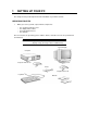
1 SETTING UP YOUR PC This chapter leads you through the first time installation of your HP Vectra PC. UNPACKING YOUR PC 1 When you receive your PC, unpack all the components: • • • • the computer and power cord the display and its cables the keyboard and mouse the manuals. On some models, the operating system software, drivers, and HP User Tools are preloaded on the hard disk. WARNING: If you have any doubt that you can lift the PC or display safely, do not try to move it without help.
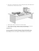
2 Place the PC on a sturdy desk near to easily accessible power outlets, with enough space for the keyboard, mouse, and any other accessories. 3 Position the PC so that its rear connectors are easily accessible. 4 Place the display on top of the computer. If you have a large display, place it next to the computer. Refer to the display’s manual for information about the display. Installation Tools No tools are required to set up your PC.
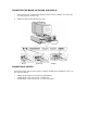
CONNECTING THE MOUSE, KEYBOARD, AND DISPLAY 1 Connect the mouse, keyboard, and display to the back of the computer. The connectors are shaped to go in one way only. 2 Tighten the display cable attachment screws. Mouse Keyboard Display CONNECTING A PRINTER Connect the printer cable to the back of the computer and tighten the attachment screws.
Parallel Connector Serial Connector CONNECTING THE POWER CORDS 1 If fitted, remove the label covering the computer’s power connector. 2 Connect the power cords to the display and the computer. 3 Connect the display’s power cord and the computer’s power cord to a grounded outlet. (The connectors are shaped to go in one way only.
Display Power Cord Computer Power Cord Grounded Outlet WARNING: For your safety, always connect the equipment to a grounded wall outlet. Always use a power cord with a properly grounded plug, such as the one provided with this equipment, or one in compliance with your national regulations. This PC is disconnected from the power by removing the power cord from the power outlet. This means the PC must be located close to a power outlet that is easily accessible.
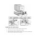
To initialize your software 1 Switch on the display first, and then the PC (this will allow your PC to recognize the type of display you have). Switch on the Display Then switch on the PC NOTE Do NOT switch OFF the PC while the software is being initialized for the first time as this could cause unexpected results. When the PC is switched on, the Vectra Logo is displayed. The PC performs a Power-OnSelf-Test (POST). Press [ESC] if you want to view the POST information.
3 • The model number of your display. The display’s model number is shown on the cover of the manual supplied with the display and on a label on the rear of the display. • You may also be asked to select which operating system you want to use, Windows 3.11 or Windows 95. Once you have confirmed your selection of the operating system, you cannot change that selection.
CREATING MASTER DISKETTES NOTE It is very important that you create master diskettes for your preloaded software as soon as possible.These diskettes will be your unique means of regenerating your system if you need to restore the preloaded software onto your PC. Use new diskettes to create master diskettes. Windows 3.11 Choose this utility in the HP User Tools group in Program Manager and follow the screen messages, which will tell you how many diskettes you need.
2 USING YOUR PC This chapter explains how to use the HP Vectra PC to increase your productivity. STARTING AND STOPPING YOUR PC STARTING YOUR PC 1 Before you start your PC, always switch on the display first. 2 Start your PC in one of these ways: • • press the power button on the front panel press the space bar. When you switch on the computer, the computer carries out the Power-On-Self-Test (POST) while the Vectra logo is displayed. If you wish to view the POST details, press [ESC].
STOPPING YOUR PC Stopping the PC when using Windows 3.11 To stop the PC, make sure that you have exited all programs and then exited Windows before pressing the power button on the control panel. Stopping the PC when using Windows 95 To stop or shut down the PC: 1 2 3 Click on Start. Click on Shut Down. Click on Shut down the computer. You can return the PC to full power mode by pressing the space bar.
The Application Key The Application key allows you to access all the same functions as the right mouse button. It can be used to copy and move files, to access shortcut menus and get Help information. The Application key can also be programmed by your software. The Power-On Icon on the Space Bar The Power-On function enables you to start your PC by pressing the space bar. This function is not specific to Windows 95, but is available whatever your operating system.
3 HOW TO INSTALL ACCESSORIES IN YOUR PC This chapter explains how to install accessories, such as extra memory, accessory boards, and additional disk drives, in your PC. SUPPORTED HP ACCESSORIES This chapter describes how to install memory, mass storage devices, and accessory boards in your PC. Refer to "Hewlett Packard Support and Information Services" (chapter 7) for information about how to obtain an up-to-date list of supported devices. One internal mass storage device 630 MB IDE, order D2929A or 1.
1 MB Video Memory Upgrade Up to four accessory boards Top two: PCI Bottom three: ISA Processor Processor Voltage Shorting Block Main Memory Modules (32-bit EDO, 60 ns) 8 MB kit (2 x 4 MB modules) order D3646A 16 MB kit (2 x 8 MB modules) order D3647A 32 MB kit (2 x 16 MB jmodules) order D3648A 256 KB Level 2 Cache Memory (optional) Order D3659A WARNING: For your safety, never remove the PC’s cover without first removing the power cord from the power outlet, and any connection to a telecommunications
REMOVING THE COVER 1 Switch off the display and the PC. 2 Disconnect the power cords from the power outlets, the PC, and the display. Disconnect any connection to a telecommunications network. Then remove the display. 3 If necessary, unlock the cover using the key provided with the PC. 4 Slide the two tabs on the front of the computer inwards. Firmly slide the cover forward 5 cm (2 inches), and lift it up and off the computer.
REPLACING THE COVER AFTER INSTALLING ACCESSORIES 1 Check that you have installed all your accessories. 2 Make sure that all internal cables are properly connected and safely routed so they will not be entangled when you replace the cover. 3 Ensure the cover lock is unlocked and the tabs are inwards. 4 Lower the cover onto the computer, and firmly slide it into position. 5 Slide the two tabs on the front of the cover outwards. 6 If a keylock is fitted, lock the cover using the key.
3 Lift the front of the power supply to disengage the hinge on the rear. 4 Lift the power supply clear and lay it upside down on the frame above the disk drives. REPLACING THE POWER SUPPLY AFTER INSTALLING ACCESSORIES 1 Ensure that you have installed all your accessories in the PC. 2 Replace the power supply on the left-hand side of the PC, and ensure that the cables are neatly routed around any accessory boards.
3 Raise the front of the power supply and engage the hinge on the rear. 4 Lower the front of the power supply into position so that it rests on the front panel. INSTALLING MEMORY MAIN MEMORY MODULES Your PC is supplied with main memory. If you need more main memory to run your application software, you can install up to a total of 128 MB. Main memory is available in modules of 4 MB, 8 MB, 16 MB, or 32 MB. You must install identical modules in pairs in each bank.
4 Pivot the memory module to the vertical position and click into place. 5 Repeat this procedure for each memory module you are installing.If you need to remove a main memory module: Release the retaining clip and pull the module forward and out of the socket 6 Install any other accessories before replacing the cover and power supply. Reconnect all cables and power cords.
INSTALLING AN OPTIONAL CACHE MEMORY MODULE You can install a 256 KB level 2 cache memory module. Order HP D3659A. CAUTION: Static electricity can damage electronic components. Turn all equipment OFF. Don’t let your clothes touch the accessory.To equalize the static electricity, rest the accessory bag on top of the power supply while you are removing the accessory from the bag. Handle the accessory as little as possible and with care.
INSTALLING A VIDEO MEMORY UPGRADE Your PC is supplied with 1 MB of video memory on the system board. If you want better performance, higher resolutions or more colors, you can install a pair of video memory modules to increase your available video memory to 2 MB. Detailed information about available video resolutions is given in chapter 5, Technical Information. CAUTION: Static electricity can damage electronic components. Turn all equipment OFF. Don’t let your clothes touch the accessory.
After Installing a Video Memory Upgrade 1 Switch on the PC. 2 Select HP User Tools. 3 Click on the Video Mode button and follow the screen messages. You may be asked to insert a diskette containing an appropriate video driver in drive A. For the latest available version of a required driver, refer to the "HP BBS Library" in chapter 7.
The ICU is preloaded with configuration details for many non-Plug and Play accessory boards. If your accessory board is not listed by the ICU, you have two options: a Some non-Plug and Play accessory boards are supplied with a configuration file, which can be used by the ICU to determine which resources are required by the board. Insert the disk containing the configuration file when prompted by the ICU.
4 Unscrew and remove the slot cover. Store it in a safe place. If the slot cover is tight, loosen the screws on the adjacent slots. 5 Hold the board horizontally by its “top” edge. Slide it into the board guide of the chosen slot. Do not bend the board. 6 Align the board’s connector with the slot’s socket and firmly press into the socket. Ensure the board’s connector engages completely with the socket and does not touch components on other boards.
7 Secure the board by replacing the slot cover screw. If you loosened the screws on adjacent slots, tighten them. 8 If you install a VESA-standard video adapter board which uses the integrated video graphics controller, connect the accessory board’s cable to the VESA pass-through connector on the system board. 9 Install any other accessories before replacing the power supply and the cover. Reconnect all cables and power cords.
INSTALLING MASS STORAGE DEVICES You can install additional mass storage devices, if you need extra mass storage space for your application software. The PC has one internal drive shelf for a hard disk drive. If your PC already has a hard disk drive, this shelf will be occupied. There are three front access drive shelves. The top shelf is occupied by a 3.5-inch flexible disk drive. The middle shelf can be used to install a 5.25-inch flexible disk drive or a CD-ROM drive.
Up to three IDE devices can be connected to the system board using these data cables.(Refer to the storage device’s manual to check whether you need to set jumpers, or if there are any special installation procedures.
Before Installing an Additional IDE Drive Create a bootable diskette before installing an additional IDE drive. Refer to the operating system documentation for information on how to create a bootable diskette, format a drive, and install the operating system. Examples of multiple IDE drive combinations Configuration Connections to data cables 1 Hard disk drive 1. Bootable hard disk drive: Master connector, HDD data cable 2 Hard disk drives 1.
3 Remove the bezel from the middle shelf. The bezel snaps in and out, and can be removed without any tools. Put it in a safe place in case you remove the drive at a later time and need to cover this shelf. 4 Slide the device into the middle shelf using mounting rails, and secure the device in position using the screws provided.
5 Connect the data and power cables to the rear of the device installed in the middle shelf. The connectors are shaped to go in one way only. If you are installing an IDE CD-ROM drive, connect the drive to the CD-ROM data cable. This data cable should be connected to the connector marked “CD-ROM” on the system board. If you are not sure which connector to use, refer to "Connecting IDE Devices" earlier in this chapter. 6 Install any other accessories before replacing the cover.
INSTALLING AN IDE HARD DISK DRIVE IN THE REAR SHELF The PC has an integrated Enhanced IDE controller which supports two Fast IDE hard disk drives. Refer to the drive’s manuals to see if you must set jumpers or if there is a special installation procedure to follow. 1 Disconnect the computer’s power supply cord and any connection to a telecommunications network. 2 Remove the computer’s cover. 3 Slide the drive into the rear drive shelf, supporting the drive with your hand.
4 Align the drive with the holes in the rear drive shelf. Then secure the drive with the screws provided with it. 5 Connect the power cable and the data cable to the rear of the drive. The connectors are shaped to go in one way only. 6 Install any other accessories before replacing the cover. Reconnect all cables and power cords.
INSTALLING AN IDE HARD DISK DRIVE IN THE BOTTOM SHELF The PC has an integrated Enhanced IDE controller which supports two Fast IDE hard disk drives. Refer to the drive’s manual to see if you must set jumpers or if there is a special installation procedure to follow. 1 Disconnect the computer’s power supply cord from the power outlet. Disconnect any connection to a telecommunications network. 2 Remove the computer’s cover. 3 If there is a device in the middle shelf, remove it.
6 Support the power supply with your hand (to prevent it falling out) and carefully turn the PC onto its side. 7 Slide the hard disk into the bottom shelf, supporting the disk with your hand.
8 Align the drive with the holes in the bottom of the PC. Support the drive with your hand while securing the drive with the four screws provided. 9 Support the power supply with your hand and very carefully return the PC to the upright position. 10 Connect the data and power cables to the rear of the drive. The connectors are shaped to fit one way only. If you are not sure which connector to use, refer to "Connecting IDE Devices" earlier in this chapter.
13 Install any other accessories before replacing the cover. Replace the side bezel. Reconnect all cables and power cords. INSTALLING A 5.25-INCH DISK DRIVE IN THE BOTTOM SHELF A slim (1-inch high) 5.25-inch front access drive can be installed in the bottom shelf. NOTE Disk drives ordered from HP are supplied with mounting rails. If you order your drive from another supplier, you will need to order drive mounting rails from HP (refer to "Supported HP Accessories", in chapter 1.
5 Remove the two bezels from the bottom shelf. 6 Remove the side bracket from the bottom shelf and store it in a safe place.
7 Slide the drive mid-way into the bottom shelf. 8 Connect the data and power cables to the rear of the drive.
9 Slide the drive completely into the bottom shelf and secure it with the screws provided with the device. 10 If a device was removed from the middle shelf, replace it. 11 If no device was removed from the middle shelf, replace the bezel. 12 Install any other accessories before replacing the cover. Reconnect all cables and power cords. INSTALLING A 3.5-INCH DISK DRIVE IN THE BOTTOM SHELF A slim (1-inch high) 5.25-inch front access drive can be installed in the bottom shelf.
4 If there is no device in the middle shelf, remove the bezel. The bezel snaps in and out, and can be removed without any tools. 5 Remove the two bezels from the bottom shelf.
6 Slide the drive completely into the bottom shelf and secure it with the screws provided with the device. 7 Replace the side bezel.
8 Connect the data and power cables to the rear of the drive. The connectors are shaped to fit one way only. Power Cable Data Cable 9 If a device was removed from the middle shelf, replace it. 10 If no device was removed from the middle shelf, replace the bezel. 11 Install any other accessories before replacing the cover. Reconnect all cables and power cords.
4 Raise the lever on the socket to unlock the processor and lift out the processor. Heat Sink Processor 5 To install the new processor: a b c d e Locate the corner markers: • on the processor—a dot or notch (“broken” corner) • on the processor socket—a dot. Position the processor over the socket, with it’s corner marker facing the corner marker on the socket. Place the processor into the socket. Lower the lever to lock the processor into place.
2 Remove the security bracket from the storage position. Remove the bracket from the storage position Insert the bracket in the computer 3 Insert the security bracket, from inside the computer, into the slot shown in the diagram above. 4 Press it firmly until it snaps into place. 5 Install any other accessories before replacing the cover.
4 THE HP SETUP PROGRAM This chapter describes how to use the HP Setup program. USING THE HP SETUP PROGRAM Setup is an integrated (ROM-based) program that displays the PC’s configuration and allows you to set parameters. Check the configuration when you first use the PC and each time after you install, remove, or upgrade accessories. If an error message is displayed, see chapter 5, Troubleshooting Your PC.
2 Press [F2] while F2=Setup is displayed at the bottom of the screen. F2=Setup appears for a short period, during the POST (Power-On-Self-Test). NOTE 3 If you fail to press [F2] in time and the start-up process continues, you will need to restart your PC to go through the POST again so you can press [F2]. The PC’s Setup program will display. PhoenixBIOS Setup Copyright 1985-95 Phoenix Technologies Ltd. Copyright 1995 Hewlett-Packard Rev. GW.O5.
• [ESC] or [ALT] + [X] allows you to exit from a sub-menu. • The ← and → arrows select menus from the menu bar. • [F9] loads factory-installed default values. • [F10] restores previous values from CMOS. • [F1] or [ALT] + H displays the general help screen. • [ESC] exits from the general help screen. • Use the [F12] key to exit Setup without saving any changes. • Use the [F3] key to save your settings and exit Setup.
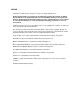
Setup Items Defaults Main System Time System Date Action Allows you to set the system time and date. Select the field you want to change with Tab, shift Tab, or Enter. System memory Extended memory 640 KB 15MB* Allows you to view the system memory and extended memory. Value is typical value, real value depends on your configuration. Running Windows 95 [No] Allows you to enable/disable Windows 95.
Setup Item Default* Action Parallel port 378h IRQ7 Enables or disables the on-board parallel port at the specified address. ‘Disabled’ frees resources used by the port. Parallel port node Centronics™ Serial port A 3F8h IRQ4 Serial port B 2F8h IRQ3 Flexible disk controller Enabled Flexible disk drive A Flexible disk drive B A & B flexible disk swap 1.44 MB, 3½“ Not Installed Disabled Sets the operating mode of the parallel port. Other options are: B-Directional; ECP DMA1; or ECP DMA3.
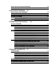
Setup Item Default* Action Memory and Cache Memory caching Both Controls internal (L1) and external (L2) memory caching. Memory hole Disabled Shadow/Cache ISA Option ROMs Disabled Sets a 1 MB memory hole between 15 MB and 16 MB if needed. You need at least 16 MB for this option to be available. Enables shadowing and caching for ISA "Non PnP" Option ROMs for region X-Y, in order to improve performance. Note that some Option ROMs cannot be shadowed.
PC I Devices Slot #1 Bus Master Slot #2 Bus Master Enabled Enabled Slot #3 Bus Master Enabled PCI IRQ line 1 PCI IRQ line 2 Auto Auto PCI IRQ line 3 PCI IRQ line 4 Auto Auto Setup Item Default* Action Disabled Indicates whether administrator password is enabled. Allows you to set the administrator password. This password prevents unauthorized access to the PC’s configuration and can also be used to start the PC. Enable or disable password prompt on boot.
Setup Item Default* Action Standby Delay 30 minutes Sets the period of inactivity before the system runs in Standby mode. Standby mode slows down the processor. The delay is an approximate time, depending on the CPU speed. Standby Wakeup Mouse PS2/IRQ12 Enabled Enables or disables the system to return to full speed when the mouse is moved. IRQ3 (Serial Port) Enabled Enables or disables the system to return to full speed when an IRQ is generated.
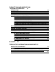
F2=Setup 3. The PC's Setup program will display. Setting an Administrator Password • Use the ← or → key to select the Security menu item. • Use the ↑ or ↓ arrow keys to highlight the Set Administrator Password field. • Type the password twice and press [ENTER]. 4 If you do not set an Administrator password you cannot set a user password. 5 If that is all you want to change in Setup, press [F3] to save your password and exit Setup.
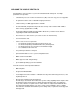
AFTER INSTALLING AN IDE DRIVE After installing a second IDE drive you will need to run the Setup program to confirm that the drive has been detected by the PC. When an Additional IDE Drive is installed 1 Switch on the PC. 2 When F2=Setup is displayed, press [F2] to run the Setup program. 3 From the “Configuration” menu, choose “Hard disk drive”. 4 Select the disk you have just installed. 5 Select Auto in the Type field. 6 Select Autotype fixed disk and press [ENTER].
IF YOU LOSE THE KEY If you lose the key to the PC, you need to order a replacement lock (HP part number 50625590) from the HP dealer or HP Sales and Service Office. The new lock is delivered with two keys. Contact your HP dealer for installing the new lock.
5 TROUBLESHOOTING YOUR PC This chapter can help you solve problems that you may encounter when using your PC. SOLVING PROBLEMS This chapter can help you solve most problems you might have with your PC. If you are unable to solve your problem after following the advice in this chapter, refer to chapter 7, Hewlett Packard Support and Information Services.
Check Internal Items If the PC still does not start properly, follow this procedure to check the internal items: 1 Turn off the display, the computer, and all external devices. 2 Unplug all power cords and cables, noting their positions. Disconnect the PC from any telecommunications network. 3 Remove the cover. 4 Check the following items: Action Reference Check all internal cables. Ensure they are correctly attached and firmly in place. Check that the processor is correctly installed.
4 Check the system board switches. Refer to “System Board Connectors and Switches” in chapter 6. Be sure the Secure Switch is set to “open”. 5 Replace the cover. 6 Reconnect all cables and power cords. 7 Turn on the display and computer. IF A POST ERROR MESSAGE IS DISPLAYED If a POST error is detected when the PC starts, details of the error are displayed.
4 Run Setup by pressing [F2]. CMOS default values will be automatically downloaded and saved. 5 Make any other changes you want and press [F3] to save the configuration and exit from Setup. Power-On-Self-Test Errors that May Prevent Your PC From Starting Message Corrective Action and/or Explanation Operating system not found Check whether the disk, HDD, FDD or CD-ROM disk drive is connected.If it is connected, check that it is detected by Setup, “After Installing an IDE Drive” on page 71.
DISPLAY DOES NOT WORK PROPERLY If Nothing is Displayed on the Screen If nothing is displayed on the screen, but the PC starts and the keyboard, disk drives, and other peripheral devices seem to operate properly: • Make sure that the display is plugged in and switched ON. • Check that the brightness and contrast controls are properly set. • Ensure that the display video cable is correctly connected. • Switch off the display, and unplug it from the power outlet.
Windows 95 When you change the display type when using Windows 95, a confirmation box is displayed prompting you to confirm the selection. However, if you have selected the wrong display type and cannot read the screen message because the screen is blurred, the display type will automatically return to the previous selection after approximately 15 seconds. Other Display Problems If the display image is not aligned with the screen, use the display’s controls to center the image.
• Verify that you have the correct cable for the printer. Make sure that it is securely connected to the correct connector (port) on the PC and printer. • Check that the printer is online. • Examine the paper feed mechanism for a paper jam. • Make sure that the printer is configured correctly for the PC and for the application. a Ensure the PC’s port has been correctly configured using Setup. b Make sure the printer is correctly set up in your operating system’s configuration.
If the Hard Disk Activity Light Does Not Work If the hard disk activity light does not flicker when the PC is accessing the hard disk drive: • Check that the control panel connector is firmly attached to the system board. • Check that the disk power and data cables are correctly connected.
IF YOUR PC HAS A SOFTWARE PROBLEM If You Have Forgotten Your Password • • If you forget the User Password, but not the Administrator password, carry out the following procedure: 1 Restart the PC. If the keyboard is locked, unplug the power cord and plug it in again. 2 Wait for F2=Setup to be displayed. 3 Press [F2] to start Setup. 4 Enter the Administrator Password to access the Preferences menu. 5 Move to the User Password field and set a new User Password.
• If Windows does not run properly, refer to the Windows manual for guidance. IF POWER MANAGEMENT DOES NOT WORK Power Management in Windows 3.11 Check that the Sleep icon appears in the StartUp Windows group. If it is absent, click on the File menu in the Program Manager and select the New option to install SLEEP.EXE from the C:\WINDOWS directory in the StartUp group.
CHANGING THE BATTERY Special care is needed in changing the battery. Instructions for changing the battery are given below. You should order replacement battery HP 1420-0314 from your local Sales and Service office, or a Rayovac 2325/2335 or Mitsubishi BR2325/BR2335, either of which is available from most local stores. After removing the computer’s cover: 1 Remove the old battery by gently sliding it from under the retaining clip.
WARNING: There is a danger of explosion if the battery is incorrectly installed. For your safety, never attempt to recharge, disassemble, or burn the old battery. Replace the battery only with the same or equivalent type recommended by the manufacturer. The battery in this PC is a lithium battery which does not contain heavy metals, nevertheless, in order to protect the environment, do not dispose of batteries in household waste.
6 TECHNICAL INFORMATION This chapter provides technical information about your PC.
FEATURES Characteristics Description Weight (excluding keyboard and display) 9 kilograms (20 pounds) Dimensions 39 cm (D) by 42 cm (W) by 12.5 cm (H) (15.3 inches by 16.5 inches by 4.9 inches) Footprint 0.17m2 (1.
NOTE When the PC is turned off with the power button on the front panel, the power consumption falls below 5 Watts, but is not zero. The special on/off method used by this PC considerably extends the lifetime of the power supply. To reach zero power consumption in "off" mode, either unplug the PC from the power outlet or use a power block with a switch. You should be aware that the PC will lose its time settings within a few days if you unplug the PC, or switch off the PC at the power block.
NOTE When the PC is turned off with the power button on the front panel, the power consumption falls below 5 Watts, but is not zero. The special on/off method used by this PC considerably extends the lifetime of the power supply. To reach zero power consumption in "off" mode, either unplug the PC from the power outlet or use a power block with a switch. You should be aware that the PC will lose its time settings within a few days if you unplug the PC, or switch off the PC at the power block.
I/O Addressed used by PC 170h 1F0h 278h 2E8h 2F8h 370h 378h 3B0h 3E8h 3F0h 3F8h 496h 678h 778h 177h, 376h IDE secondary channel 1F7h, 3F6h IDE primary channel 27Fh parallel port 2EFh serial port 2FFh serial port 371h integrated I/O controller 37Fh parallel port 3DFh integrated video graphics controller 3EFh serial port 3F5h, 3F7h integrated flexible disk controller 3FFh serial port 497h HP reserved 67Bh parallel port if ECP mode is selected 77Bh parallel port if ECP mode is selected AVAILABLE VIDEO RESOL
Typical Windows 95 Video Resolutions Resolution 640 x 480 800 x 600 Number of colors 16, 256,64K, 16M 16, 256 Refresh Rate 60, 72, 75 56, 60, 72, 75 800 x 600 1024 x 768 64K 256 56, 60 43i, 60, 70, 75 640 x 480 800 x 600 16, 256, 64K, 16M 16, 256,64K, 16M 60, 72, 75 56, 60, 72, 75 1024 x 768 1280 x 1024 256, 32K, 64K 16, 256 43i, 60, 70, 75 43i, 60, 72, 75 Memory 1 MB 2 MB THE PC'S MEMORY MAP Memory Area Hexadecimal Address Range Used By 100000 upward Windows Applications 960 KB to 1024 K
THE PC'S REAR CONNECTORS Keyboard/Mouse Parallel Connector Serial Connector VGA Video Connector
SYSTEM BOARD CONNECTORS AND SWITCHES VESA Connector System Board Switches System Board Switches Switch Switch function: 1-4 Processor speed, see table on next page 5 Password: Open = enabled [default] Closed = disabled / clear passwords 6 CMOS: Open = normal [default] Closed = clear CMOS 7 Processor speed, see table on next page 8 Secure mode selection: Open = normal [default] Closed = Super secure mode (no BIOS flashing and no Setup changes allowed) 9 Keyboard (space bar) power on: Open = di
The settings for different processors at different speeds are a combination of the settings of switches 1, 2, 3, 4 and 7. Pentium processor Switch 1 Switch 2 Switch 3 Switch 4 Switch 7 CPU Frequency 75 MHz CPU bus Frequency 50 MHz Closed Closed Open Open Open Open Closed Open Open Closed Open Closed Closed Open Closed PCI Frequency 25 MHz AT Frequency 8.33 MHz CPU Frequency 100 MHz CPU bus Frequency 66 MHz PCI Frequency 33 MHz AT Frequency 8.
7 HEWLETT PACKARD SUPPORT AND INFORMATION SERVICES INTRODUCTION Hewlett Packard computers are engineered for quality and reliability to give you many years of trouble-free service.
HP SUPPORTPACK HP’s three-year SupportPack is available from your local reseller. It must be purchased within 30 days of purchasing your HP Vectra. The concept of SupportPack is simple. It allows you to extend your one-year on-site hardware warranty to a three-year on-site hardware warranty, offering next day on-site response. SupportPack is valid for the piece of equipment for which it was bought, but is not transferable from one piece of equipment to another.
As a preferred Hewlett Packard customer, you are invited to join CompuServe at no initial charge. For the United States and the United Kingdom, call the number shown below and ask for representative 51. For all other locations, first call the worldwide number to obtain the number of your local sales office, then call your local sales office and ask for representative 51.
INTERNET—FTP LIBRARY SERVICE Hewlett-Packard provides a library service which offers the latest versions of drivers, BIOS and utilities and other information about HP products. This library service is available if you have FTP access to the Internet, whatever your location. Alias Name ftp-boi.external.hp.
ORDERING DRIVERS AND BIOS ON DISKETTE You can order diskettes from HP, with the latest versions of drivers, BIOS and software utilities. The diskettes will be delivered by mail. Information for ordering diskettes is set out in the table below: North and Latin America Europe Phone +1 (970) 339 7009 Monday - Saturday 24 hours per day Phone +44 (1429) 865511 Monday - Friday 8.30 a.m. - 6.00 p.m.
Lifeline Telephone support is available during the second and third years of hardware warranty, via the Lifeline program, which is a fee-based service. The HP telephone support service does NOT provide free telephone support for PCs configured as network servers. If you do configure your PC as a network server, you are advised to contact your HP reseller to purchase a network phone-in support contract, which will provide you with a fee-based telephone support service.
LIFELINE TELEPHONE SUPPORT Lifeline is a fee-based telephone support program for Vectra PCs available after the one-year telephone support provided as part of the hardware warranty has expired. Your call can either be charged to your phone bill at a per minute rate or to your credit card (Visa, Mastercard or American Express) at a flat fee. The charge begins AFTER you have been put in contact with a support technician.
SUMMARY The table below summarizes the services and support available from HP or authorized resellers.
HEWLETT-PACKARD MARKETING HEADQUARTERS Should you wish to contact Hewlett-Packard, check your local telephone directory for the HP Sales and Service Office near you. If you cannot find a convenient HP office, you can write to one of the major HP Sales and Service Offices or one of the Worldwide Marketing Headquarters listed here. ASIA Far East Sales Region Hdqtrs Hewlett-Packard Asia Ltd. 22/F Peregrine Tower Lipp Centre 89 Queensway, Central Hong Kong LATIN AMERICA Hewlett-Packard Latin Am.
HP WORLD WIDE WEB SERVER Access the HP World Wide Web server for technical information, to download new drivers, utilities, and flash BIOS upgrades. Point your WWW browser at: http://www.hp.com HP ANONYMOUS FTP SERVER Access the HP Anonymous FTP server to download new drivers, utilities, and flash BIOS upgrades. FTP to IP address: xxx.x.xx.x EUROPEAN CUSTOMER SUPPORT CENTER For assistance from the HP European Customer Support Center, the number is: +00 000 0000.
GLOSSARY adapter An accessory board, that connects to the system board via an accessory board slot. BBS Bulletin Board System. A computer that uses a modem and software to serve as an information source for other computers equipped with a modem. Hewlett-Packard has a BBS that can be reached at +1 (408) 553-3500. BIOS Basic Input-Output System. Software that provides an interface between the computer hardware and the operating system. bus An electrical connection over which information is transported.
extended memory Memory which can be addressed by the processor in the area of memory above the first 1 MB. HP Utilities Software provided by Hewlett-Packard to perform certain tasks, for example, changing the date and time. IDE Integrated Device Electronics. An interface standard for communications between the computer and a hard disk or CD-ROM. IRQ Interrupt Request. A signal, which, when received by the processor, halts the current process and allows a different task to be undertaken.
RAM Random Access Memory. This memory is used to hold programs and data temporarily. resolution A measure of the visible detail on a screen or printout. Screen resolution is measured in ‘pixels across’ by ‘pixels down’ by ‘number of colors’. Printer resolution is measured in dpi (dots-perinch). ROM Read-Only Memory. Computer memory used to store parts of the computer’s operating system permanently. ROM chips can contain instructions and data. SCSI Small Computer System Interface.
7 REGULATORY INFORMATION AND WARRANTY REGULATORY INFORMATION DECLARATION OF CONFORMITY according to ISO/IEC Guide 22 and EN 45014 Manufacturer’s Name and Address: HEWLETT-PACKARD Boulevard Steve Biko 38090 Villefontaine FRANCE Declares that the product: Product Name: Personal Computer Model Number: HP Vectra VE 5/series 2 Conforms to the following Product Specifications: SAFETY EMC International: IEC 950: 1991+A1+A2 IEC 825-1: 1993 (*) Europe: EN 60950: 1992+A1+A2 EN 60825-1:1994 (*) (*) applicable whe
and uses, and can radiate radio frequency energy and, if not installed and used in accordance with the instructions, may cause harmful interference to radio communications. However, there is no guarantee that interference will not occur in a particular installation.
Notice for Japan Notice for Korea HP HARDWARE WARRANTY IMPORTANT This is your hardware product warranty statement. Read it carefully. Warranty terms may be different in your country. If so, your Authorized HP Dealer or Hewlett-Packard Sales and Service Office can give you details. Three Year Limited Hardware Warranty Hewlett-Packard (HP) warrants this hardware product against defects in materials and workmanship for a period of three years from receipt by the original end-user purchaser.
This warranty gives you specific legal rights, and you may also have other rights which vary from state to state, or province to province. Limitation of Liability and Remedies The remedies provided above are the customer’s sole and exclusive remedies. In no event shall HP be liable for any direct, indirect, special, incidental, or consequential damages, whether based on warranty, contract, tort, or any other legal theory.
Response time for HP on-site service in an HP Service Travel Area is normally next business day (excluding HP holidays) for HP Travel Zones 1-3 (generally 100 miles or 160 Km from the HP office). Response time is second business day for Zones 4 and 5 (200 miles, 320 Km); third business day for Zone 6 (300 miles, 480 Km); and negotiated beyond Zone 6. Worldwide Customer Support Travel information is available from any HP Sales and Service Office.
LICENSE AGREEMENT. PROCEEDING TO OPERATE THE EQUIPMENT INDICATES YOUR ACCEPTANCE OF THESE TERMS AND CONDITIONS. IF YOU DO NOT AGREE TO THE LICENSE AGREEMENT, YOU MUST NOW EITHER REMOVE THE SOFTWARE FROM YOUR HARD DISK DRIVE AND DESTROY THE MASTER DISKETTES, OR RETURN THE COMPLETE COMPUTER AND SOFTWARE FOR A FULL REFUND. Software License Agreement In return for payment of the applicable fee, Hewlett-Packard grants the Customer a license in the software, subject to the following: 1. USE.
Software Product Limited Warranty Ninety-Day Limited Software Warranty HP warrants for a period of NINETY (90) DAYS from the date of the purchase that the software product will execute its programming instructions when all files are properly installed. HP does not warrant that the operation of the software will be uninterrupted or error free. In the event that this software product fails to execute its programming instructions during the warranty period, Customer’s remedy shall be a refund or repair.