HP 974A Multimeter User’s Guide Part Number 00974-90002 March 1995 © Copyright Hewlett-Packard Company 1994, 1995 All Rights Reserved
HP 974A Multimeter Table of Contents Safety Summary . . . . . . . . . . . . Safety Symbols . . . . . . . . . . . Maximum Overvoltage Limitations Probes and Test Leads . . . . . . . . . . . . . . . . . . 1-4 1-4 1-5 1-6 Operation . . . . . . . . . . . . . . . . . Terminals, Shutter, & Test Leads . Function Switch . . . . . . . . . . . . Function Keys . . . . . . . . . . . . . Function Keys/Function Switch Matrix Display . . . . . . . . . . . . . . . . . Audio . . . . . . . . . . . . . . . . . . . . . .
Safety Summary The CAUTIONS and WARNINGS which appear on the following pages must be followed to ensure operator safety and to retain the operating condition of the Multimeter. 1. Do not use this product beyond its specifications or for uses not intended for this product as identified by the product functions, ranges, and hazards as indicted below. 2. To minimize possible electric shock hazard condition, connect only two leads at any one time to any of the multimeter terminals. 3.
Safety Summary WARNING POSSIBLE ELECTRICAL SHOCK. Calibration and performance tests are to be performed by qualified personnel only. Do not attempt calibration or test procedures unless qualified to do so. CAUTION To avoid damage to the multimeter for inputs above 250 Vdc or Vac, disconnect the test leads before changing functions. Do not exceed the maximum input limits.
Safety Summary Function 10 A mA or µA Maximum Operating Input ± 10 A (dc or ac rms) / 600 V ± 500 mA (dc or ac rms) / 250 V Resistance, Diode Test, Temperature, Continuity 500 V (dc or ac rms) Frequency (10 Hz to 9.999 kHz) (9 kHz to 200 kHz) 500 Vrms 100 Vrms V ± 1000 Vdc or 750 Vrms Probes and Test Leads 1. Always inspect probes before use. Do not use test leads whose insulation has cuts, cracks, or other damage that may result in reduced electric shock protection. 2.
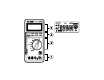
Operation Terminals, Shutter, & Test Leads SAFETY SHUTTER Slide up to open shutters for current measurement inputs. Must have the function switch in one of the Current Measurement positions to open shutter. Close shutter to change function switch to any other measurement function.
Operation Function Switch Switch Position Display 10A DC Current (1 mA to 10 A) DC Current (10 µA to 0.5 A) DC Current (1 µA to 0.05 A) DC Current (0.01 µA to 0.5 mA) AC Current (1 mA to 10 A) AC Current (10 µA to 0.5 A) AC Current (1 µA to 0.05 A) AC Current (0.01 µA to 0.5 mA) Diode Test Auto Diode Test Resistance ( 0.
Operation Function Keys Power Automatic power off after 30 minutes. Alarm sounds 30 seconds before automatic power off. Press any key or change any function to cancel automatic power off. Defeat automatic power off by holding key for 2 seconds while applying power.
Operation Minimum/Maximum Press 1 Action Begin recording of min, max, and avg values Main Display 3 Secondary Display Each measured value Elapsed time Display recorded maximum Maximum measurement Time of Maximum Display recorded minimum Minimum measurement Time of Minimum Display recorded average Calculated average Elapsed time Display last recorded measurement Latest measurement Elapsed time Pause recording of minimum and maximum values Resume recording of minimum and maximum values Las
Operation Hold/Auto-Hold Press Action Holds the measurement value in the display Enters Auto-Hold function 1 Cancels Hold function 1 Main Display Measurement value when hold pressed Secondary Display Input value Range Measurement value Range Range Auto-Hold Operation. When measurement becomes stable, multimeter will beep and save the stable reading. Removing probe from measurement circuit will display and hold the last stable reading.
Operation Function Keys and Function Switch Matrix Function Min/Max 3 Average Data Hold Auto-Hold • • • • • • • • • • • • • • • • • • • • • • • • •1 • • • V • • • • • • • • • • V • • • • µA, mA, 10A Ω °F, °C mV Hz+V • dBm 1-12 % (Percent) • • • µA, mA, 10A Hz Relative 1 Invokes zero adjust when display is less than 99. 2 Changes input attenuator, frequency is always auto range. 3 Secondary display shows elapsed time (in seconds and minutes).
Operation Display Low Battery indicator Replace batteries when on. Main Display (Not all annunciators shown) Number of digits is set by range and function Displays O.L to indicate an overload condition Entire display flashes if input overvoltage Secondary Display Shows: Range (most functions) except for Elapsed time (Min/Max) Audio Power on First beep at power on. Second beep when beginning to make measurements. Single beep Indicates any valid function key press.
Calibration and Adjustment Required Test Equipment The source used for the calibration should have an output accuracy as good or better than that listed in the specifications. Calibration Procedure Environmental range for calibration: 23° C ± 5° C, < 80% RH Calibration interval: 6 Months 1 Disconnect all inputs from the multimeter and open the case as described on page 6-5. 2 Install new batteries (described below) and close the cover. Turn the multimeter on and allow a 30 minute warm-up. Open the case.
Maintenance Operator protection from electric shock hazard is provided by a double insulated enclosure. Refer to pages 1-4 and 1-5 for maximum voltage specifications. When servicing, use only specified replacement parts. Battery Replacement Replace the battery when the symbol appears in the display or before calibration. Replace both batteries at the same time. Use high-quality type AA alkaline (IEC LR6) batteries. Remove the batteries if the multimeter is to be stored for extended periods of time.
Maintenance Troubleshooting Problem Possible Cause Suggested Action Unit won’t turn on Dead Batteries Unit won’t turn off Input limit exceeded Remove test leads and press any key to reset. Display flashes and Rapid beeps Input limit exceeded Remove test leads and press any key to reset.
Specifications Calibration period: six months minimum. Specifications apply at 23°C ± 5°C, < 80% RH Accuracy = ± (% of reading + number of digits) Temperature Coefficient = Accuracy 0.1/° C (0° C to 18° C; 28° C to 55° C) General Do not expose product to moisture or rain. Do not use product in flammable atmosphere. Operating Temperature: 0° to 40°C / 80% RH max (no condensation). Storage Temperature: -25°C to 60°C / 20% to 70°C RH (no condensation).
Specifications AC + DC Voltage (rms responding, computed from acV, dcV) Range Resolution 5V 50 V 500 V 1 mV 10 mV 100 mV ± (1% + 30) 750 V 1V ± (1% + 30) DC, 20 Hz to 1 kHz DC, 20 Hz to 10 kHz Measurement range: 500 mV to 500 V ranges 20 Hz to 30 kHz 30 kHz to 100 kHz 750 V range Accuracy DC, 10 kHz to DC, 30 kHz to 30 kHz 50 kHZ DC, 50 kHz to 100 kHz ± (1.2% + 40) ± (3.5% + 300) ± (2.
Specifications Resistance 1 Range Resolution 500 Ω 5.0 kΩ 50 kΩ 500 kΩ 5.0 MΩ 50 MΩ 10 mΩ 100 mΩ 1Ω 10 Ω 100 Ω 1 kΩ Accuracy ± (0.06% + 2) 1 ± (0.06% + 2) ± (0.5% + 1) ± (1.0% + 2) Test Current Max Open Circuit Voltage < 800 µA < 5.5 V < 80 µA < 15 µA < 1.5 µA < 150 nA < 2.2 V After zero adjust of input leads. Zero adjust range up to 0.99 Ω. Response time: 500 Ω to 500 kΩ — < 2 seconds, 5 MΩ to 50 MΩ — < 10 seconds. Continuity Measurement Current: 0.
Specifications Temperature (5 kΩ @ 25°C Thermistor probe) Measurement Range Resolution Accuracy 1 1 °C -80° to 150° 0.1° ± 0.2° °F -112° to 302° 0.1° ± 0.4° Accuracy does not include 5 k Ω Thermistor error dBm 600 Ω 1 mW reference (rms responding, computed from AC Voltage) Accuracy 10 kHz to 30 kHz to 30 kHz 50 kHz Input dBm Input Voltage 20 Hz to 10 kHz -29.82 dBm to -23.80 dBm -23.80 dBm to -3.80 dBm -3.80 dBm to 55.28 dBm 55.28 dBm to 59.72 dBm 25 mV to 50 mV ± 0.2 dBm ± 0.
Adjustments 6-1
Calibration Table CAUTION Dangerous voltages are present during the calibration procedure. Calibration should only be performed by qualified service technicians using a non-conductive tool. Step 1 2 3 4 5 6 7 8 9* 10 * 11 12 13 14 15 16 Function 500 mV 500 mV 50 V V 5V 500 V 1000 V V 5V * Repeat steps 9 and 10. 6-2 Range 500 mV 500 V 5V Short 480.0 mV -480.0 mV 48.000 V -48.000 V 4.800 V 480.
Calibration Table Step Function Range Input Signal Adjustment (limit) C3 (±20) — — — — zero adjust 1 9 (±5) — — — — — — — — Tolerance (counts) ±270 ±1740 ±270 ±366 ±105 ±1 ±30 ±30 ±30 ±30 ±242 ±482 ±2 ±146 ±146 ±146 50 mA 50 mA 48.000 V @ 10 kHz 48.000 V @ 100 kHz 48.000 V @ 200 Hz 480.00 mV @ 10 kHz 750.0 V @ 200 Hz Short 480.00 Ω 4.8000 kΩ 48.000 kΩ 480.00 kΩ 4.8000 MΩ 48.000 MΩ Short 480.00 µA 48.000 mA 32 500 mA 40 mA 480.00 mA — 33 10 A 10 A 10.
Replaceable Parts/Accessories Refer to the disassembly diagram on page 6-5.
Replaceable Parts/Accessories Disassembly WARNING Always disconnect the test leads before opening the case.
DECLARATION OF CONFORMITY according to ISO / IEC Guide 22 and EN 45014 Manufacturer’s Name: Manufacturer’s Address: Hewlett-Packard Company, Personal Measurements Operation 815 14th Street S.W., Loveland, Colorado 80537 U.S.A. declares, that the products Product Name: Model Number: Product Options: Handheld Multimeter HP 971A, HP 972A, HP 973A, HP 974A None conforms to the following Product Specifications: Safety: IEC 1010-01 (1990) Incl. Amend 1 (1992) / EN61010 (1993) CSA C22.2 #1010.
Warranty/Service Limited 3 Year Warranty What is Covered The HP 974A Multimeter is warranted by Hewlett-Packard against defects in materials and workmanship for three years from the date of original purchase. If you sell your unit or give it as a gift, the warranty is automatically transferred to the new owner and remains in effect for the original three year period.