HP FlexFabric Virtual Switch 5900v Configuration Examples Part number: 5998-4545 Document version: 6W101-20140320 © Copyright 2014 Hewlett-Packard Development Company, L.P. The information contained herein is subject to change without notice. The only warranties for HP products and services are set forth in the express warranty statements accompanying such products and services. Nothing herein should be construed as constituting an additional warranty.
Contents Introduction ··································································································································································· 1 Prerequisites ·································································································································································· 1 Configuration restrictions and guidelines ·······································································································
Introduction This document provides HP FlexFabric Virtual Switch 5900v configuration examples. The HP 5900v is a virtual switch designed for data center virtualization. It runs on top of the VMware vSphere Enterprise Plus Edition, and works seamlessly with the vCenter Server and VMware ESXi hosts (physical servers that run ESXi). You can use the 5900v virtual switch in place of the VMware virtual switch to provide enhanced distributed virtual switching capabilities.
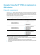
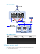
Example: Using the HP 5900v to implement an EVB solution Network requirements As shown in Figure 1, VMware, HP IMC, and HP 5900v virtual switch have been deployed. The HP 5900 switch provides network access for ESXi host 1 and ESXi host 2, and it is uplinked to an HP 10500 switch. Each host has four NICs. One NIC connects to the management network, one NIC connects to the iSCSI storage, and the other two connect to the service network.
Figure 1 Network diagram Table 1 IP address assignment Device IP address VM IP address VMware vCenter Server 192.168.20.65 Win-001 192.168.10.168 VCE 192.168.20.21 Win-002 192.168.30.165 HP IMC 192.168.20.35 Win-003 192.168.10.163 HP 5900 192.168.20.58 Win-005 192.168.30.169 Host 1 192.168.20.31 Host 2 192.168.20.
• HP 5900 E2305 (physical access switch) • HP IMC E0102L01 (IMC) Configuration procedures This example assumes that the devices on the management network (192.168.20.0/24) can ping each other. For information about HP IMC configurations, see HP IMC online help. For information about HP 5900 switch and HP 10500 switch configurations, see HP 5920&5900 Switch Series Configuration Guides and HP 10500 Switch Series Configuration Guides.
[Sysname-vlan100] quit [Sysname] vlan 200 [Sysname-vlan200] quit [Sysname] vlan 300 [Sysname-vlan300] quit # Create aggregate interface Bridge-Aggregation 1. Assign the ports connected to ESXi host 1 (Ten-GigabitEthernet 1/0/1 and Ten-GigabitEthernet 1/0/2) to aggregation group 1.
Configuring Ten-GigabitEthernet1/0/4 done. # Enable EVB on Bridge-Aggregation 2. [Sysname-Bridge-Aggregation2] evb enable [Sysname-Bridge-Aggregation2] quit # To enable Bridge-Aggregation 2 to quickly connect to the server, configure it as an STP edge port. [Sysname-Bridge-Aggregation2] stp edged-port # Assign FortyGigE 1/0/5 to VLAN 300.
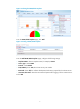
Figure 2 Selecting the SOAP/HTTP template # On the SOAP/HTTP Template page, click Add. Figure 3 Creating a SOAP/HTTP template # On the Add SOAP/HTTP Template page, configure the following settings: { Template Name—Enter a template name, for example, vCenter. { Access Type—Select SOAP. { Protocol—Select HTTPS. { Port(1-65535)—Enter 443, the vCenter server port number. { Root Path—Enter sdk, the software development kit directory required by the vCenter Server.
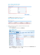
Figure 4 Adding a SOAP/HTTP template The vCenter template is displayed, as shown in Figure 5. Figure 5 SOAP/HTTP template creation completed 3. Add the vCenter Server, ESXi hosts, and the HP 5900 switch to HP IMC: a. Add the vCenter Server: # Click the Resource tab, and then select Add Device. Figure 6 Adding a device # On the Add Device page, enter the IP address of vCenter Server for Host Name/IP, select SSH from the Login Type list, and then click OK.
Figure 7 Adding the vCenter Server After the vCenter Server is added, HP IMC uses the vCenter template to create a connection to the vCenter Server automatically. b. Configure ESXi Host 1: # Click the Resource tab on the top navigation bar, and then select Add Device. # On the Add Device page, enter the IP address of ESXi Host 1 for Host Name/IP, and select SSH from the Login Type list. # Click Configure in the SSH Settings area to configure login authentication for ESXi Host 1.
Figure 8 Adding an ESXi host # On the page that appears, enter the username and password for logging in to ESXi Host 1, and then click OK. Figure 9 Configuring the login authentication c. Configure ESXi Host 2: # Click the Resource tab on the top navigation bar, and then select Add Device. # On the Add Device page, enter the IP address of ESXi Host 2 for Host Name/IP, and select SSH from the Login Type list. # Click Configure in the SSH Settings area to configure login authentication for ESXi Host 2.
Figure 10 Adding an ESXi host # On the page that appears, enter the username and password for logging in to ESXi Host 2, and then click OK. Figure 11 Configuring login authentication d. Configure the HP 5900 switch: # On the Add Device page, enter the IP address of HP 5900 switch for Host Name/IP, and select Telnet from the Login Type list. # Click SNMP Settings to configure SNMP settings for accessing the HP 5900 switch.
Figure 12 Adding the HP 5900 switch # On the page that appears, configure the same SNMP settings as you configured on the HP 5900 switch, and then click OK. Figure 13 Configuring SNMP information # Click Configure in the Telnet Settings area to configure Telnet for accessing the HP 5900 switch.
Figure 14 Expanding the Telnet Settings area # Configure the same login authentication as you configured on the HP 5900 switch: − To disable login authentication, select No Username + No Password from the Authentication Mode list, enter a timeout interval for Timeout (1-60 seconds), and then click OK.
4. Configure the HP 5900 switch as the Edge Switch on VCM. # Click the Resource tab on the top navigation bar, and then select VAN Connection Manager > Edge Switch from the left navigation tree. # Click Add. Figure 17 Adding an Edge Switch # On the page that appears, select Device View > Switches in the left navigation tree, select the 5900 switch (5900-2 in this example) in the Devices Found pane, and then click the Add icon The device label is user configurable on HP IMC.
Figure 19 Edge Switch adding completed Configuring services and features In the HP EVB solution, network policies are configured on the IMC. The VCE obtains the network policies for VM traffic from IMC and notifies IMC to issue the network policies to the VSIs on the access switch. On IMC, you must create a network (VLAN) for each service, associate the VLAN with a VSI type, and then configure the network policy for each VSI type. 1. Create networks (VLANs) for different services: a.
# On the Add Network page, specify the network name, VLAN ID, and maximum connections for the mail service, as shown in Figure 21. NOTE: The maximum connections setting limits the number of concurrent accesses to the ESXi host in the VLAN. Figure 21 Configuring network attributes # Click OK. b. Create a network for file service: # Click the Add tab on the Network page, as shown in Figure 20.
Figure 23 Configuring network attributes # Click OK. The three VLAN networks are displayed on the Network page. Figure 24 Network creation completed 2. Create VSI types and associate the networks with their respective VSI types: a. Create a VSI type for mail service: # Select VAN Connection Manager > VSI Type from the navigation tree. # Click the Add tab on the VSI Type page.
Figure 25 Adding a VSI type # On the page that appears, configure the VSI type and network policy, as shown in Figure 26: Area Items • Name—Enter the VSI type name. For easy management, you can set the VSI type name to be the same as the network name. Basic Information • Network—Select the network to be associated with the VSI type. In this example, select the network (VLAN100) created for mail service. • Description—Enter a VSI description for management purposes.
Figure 26 Configuring network policies # Click Save and Release. b. Create a VSI type for file service and associate the VSI type with the file service network (VLAN 200). # Click the Add tab on the VSI Type page, as shown in Figure 25. # On the page that appears, configure the VSI type and network policy, as shown in Figure 27: Area Items • Name—Enter the VSI type name. For easy management, you can set the VSI name to be the same as the network name.
Area Items the client. Select OUTBOUND to apply the QoS settings to traffic from the client to the VM server. Figure 27 Configuring network policies # Click Save and Release. c. Create a VSI type for other services and associate the VSI type with the other service network (VLAN 300). # Click the Add tab on the VSI Type page, as shown in Figure 25. # On the page that appears, configure the VSI type and network policy, as shown in Figure 28: Area Items • Name—Enter the VSI type name.
Area Items green check sign (9) transiently in front of each parameter required for the action type. IMPORTANT: These QoS settings will be applied to the VSIs created on the physical access switch for VMs. When you set the filtering direction, select INBOUND to apply the QoS settings to the traffic from the VM server to the client. Select OUTBOUND to apply the QoS settings to traffic from the client to the VM server. Figure 28 Configuring network policies # Click Save and Release.
Figure 29 Configuring network policies Configuring the HP 5900v virtual switch HP 5900v configuration includes the following tasks: • Install a VFE on each ESXi host to forward VM traffic. • Access the vCenter from the vSphere Client to perform the following tasks: Task Description Create a VDS and assign all ESXi hosts to the VDS. This VDS is a switching domain.
NOTE: The HP 5900v configuration tab appears immediately after you complete installing the VMware plug-in. The tab name is user configurable. This example uses HP VDS 5900v. Figure 30 Configuring the HP 5900v # Select the ESXi hosts, and then click Install. Figure 31 Installing the VFE The Licensing Status for the hosts will change to Licensed after the installation is completed. 3.
Figure 33 Creating a VDS # Right-click the VDS name (HP-VDS) in the navigation tree, and then select Add Host from the shortcut menu. Figure 34 Adding hosts # Select the IP addresses (192.168.20.31 and 192.168.20.33) of the ESXi hosts, and then select their physical NICs for uplink connections, as shown in Figure 35. In this example, select vmnic1 and vmnic2 for both hosts. # Click Next.
Figure 35 Selecting ESXi hosts and physical NICs # On the Network Connectivity page, click Next without selecting any VMkernel adapters. NOTE: The tasks on this page are for VMkernel to provide vMotion and iSCSI management. You do not need to perform these tasks, because they are irrelevant to the network services that the VDS is intended to provide.
Figure 36 Network Connectivity page # On the Virtual Machine Networking page, click Next. NOTE: The tasks on this page are not available because you have not created any port groups for VMs yet.
Figure 37 Virtual Machine Networking page # On the Ready to Complete page, verify the uplink group and VM port group settings for the VDS, and then click Finish. NOTE: Because you have not created any port groups for VMs, the page displays only the default port group, and this group does not contain any VMs.
Figure 38 Ready to Complete page 4. Configure the uplink group: # Click the VDS name (HP-VDS) in the navigation tree. # On the HP Port Group 5900v tab, click the Configuration link for the uplink group (HP-VDSdefaultUplinkGroup). NOTE: • The port group tab for 5900v is named in the HP Port Group plug-in-name format. The plug-in name is user configurable during VCE installation. • The uplink group name for a VDS uses the vdsdefaultUplinkGroup format, where vds represents the VDS name.
NOTE: An aggregation group takes effect only when the member ports have the same following configurations: • Port rate. • Duplex mode. • Link type. • VLAN ID Figure 40 Displaying link aggregation mode and configuring load sharing criteria for the physical NICs 5. Create a downlink port group for mail service: # On the HP Port Group 5900v tab, click Create at the top left of the configuration pane.
# On the HP Port Group 5900v tab, click the link in the VLAN column to configure VLAN settings for the port group. Figure 43 Clicking the VLAN link for the port group # Select VLAN Access, enter the VLAN ID for mail service, and then click OK. NOTE: For downlink ports (virtual NICs), you must set the link type to Access. Figure 44 Configuring VLAN settings # On the HP Port Group 5900v tab, click the link in the VDP column to associate the downlink port group with the network and VSI type settings.
Figure 46 Configuring VDP settings for the port group 6. Create a downlink port group for file service: # On the HP Port Group 5900v tab, click Create at the top left of the configuration pane. Figure 47 HP Port Group 5900v tab # Enter a port group name (for example, VLAN 200), set the maximum number of downlink virtual NICs allowed in the group, and then click OK.
Figure 50 Configuring VLAN settings # On the HP Port Group 5900v tab, click the link in the VDP column to associate the downlink port group with the network and VSI type settings. Figure 51 Clicking the VDP link for the port group # Select the network, VSI type, and VSI type version configured on HP IMC for file service, and then click OK. Figure 52 Configuring VDP settings for the port group Figure 53 shows the two downlink port groups you configured for mail and file services.
Figure 54 VM configuration page # On the VM properties page, select a virtual NIC from the Hardware list, select the mail service downlink port group from the Network label list, and then click OK. NOTE: • To assign multiple virtual NICs to a port group, repeat the operations of virtual NIC and port group selection before you click OK. • In the Network label list, the VDS name is appended automatically to the port group name. For example, VLAN100 (HP-VDS) represents the VLAN100 port group in HP-VDS.
Figure 55 Assigning virtual NICs of a VM to a port group # Repeat the previous steps to assign Win-003 to the VLAN100 port group, and assign Win-003, and Win-005 to the VLAN200 port group. 8. Create a PVLAN for other service: # On the Virtual Distributed Switch page, click the VDS2 link. Figure 56 Entering the VDS Information page # Click Add in the Private VLAN area. Figure 57 Adding a private VLAN # Enter the primary VLAN and secondary VLAN (community), and click OK.
Figure 58 Configuring the primary VLAN and the secondary VLAN # On the HP Port Group F0203 tab, click the link in the VLAN column to configure VLAN settings for the port group. Figure 59 Clicking the VLAN link for the port group # Select PVLAN, and select Community VLAN (300,321) from the list, and click OK.
Figure 61 Clicking the VDP link for the port group # Select the network, VSI type, and VSI type version configured on HP IMC for other services, and then click OK. Figure 62 Configuring VDP settings for the port group NOTE: With HP IMC, you can revise the settings of a VSI type. Each time a revised VSI type is released, HP IMC creates a new version of the VSI type. If a VSI type has been revised multiple times, The VSI Type Version list will contain multiple versions.
After the port group configurations for the VMs are completed, the HP 5900v obtains network policies for the VMs after the VMs are powered on. IMC then issues the policies to the HP 5900 switch. 2. Verify that IMC has issued the network policies to the HP 5900 switch. # Display brief VSI information for Bridge-Aggregation 1. display evb vsi interface Bridge-Aggregation 1 Status: A -- Association, P -- Pre-association VSI VTID interface Type Instance version ID Status SCH-AGG1:1.
Yellow action : pass Red action : discard Classifier: deny-0050-568d-7f98 Operator: AND Rule(s) : If-match protocol ip Behavior: denyBehav-0050-568d-7f98 Filter enable: Deny Interface: Schannel-Aggregation1:1.1 Direction: Inbound Policy: Schannel-Aggregation1:1.
Figure 64 Selecting Win-005 for VM migration # On the Migrate Virtual Machine page, select Change host, and click Next.
# Select 192.168.20.31 as the destination host, and click Next. Figure 66 Selecting the destination host for VM migration # Select High priority (Recommended) for vMotion Priority, and click Next.
Figure 67 Setting the priority of the vMotion migrations # Click Finish to start migration.
Figure 68 Ready to Complete page Figure 69 shows that the VM Win-005 has been migrated to Host 1 at 192.168.20.31.
Figure 69 Migration completed # Log in to the HP 5900v switch, and display the running configuration on Bridge-Aggregation 2. system-view [Sysname] interface Bridge-Aggregation 2 [Sysname-Bridge-Aggregation2] display this # interface Bridge-Aggregation2 evb enable port link-type trunk undo port trunk permit vlan 1 port trunk permit vlan 100 # The output shows that Bridge-Aggregation 2 has not been assigned to VLAN 200. # Display brief VSI information for Bridge-Aggregation 2.
# Display information about the QoS policy applied to the incoming traffic of Schannel-Aggregation 2:1. display qos policy interface Schannel-Aggregation 2:1 Interface: Schannel-Aggregation2:1.0 Direction: Inbound Policy: Schannel-Aggregation2:1.