Maintenance and Service Guide HP EliteDesk 800 G2 Desktop Mini HP EliteDesk 705 G2 Desktop Mini HP ProDesk 600 G2 Desktop Mini HP ProDesk 400 G2 Desktop Mini HP MP9 G2 Retail System
© Copyright 2015, 2016 HP Development Company, L.P. AMD is a trademark of Advanced Micro Devices, Inc. Bluetooth is a trademark owned by its proprietor and used by HP Inc. under license. Intel, Celeron, and Pentium are trademarks of Intel Corporation in the U.S. and other countries. Microsoft and Windows are trademarks of the Microsoft group of companies. The information contained herein is subject to change without notice.
Safety warning notice WARNING! To reduce the possibility of heat-related injuries or of overheating the device, do not place the device directly on your lap or obstruct the device air vents. Use the device only on a hard, flat surface. Do not allow another hard surface, such as an adjoining optional printer, or a soft surface, such as pillows or rugs or clothing, to block airflow. Also, do not allow the AC adapter to contact the skin or a soft surface, such as pillows or rugs or clothing, during operation.
iv Safety warning notice
Table of contents 1 Product features ....................................................................................................................................................................................... 1 Standard configuration features ............................................................................................................................................ 1 Front panel components (EliteDesk 800, ProDesk 600, and HP MP9) ..................................................
SATA hard drive cables .......................................................................................................................................................... 18 SATA data cable .................................................................................................................................................. 18 SMART ATA drives ....................................................................................................................................................
Recovering the Configuration Settings ............................................................................................................................... 70 6 Troubleshooting without diagnostics ................................................................................................................................................. 71 Safety and comfort .........................................................................................................................................
Recovering using HP Recovery Manager ................................................................................ 118 What you need to know before you get started ............................................... 118 Using the HP Recovery partition (select products only) .................................. 119 Using HP Recovery media to recover .................................................................. 119 Changing the computer boot order ............................................................
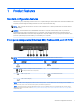
1 Product features Standard configuration features Features may vary depending on the model. For a complete listing of the hardware and software installed in the computer, run the diagnostic utility (included on some computer models only). NOTE: This computer model can be used in a tower orientation or a desktop orientation. The tower stand is sold separately. CAUTION: Several well-known vulnerabilities exist when a computer is in the Sleep state.
Front panel components (EliteDesk 705 and ProDesk 400) NOTE: Your computer model may look slightly different from the illustration in this section. Item Component Item Component 1 Headphone Connector 4 USB 3.0 Port 2 Microphone Connector 5 HDD Activity LED 3 USB 3.0 Port-Charging 6 Dual-State Power Button NOTE: This USB 3.0 connector does not offer port charging on 400 models. NOTE: The USB 3.0 Port–Charging also provides current to charge a device such as a Smart Phone.
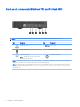
Rear panel components (EliteDesk 800, EliteDesk 705, ProDesk 600, and HP MP9) NOTE: Your computer model may look slightly different from the illustration in this section. Item Component Item Component 1 External Antenna Connector (optional) 8 VGA Monitor Connector 2 Thumbscrew 9 DisplayPort (default, shown), HDMI, or Serial Connector 3 Padlock Loop 10 USB 3.0 Ports (2) (blue) 4 Cable Lock Slot 11 USB 3.
Rear panel components (ProDesk 400) NOTE: Your computer model may look slightly different from the illustration in this section. 4 Item Component Item Component 1 External Antenna Connector (optional) 8 VGA Monitor Connector 2 Thumbscrew 9 Serial Port 3 Padlock Loop 10 USB 3.0 Ports (2) (blue) with support for wake from S4/S5 power states 4 Cable Lock Slot 11 USB 2.
Serial number location Each computer has a unique serial number and a product ID number that are located on the exterior of the computer. Keep these numbers available for use when contacting customer service for assistance.
2 Illustrated parts catalog Desktop Mini (DM) chassis spare parts NOTE: HP continually improves and changes product parts. For complete and current information on supported parts for your computer, go to http://partsurfer.hp.com, select your country or region, and then follow the on-screen instructions.
Item Description (5) Memory modules (DDR3, PC3-12800, 1600-MHz)(for use in EliteDesk 705 models) 8-GB 4-GB * Memory modules (DDR4, PC4-17000, 2133-MHz)(for use in EliteDesk 800, ProDesk 600, ProDesk 400, and MP9 models) 16-GB 8-GB 4-GB * Intel Processors (800, 600, 400, MP9 models; include replacement thermal material) Intel Core i7-6700 Intel Core i7-6700T Intel Core i5-6600 Intel Core i5-6600T Intel Core i5-6500 Intel Core i7-6500T Intel Core i3-6320 Intel Core i3-6300T Intel Core i3-6100T Intel Pe
Cables 8 Item Description (1) SATA cable/connector * Adapter, DisplayPort to HDMI 1.4 * Adapter, DisplayPort to VGA * Adapter, DisplayPort to DVI * Adapter, USB-C to USB 3.
Misc parts Item Description (1) Heat sink (2) Fan (3) Secondary hard drive fan (for use in EliteDesk 800 and MP9, 65W models) (4) Speaker (5) Power switch/light cover (6) Option board, HDMI (7) Option board, serial port * Option board, DisplayPort (not illstrated) (8) Thermal sensor (9) Hood sensor assembly * Stand * Port cover * HP Ultraslim Keyed Cable Lock Desktop Mini (DM) chassis spare parts 9
Item Description * WLAN modules: Intel Dual Band Wireless-AC 7265 NV Intel Dual Band Wireless-AC 8260 + Bluetooth 4.0 Intel Dual Band Wireless-AC 3165 + Bluetooth 4.0 HP WLAN 802.11 a/b/g/n + Bluetooth 4.0 * Antenna, dual band dipole, 802.11a/b/g/n + Velcro * External antenna kit * Expansion Module Kit Hard drive – I/O (includes screws) I/O Optical drive USB 3.0 Type A-B USB 3.
Drives Description Hard drives 2 TB, 5400 rpm, hard drive, 2.5-inch 1 TB, 7200 rpm, hard drive, 2.5-inch 1 TB, 7200 rpm, hard drive, 2.5-inch, SSHD (hybrid SSD) 500 GB, 7200 rpm hard drive, 2.5-inch 500 GB, 2.5-inch, SSHD (hybrid SSD) 500 GB, 7200 rpm hard drive, 2.5-inch, OPAL 2, SED 500 GB, 5400 rpm hard drive, 2.
3 Routine care, SATA drive guidelines, and disassembly preparation This chapter provides general service information for the computer. Adherence to the procedures and precautions described in this chapter is essential for proper service. CAUTION: When the computer is plugged into an AC power source, voltage is always applied to the system board. You must disconnect the power cord from the power source before opening the computer to prevent system board or component damage.
Preventing electrostatic damage to equipment Many electronic components are sensitive to ESD. Circuitry design and structure determine the degree of sensitivity. The following packaging and grounding precautions are necessary to prevent damage to electric components and accessories. ● To avoid hand contact, transport products in static-safe containers such as tubes, bags, or boxes. ● Protect all electrostatic parts and assemblies with conductive or approved containers or packaging.
Recommended materials and equipment Materials and equipment that are recommended for use in preventing static electricity include: ● Antistatic tape ● Antistatic smocks, aprons, or sleeve protectors ● Conductive bins and other assembly or soldering aids ● Conductive foam ● Conductive tabletop workstations with ground cord of one-megohm +/- 10% resistance ● Static-dissipative table or floor mats with hard tie to ground ● Field service kits ● Static awareness labels ● Wrist straps and footwea
Routine care General cleaning safety precautions 1. Never use solvents or flammable solutions to clean the computer. 2. Never immerse any parts in water or cleaning solutions; apply any liquids to a clean cloth and then use the cloth on the component. 3. Always unplug the computer when cleaning with liquids or damp cloths. 4. Always unplug the computer before cleaning the keyboard, mouse, or air vents. 5. Disconnect the keyboard before cleaning it. 6.
CAUTION: Never remove a wide leveled key (like the space bar) from the keyboard. If these keys are improperly removed or installed, the keyboard may not function properly. ● Cleaning under a key may be done with a swab moistened with isopropyl alcohol and squeezed out. Be careful not to wipe away lubricants necessary for proper key functions. Use tweezers to remove any fibers or dirt in confined areas. Allow the parts to air dry before reassembly.
Cables and connectors Most cables used throughout the unit are flat, flexible cables. These cables must be handled with care to avoid damage. Apply only the tension required to seat or unseat the cables during insertion or removal from the connector. Handle cables by the connector whenever possible. In all cases, avoid bending or twisting the cables, and ensure that the cables are routed in such a way that they cannot be caught or snagged by parts being removed or replaced.
Serial ATA Hard Drive Characteristics Maximum data cable length 39.37 in (100 cm) Data interface voltage differential 400-700 mV Drive voltages 3.3 V, 5 V, 12 V Jumpers for configuring drive N/A Data transfer rate 6.0 Gb/s SATA hard drive cables SATA data cable Always use an HP approved SATA 6.0 Gb/s cable as it is fully backwards compatible with the SATA 1.5 Gb/s drives. Current HP desktop products ship with SATA 6.0 Gb/s hard drives. SATA data cables are susceptible to damage if overflexed.
Cable management Always follow good cable management practices when working inside the computer. ● Keep cables away from major heat sources like the heat sink. ● Do not jam cables on top of expansion cards or memory modules. Printed circuit cards like these are not designed to take excessive pressure on them. ● Keep cables clear of sliding or moveable parts to prevent them from being cut or crimped when the parts are moved. ● When folding a flat ribbon cable, never fold to a sharp crease.
4 Removal and replacement procedures – desktop mini (DM) chassis Adherence to the procedures and precautions described in this chapter is essential for proper service. After completing all necessary removal and replacement procedures, run the Diagnostics utility to verify that all components operate properly. NOTE: Not all features listed in this guide are available on all computers. NOTE: HP continually improves and changes product parts.
Top cover 1. Prepare the computer for disassembly (Preparation for disassembly on page 20). 2. Loosen the thumbscrew on the rear of the computer (1). 3. Slide the panel forward and lift if off the computer (2). NOTE: Your computer model may look slightly different from the illustration in this section. To install the top cover, reverse the removal procedure.
Front bezel The front bezel is secured to the top cover by tabs. 1. Prepare the computer for disassembly (Preparation for disassembly on page 20). 2. Remove the top cover (Top cover on page 21). 3. Position the top cover upside-down so you can access the inside of the bezel. 4. Pull down to loose the bottom, interior on the bezel (1). 5. Disengage the tabs on the top, interior of the bezel (2). 6. Remove the bezel from the top cover. To install the front bezel, reverse the removal procedure.
Hard drive Description Hard drives 2 TB, 5400 rpm, hard drive, 2.5-inch 1 TB, 7200 rpm, hard drive, 2.5-inch 1 TB, 7200 rpm, hard drive, 2.5-inch, SSHD (hybrid SSD) 500 GB, 7200 rpm hard drive, 2.5-inch 500 GB, 2.5-inch, SSHD (hybrid SSD) 500 GB, 7200 rpm hard drive, 2.5-inch, OPAL 2, SED 500 GB, 5400 rpm hard drive, 2.
24 4. Pull the release lever next to the rear of the HDD away from the HDD (2). While pulling the release lever out, slide the drive back until it stops, then lift the HDD up and out of the cage (3). 5. To install a HDD, you must transfer the silver and blue isolation mounting guide screws from the old HDD to the new HDD. 6. Align the guide screws with the slots on the chassis drive cage, press the HDD down into the cage, then slide it forward until it stops and locks in place (1).
7. Connect the HDD power and data cable (2) to the HDD. Reverse this procedure to replace the hard drive.
Secondary fan (EliteDesk 800 and MP9 models only) HP EliteDesk 800 G2 and HP MP9 G2 Retail System models include a secondary fan installed under the hard drive. 1. Prepare the computer for disassembly (Preparation for disassembly on page 20). 2. Remove the top cover (Top cover on page 21). 3. Remove the hard drive (Hard drive on page 23). 4. Disconnect the fan plug from the system board (1). 5. Remove the two screws securing the secondary fan (2). 6. Lift the fan out of the chassis (3).
Drive cage The drive cage is located next to the heat sink. The drive cage is secured with three Phillips screws. 1. Prepare the computer for disassembly (Preparation for disassembly on page 20). 2. Remove the top cover (Top cover on page 21). 3. Remove the hard drive (Hard drive on page 23). 4. Remove the three screws securing the HDD cage to the chassis (1). 5. Pull the hood sensor up and off the HDD cage (2). 6. Lift the HDD cage out of the chassis (3).
M.2 PCIe solid state drive (SSD) Description 256 GB solid-state drive (SSD), PCIe, 2280, NVMe 256 GB solid-state drive (SSD), PCIe, 2280SS 128 GB solid-state drive (SSD), PCIe, 2280, NVMe 128 GB solid-state drive (SSD), PCIe, 2280SS 1. Prepare the computer for disassembly (Preparation for disassembly on page 20). 2. Remove the top cover Top cover on page 21. 3. Remove the hard drive (Hard drive on page 23). 4.
11. Press the SSD down to the system board and use the included screw to secure the SSD. M.
WLAN module Description Intel Dual Band Wireless-AC 7265 NV Intel Dual Band Wireless-AC 8260 + Bluetooth 4.0 Intel Dual Band Wireless-AC 3165 + Bluetooth 4.0 HP WLAN 802.11 a/b/g/n + Bluetooth 4.0 The WLAN module is secured with one Phillips screw and has two connected antennas. It is located under the hard drive. 1. Prepare the computer for disassembly (Preparation for disassembly on page 20). 2. Remove the top cover (Top cover on page 21). 3. Remove the hard drive (Hard drive on page 23). 4.
12. Attach the internal antenna to the antenna connectors (3) on the WLAN module. To install the WLAN module, reverse the removal procedure. NOTE: WLAN modules are designed with a notch to prevent incorrect insertion.
External antenna The antennas route from the WLAN module to the cable connectors on the rear of the computer. To install the antennas: 1. Prepare the computer for disassembly (Preparation for disassembly on page 20). 2. Remove the top cover (Top cover on page 21). 3. Remove the hard drive (Hard drive on page 23). 4. If your model is an EliteDesk 800 or MP9, remove the secondary fan (Secondary fan (EliteDesk 800 and MP9 models only) on page 26). 5. Remove the drive cage (Drive cage on page 27). 6.
9. Insert a Phillips screwdriver in each knock-out feature and rotate to remove the blank. 10. Feed the external antenna cable through each hole and screw the antenna into position. 11. Connect the external antenna cables to the WLAN module. Reverse the removal procedure to install the WLAN antennas and transceivers.
RTC battery The battery that comes with the computer provides power to the real-time clock. When replacing the battery, use a battery equivalent to the battery originally installed in the computer. The computer comes with a 3-volt lithium coin cell battery. WARNING! The computer contains an internal lithium manganese dioxide battery. There is a risk of fire and burns if the battery is not handled properly. To reduce the risk of personal injury: Do not attempt to recharge the battery.
6. Locate the battery and battery holder on the system board. NOTE: You may need to use a small tool, such as tweezers or needle-nose pliers, to remove and replace the battery. 7. Lift the battery out of the holder. 8. Slide the replacement battery into position, positive side up. The battery holder automatically secures the battery in the proper position.
Thermal sensor A thermal sensor installs at the front of the computer near the speaker. Adhesive secures the sensor to the chassis that houses the speaker. To remove the thermal sensor: 1. Prepare the computer for disassembly (Preparation for disassembly on page 20). 2. Remove the top cover (Top cover on page 21). 3. Remove the hard drive (Hard drive on page 23). 4. If your model is an EliteDesk 800 or MP9, remove the secondary fan (Secondary fan (EliteDesk 800 and MP9 models only) on page 26). 5.
Fan The fan sits between the fan sink and the front of the computer. 1. Prepare the computer for disassembly (Preparation for disassembly on page 20). 2. Remove the top cover (Top cover on page 21). 3. Lift the tab on the outer edge of the fan and rotate the fan upward. 4. Disconnect the fan plug from the system board, and then lift the fan out of the chassis. To install the fan, reverse the removal procedure.
Power switch/light cover The power switch/light cover is located at the front, right of the computer, under the top cover. 1. Prepare the computer for disassembly (Preparation for disassembly on page 20). 2. Remove the top cover (Top cover on page 21). 3. Remove the fan (Fan on page 37). 4. Rotate the top of the cover away from the computer and lift it off the system board. To install the power switch/light cover, reverse the removal procedure.
Memory Description Memory modules (PC3-12800, 1600-MHz)(for use in EliteDesk 705 models) 8-GB 4-GB Memory modules (PC4-17000, 2133-MHz)(for use in EliteDesk 800, ProDesk 600, ProDesk 400, and HP MP9 G2 Retail System models) 16-GB 8-GB 4-GB The computer comes with small outline, dual inline memory modules (SODIMMs). SODIMMs The memory sockets on the system board can be populated with up to two industry-standard SODIMMs. These memory sockets are populated with at least one preinstalled SODIMM.
HP offers upgrade memory for this computer and advises that the consumer purchase it to avoid compatibility issues with unsupported third-party memory. Populating SODIMM sockets There are two SODIMM sockets on the system board, with one socket per channel. The sockets are labeled DIMM1 and DIMM3. The DIMM1 socket operates in memory channel B. The DIMM3 socket operates in memory channel A.
Replacing SODIMMs CAUTION: You must disconnect the power cord and wait approximately 30 seconds for the power to drain before adding or removing memory modules. Regardless of the power-on state, voltage is always supplied to the memory modules as long as the computer is plugged into an active AC outlet. Adding or removing memory modules while voltage is present may cause irreparable damage to the memory modules or system board. The memory module sockets have gold-plated metal contacts.
5. To remove a SODIMM, press outward on the two latches on each side of the SODIMM (1) then pull the SODIMM out of the socket (2). 6. Slide the new SODIMM into the socket at approximately a 30° angle (1) then press the SODIMM down (2) so that the latches lock it in place. NOTE: A memory module can be installed in only one way. Match the notch on the module with the tab on the memory socket. The computer automatically recognizes the additional memory when you turn on the computer.
Heat sink The heat sink is secured with four captive Torx screws. order indicated on the heat sink. 1. Prepare the computer for disassembly (Preparation for disassembly on page 20). 2. Remove the top cover (Top cover on page 21). 3. Remove the fan (Fan on page 37). 4. In the order indicated on the heat sink, loosen the three captive Torx screws, and then lift the heat sink out of the computer. CAUTION: Be sure the loosen the screws in the order indicated by the numbers stamped on the heat sink.
44 Chapter 4 Removal and replacement procedures – desktop mini (DM) chassis
Processor – Intel models Description Intel Core i7-6700 Intel Core i7-6700T Intel Core i5-6600 Intel Core i5-6600T Intel Core i5-6500 Intel Core i7-6500T Intel Core i3-6320 Intel Core i3-6300T Intel Core i3-6100T Intel Pentium G4500T Intel Pentium G4400T Intel Pentium G4400TE (MP9 G2 models only) Intel Celeron G3900T Intel Pentium G3900TE (MP9 G2 models only) 1. Prepare the computer for disassembly (Preparation for disassembly on page 20). 2. Remove the top cover (Top cover on page 21). 3.
7. Lift the processor (3) straight up and remove it. CAUTION: Do NOT handle the pins in the processor socket. These pins are very fragile and handling them could cause irreparable damage. Once pins are damaged it may be necessary to replace the system board. The heat sink must be installed within 24 hours of installing the processor to prevent damage to the processor’s solder connections. Reverse the removal procedure to install a new processor.
Speaker A single speaker is located on the left side of the computer behind the front bezel, inside the chassis. It is secured by a white peg that you pull out to release. To remove the speaker: 1. Prepare the computer for disassembly (Preparation for disassembly on page 20). 2. Remove the top cover (Top cover on page 21). 3. Remove the hard drive (Hard drive on page 23). 4. Remove the hard drive cage (Drive cage on page 27). 5. Disconnect the speaker cable from the system board connector (1). 6.
Expansion connector board Description HDMI expansion connector board Serial port expansion connector board DisplayPort expansion connector board An expansion board can be installed near the back of the system board that provides an additional connector on the rear I/O panel. The board is secured with two screws and connects to the a connector on the system board. To remove the expansion connector board: 1. Prepare the computer for disassembly (Preparation for disassembly on page 20). 2.
System board NOTE: All system board spare part kits include replacement thermal material. NOTE: System board appearance may vary. 1. Prepare the computer for disassembly (Preparation for disassembly on page 20). 2. Remove the top cover (Top cover on page 21). 3. Remove the hard drive (Hard drive on page 23). 4. If your model is an EliteDesk 800 or MP9, remove the secondary fan (Secondary fan (EliteDesk 800 and MP9 models only) on page 26). 5. Remove the drive cage (Drive cage on page 27). 6.
To install the system board, reverse the removal procedures. NOTE: When replacing the system board, you must change the chassis serial number in the BIOS. Updating SMBIOS Information When replacing the system board, you must reprogram the SMBIOS information on the affected computer. Failure to reprogram the board will result in eventual failure, such as an activation failure (need to reactivate the system) or a system recovery failure. To update SMBIOS information in Computer Setup: 1.
System board callouts, EliteDesk 800, ProDesk 600, and HP MP9 Retail System Sys Bd Label Color Component Sys Bd Label Color Component SPKR White Speaker connector HDD_FAN White Secondary hard drive HSENSE White Hood sensor connector SATA Blue Hard drive data connector THERM White Thermal sensor COMM_DP White Expansion board connector SSD Black Solid-state module socket XU1 Black Processor socket WLAN Black WLAN module socket DIMM3 Black Secondary memory socket BAT Black
System board callouts, EliteDesk 705 52 Sys Bd Label Color Component Sys Bd Label Color Component SPKR White Speaker connector PSWD Black/blue Password header and jumper HSENSE White Hood sensor connector CMOS Yellow CMOS reset button THERM White Thermal sensor SATA Blue Hard drive data connector SSD Black Solid-state module socket DIMM3 Black Secondary memory socket WLAN Black WLAN module socket DIMM1 Black Primary memory socket BAT Black RTC battery CPU FAN White
System board callouts, ProDesk 400 Sys Bd Label Color Component Sys Bd Label Color Component DIMM3 Black Secondary memory socket WLAN Black WLAN module socket DIMM1 Black Primary memory socket BAT Black RTC battery CPUFAN White Fan connector PSWD Black/blue Password header and jumper SPKR White Speaker connector CMOS Yellow CMOS reset button HSENSE White Hood sensor connector SATA0 Blue Hard drive data connector THERM White Thermal sensor PROCESSOR Black Processor s
Internal WLAN antenna cable removal/installation The antennas route from the WLAN module to the cable connectors on the front and the rear of the computer. To install the antennas: 1. Prepare the computer for disassembly (Preparation for disassembly on page 20). 2. Remove the top cover (Top cover on page 21). 3. Remove the hard drive (Hard drive on page 23). 4. If your model is an EliteDesk 800 or MP9, remove the secondary fan (Secondary fan (EliteDesk 800 and MP9 models only) on page 26). 5.
14. On the rear of the computer, remove the antenna cover by pressing on the tab on the top of the cover (1), and then rotating the cover off the computer (2). 15. Antenna transceivers are connected to the front and back of the computer as shown in the following image. 16. Remove the front transceiver from the inside of the computer by pressing the tab to disengage the transceiver and removing the transceiver (arrow in following image points to the tabs on the inside of the computer).
17. Remove the rear transceiver from the inside of the computer by pressing the tab to disengage the transceiver and removing the transceiver (arrow in following image points to the tabs on the inside of the computer). Reverse the removal procedure to install the WLAN antennas and transceivers.
Changing from desktop to tower configuration The computer can be used in a tower orientation with an optional tower stand that can be purchased from HP. 1. Prepare the computer for disassembly (Preparation for disassembly on page 20). 2. Orient the computer so that its right side is facing up and place the computer in the optional stand. NOTE: To stabilize the computer in a tower orientation, HP recommends the use of the optional tower stand. 3.
5 Computer Setup (F10) Utility Computer Setup (F10) Utilities Use Computer Setup (F10) Utility to do the following: ● Change settings from the defaults or restore the settings to default values. ● View the system configuration, including settings for processor, graphics, memory, audio, storage, communications, and input devices. ● Modify the boot order of bootable devices such as hard drives, optical drives, or USB flash media devices.
4. Use the arrow (left and right) keys to select the appropriate heading. Use the arrow (up and down) keys to select the option you want, then press Enter. To return to the Computer Setup Utilities menu, press Esc. 5. To apply and save changes, select Main > Save Changes and Exit. ● If you have made changes that you do not want applied, select Ignore Changes and Exit. ● To restore settings from the Advanced and Main menus to original values, select Apply Factory Defaults and Exit.
Computer Setup–Main NOTE: Support for specific Computer Setup options may vary depending on the hardware configuration. Table 5-1 Computer Setup—Main Option Description System Information Lists all information in following list if Advanced System Information is selected. Lists smaller subset if Basic System Information is selected.
Table 5-1 Computer Setup—Main (continued) Option Description ● Lock BIOS Version If this option is checked, the system is locked to the current BIOS version and updates are not allowed. ● BIOS Update Preferences Allows the administrator to select the source of network updates (www.hp.
Computer Setup—Security NOTE: Support for specific Computer Setup options may vary depending on the hardware configuration. Table 5-2 Computer Setup—Security Option Description Set up BIOS Administrator Password Lets you set and enable a BIOS administrator password, which includes the following privileges: ● Manage other BIOS users ● Full access to BIOS policy and settings ● Unlock the computer when other BIOS users fail the preboot authentication.
Table 5-2 Computer Setup—Security (continued) Option Description ● Data Recovery Policy Select ‘Automatic’ or ‘Manual’ to set data recovery policy. ‘Manual’ lets you select whether or not to execute recovery of a corrupted region if it is detected. Set Up BIOS Power-On Password Lets you set and enable a BIOS power-on password. The power-on password prompt appears after a power cycle or reboot. If the user does not enter the correct power-on password, the unit will not boot.
Table 5-2 Computer Setup—Security (continued) Option Description Smart Cover Cover Lock (Lock/Unlock) Default is ‘Unlock’. Cover Removal Sensor (Disabled/Notify user/Administrator password) Lets you disable the cover sensor or configure what action is taken if the computer cover was removed. Default is ‘Disabled’. NOTE: Notify user alerts the user with a POST error on the first boot after the sensor detects removal of the cover.
Table 5-3 Computer Setup—Advanced (for advanced users) (continued) Option Heading Default is enabled. Specify the order in which UEFI boot sources (such as a internal hard drive, USB hard drive, USB optical drive, or internal optical drive) are checked for a bootable operating system image. UEFI boot sources always have precedence over legacy boot sources.
Table 5-3 Computer Setup—Advanced (for advanced users) (continued) Option Heading Controls the virtualization features of the processor. Changing this setting requires turning the computer off and then back on. Default is disabled. Virtualization Technology (VTx) (Intel only) Controls the virtualization features of the processor. Changing this setting requires turning the computer off and then back on. Default is disabled.
Table 5-3 Computer Setup—Advanced (for advanced users) (continued) Option Heading Select to show the device in the operating system. Default is enabled. Touch Panel Clear to disable the display panel touch feature. Default is enabled.
Table 5-3 Computer Setup—Advanced (for advanced users) (continued) Option Heading Enabling this feature reduces the power of the system as much as possible in the S5 state. Power is removed from the wake up circuitry, the expansion slots, and any management features while in S5. Default is disabled. SATA Power Management (enable/disable) Enables or disables SATA bus and/or device power management. Default is enabled.
Table 5-3 Computer Setup—Advanced (for advanced users) (continued) Option Heading CIRA Timeout (min.) (1/2/3/4/Never) CIRA is Customer Initiated Remote Assistance, an Intel service to help users employing Active Management Technology (AMT).
Recovering the Configuration Settings This method of recovery requires that you first perform the Save to Removable Media command with the Computer Setup (F10) Utility before Restore is needed. (See Computer Setup–Main on page 60 in the Computer Setup—File table.) The Save to Removable Media option creates a file named HPSETUP.TXT on an inserted USB flash media device. This file can be edited to change the settings on Restore. An asterisk (*) marks the selected option for a setting.
6 Troubleshooting without diagnostics This chapter provides information on how to identify and correct minor problems, such as USB devices, hard drive, optical drive, graphics, audio, memory, and software problems. If you encounter problems with the computer, refer to the tables in this chapter for probable causes and recommended solutions.
If it becomes necessary to call for technical assistance, be prepared to do the following to ensure that your service call is handled properly: ● Be in front of your computer when you call. ● Write down the computer serial number, product ID number, and monitor serial number before calling. ● Spend time troubleshooting the problem with the service technician. ● Remove any hardware that was recently added to your system. ● Remove any software that was recently installed.
● If you have installed an operating system other than the factory-installed operating system, check to be sure that it is supported on the system. ● If the system has multiple video sources (embedded, PCI, or PCI-Express adapters) installed (embedded video on some models only) and a single monitor, the monitor must be plugged into the monitor connector on the source selected as the primary VGA adapter.
Computer date and time display is incorrect. Cause Solution RTC (real-time clock) battery may need to be replaced. Reset the date and time under Control Panel (Computer Setup can also be used to update the RTC date and time). If the problem persists, replace the RTC battery. See the Removal and Replacement section for instructions on installing a new battery, or contact an authorized dealer or reseller for RTC battery replacement.
Poor performance. Cause Solution Hard drive is full. Transfer data from the hard drive to create more space on the hard drive. Low on memory. Add more memory. Hard drive fragmented. Defragment hard drive. Program previously accessed did not release reserved memory back to the system. Restart the computer. Virus resident on the hard drive. Run virus protection program. Too many applications running. 1. Close unnecessary applications to free up memory. 2. Add more memory. 3.
Computer powered off automatically and the Power LED flashes red four times and then white two times. Cause Solution Processor thermal protection activated: 1. Ensure that the computer air vents are not blocked and the processor cooling fan is running. 2. Open the access panel, press the power button, and see if the processor fan (or other system fan) spins. If the fan does not spin, make sure the fan cable is plugged onto the system board header. 3. If fan a plugged in and not spinning, replace it.
Solving power problems Common causes and solutions for power problems are listed in the following table. Power supply shuts down intermittently. Cause Solution If equipped with a voltage selector, voltage selector switch on rear of computer chassis (some models) not switched to correct line voltage (115V or 230V). Select the proper AC voltage using the selector switch. Power supply will not turn on because of internal power supply fault. Replace the power supply.
Solving hard drive problems Hard drive error occurs. Cause Solution Hard disk has bad sectors or has failed. 1. In Windows 7, click Start, click Computer, and right-click on a drive. Select Properties, and then select the Tools tab. Under Error-checking click Check Now. In Windows 8.1, on the Start screen type e, and then select File Explorer from the list of applications. In the left column, expand Computer, right-click on a drive, select Properties, and then select the Tools tab.
Drive not found (identified). Cause Solution The device is attached to a SATA port that has been hidden in Computer Setup. Run the Computer Setup utility and ensure Device Available is selected for the device's SATA port in Advanced > Port Options. Drive responds slowly immediately after power-up. Run Computer Setup and increase the POST Delay in Advanced > Boot Options. Nonsystem disk/NTLDR missing message.
Computer seems to be locked up. Cause Solution 2. Attempt the normal Windows “Shut Down” procedure. If this fails, press the power button for four or more seconds to turn off the power. To restart the computer, press the power button again. Solving media card reader problems Media card will not work in a digital camera after formatting it in Windows. Cause Solution By default, Windows will format any media card with a capacity greater than 32MB with the FAT32 format.
Do not know how to remove a media card correctly. Cause Solution The computer’s software is used to safely eject the card. In Windows 7, click Start, select Computer, right-click on the corresponding drive icon, and then select Eject. Pull the card out of the slot. In Windows 8.1, on the Start screen, type e, and then click File Explorer from the list of applications. Expand Computer, right-click on the corresponding drive icon, and then select Eject. Pull the card out of the slot.
Blank screen (no video). Cause Solution System ROM is corrupted; system is running in Boot Block Emergency Recovery Mode (indicated by eight beeps). Reflash the system ROM with the latest BIOS image. You are using a fixed-sync monitor and it will not sync at the resolution chosen. Be sure that the monitor can accept the same horizontal scan rate as the resolution chosen. Computer is in Sleep state. Press the power button to resume from Sleep state.
Blank screen and the power LED flashes Red six times, once every second, followed by a two second pause, and the computer beeps six times. (Beeps stop after fifth iteration but LEDs continue flashing.) Cause Solution 1. Reseat the graphics card (if applicable). Power on the system. 2. Replace the graphics card (if applicable). 3. Replace the system board. For systems with integrated graphics, replace the system board.
The picture is broken up, rolls, jitters, or flashes. Cause Monitor needs to be degaussed. Solution 2. In a two-monitor system or if another monitor is in close proximity, be sure the monitors are not interfering with each other’s electromagnetic field by moving them apart. 3. Fluorescent lights or fans may be too close to the monitor. Degauss the monitor. Refer to the documentation that came with the monitor for instructions. Image is not centered. Cause Solution Position may need adjustment.
“Out of Range” displays on screen. Cause Solution 2. Select Change PC Settings, select General, and then under Advanced startup, click Restart now. 3. Select Troubleshoot, select Advanced options, select Startup Settings, and then click Restart. 4. Use the function keys or number keys to select the safe mode option you want. When your computer is in safe mode, Safe Mode displays in the corners of your monitor. To exit safe mode, restart your computer and let Windows start normally.
Certain typed symbols do not appear correct. Cause Solution In Windows 8.1, on the Start screen, type ch, and then select Character Map from the list of applications. In Windows 10, type ch in the taskbar search box, and then select Character Map from the list of applications. Solving audio problems If the computer has audio features and you encounter audio problems, see the common causes and solutions listed in the following table. Sound cuts in and out.
Sound does not come out of the speaker or headphones. Cause Solution To access Device Manager in Windows 7, click Start, select Control Panel, and then select Device Manager. To access Device Manager in Windows 8.1, from the Start screen, type c, select Control Panel from the list of applications, and then select Device Manager. To access Device Manager in Windows 10, type device manager in the taskbar search box, and then select Device Manager from the list of applications.
There is no sound or sound volume is too low. Cause Solution To access Device Manager in Windows 10, type device manager in the taskbar search box, and then select Device Manager from the list of applications. Some applications can select which audio output device is used. Make sure the application has selected the correct audio device. The operating system controls may be set to use a different audio device as the default output device than what is expected.
Printer will not print. Cause Solution The printer may be out of paper. Check the paper tray and refill it if it is empty. Solving keyboard and mouse problems If you encounter keyboard or mouse problems, see the documentation that came with the equipment and to the common causes and solutions listed in the following table. A wireless keyboard/mouse is not working correctly. Symptoms include lagging mouse movement, jumpy mouse/keyboard, or no function of mouse/keyboard and external drive.
Mouse does not respond to movement or is too slow. Cause Solution 2. Use the arrow keys to select Power, and then press Enter. 3. Use the arrow keys to select Shut Down, and then press Enter. 4. After the shutdown is complete, plug the mouse connector into the back of the computer (or the keyboard) and restart. Windows 10: 1. Press the Ctrl and Esc keys at the same time (or press the Windows logo key) to display the Start menu. 2.
Table 6-1 Solving Hardware Installation Problems A new device is not recognized as part of the system. Cause Solution Device is not seated or connected properly. Ensure that the device is properly and securely connected and that pins in the connector are not bent down. Cable(s) of new external device are loose or power cables are unplugged. Ensure that all cables are properly and securely connected and that pins in the cable or connector are not bent down.
Power LED flashes Red three times and then white two times. Cause Solution Memory is installed incorrectly or is bad. CAUTION: To avoid damage to the DIMMs or the system board, you must unplug the computer power cord before attempting to reseat, install, or remove a DIMM module. 1. Reseat DIMMs. Power on the system. 2. Replace DIMMs one at a time to isolate the faulty module. NOTE: DIMM1 or XMM1 must always be installed.
Table 6-2 Solving Network Problems (continued) Network status link light never flashes. NOTE: The network status light is supposed to flash when there is network activity. Cause Solution To access Device Manager in Windows 7, click Start, select Control Panel, and then select Device Manager. To access Device Manager in Windows 8.1, from the Start screen, type c, select Control Panel from the list of applications, and then select Device Manager.
Table 6-2 Solving Network Problems (continued) Diagnostics passes, but the computer does not communicate with the network. Cause Solution Make sure the correct network client and protocol is installed. The network controller is not configured for this computer. Select the Network and Sharing Center icon in the Control Panel and configure the network controller. To access Control Panel in Windows 7, click Start, and then select Control Panel. To access Control Panel in Windows 8.
System setup utility reports unprogrammed EEPROM. Cause Solution Unprogrammed EEPROM. Contact an authorized service provider. Solving memory problems If you encounter memory problems, some common causes and solutions are listed in the following table. CAUTION: Power may still be supplied to the DIMMs when the computer is turned off (depending on the Management Engine (ME) settings).
Insufficient memory error during operation. Cause Solution Too many Terminate and Stay Resident programs (TSRs) are installed. Delete any TSRs that you do not need. You have run out of memory for the application. Check the memory requirements for the application or add more memory to the computer. Power LED flashes Red five times, once every second, followed by a two second pause, and the computer beeps five times. (Beeps stop after fifth iteration but LEDs continue flashing.
Drive not found (identified). Cause Solution If this is a newly installed drive, run the Computer Setup utility and try adding a POST delay under Advanced > Power-On Options. The device is attached to a SATA port that has been hidden in Computer Setup. Run the Computer Setup utility and ensure Device Available is selected for the device's SATA port in Advanced > Port Options. Drive responds slowly immediately after power-up. Run Computer Setup and increase the POST Delay in Advanced > Power-On Options.
CD-ROM, CD-RW, DVD-ROM, or DVD-R/RW drive cannot read a disc or takes too long to start. Cause Solution To access Device Manager in Windows 7, click Start, select Control Panel, and then select Device Manager. To access Device Manager in Windows 8.1, from the Start screen, type c, select Control Panel from the list of applications, and then select Device Manager.
Solving USB flash drive problems If you encounter USB flash drive problems, common causes and solutions are listed in the following table. USB flash drive is not seen as a drive letter in Windows. Cause Solution The drive letter after the last physical drive is not available. Change the default drive letter for the flash drive in Windows. USB flash drive not found (identified). Cause Solution The device is attached to a USB port that has been hidden in Computer Setup.
Solving front panel component problems If you encounter problems with devices connected to the front panel, refer to the common causes and solutions listed in the following table. A USB device, headphone, or microphone is not recognized by the computer. Cause Solution Device is not properly connected. 1. Turn off the computer. 2. Reconnect the device to the front of the computer and restart the computer. The device does not have power.
Unable to connect to the Internet. Cause Solution 3. In the Browsing history section on the General tab, click the Delete button. 4. Select the Cookies check box and click the Delete button. Windows 8.1: 1. From the Start screen, type c, and then select Control Panel from the list of applications. 2. Click Internet Options. 3. In the Browsing history section on the General tab, click the Delete button. 4. Select the Cookies check box and click the Delete button. Windows 10: 1.
Solving software problems Most software problems occur as a result of the following: ● The application was not installed or configured correctly. ● There is insufficient memory available to run the application. ● There is a conflict between applications. ● Be sure that all the needed device drivers have been installed. ● If you have installed an operating system other than the factory-installed operating system, check to be sure it is supported on the system.
7 POST error messages and diagnostic front panel LEDs and audible codes This appendix lists the error codes, error messages, and the various indicator light and audible sequences that you may encounter during Power-On Self-Test (POST) or computer restart, the probable source of the problem, and steps you can take to resolve the error condition. POST Message Disabled suppresses most system messages during POST, such as memory count and non-error text messages.
Control panel message 008–Microcode Patch Error 009–PMM Allocation Error during MEBx Download Description Recommended action RTC (real-time clock) battery may need to be replaced. problem persists, replace the RTC battery. See the Removal and Replacement section for instructions on installing a new battery. Processor is not supported by the BIOS. 1. Upgrade BIOS to proper version. 2. Change the processor. 1. Reboot the computer. 2.
Control panel message Description Recommended action 00E-Inventory Error during MEBx Execution BIOS information passed to the MEBx resulted in a failure. 1. Reboot the computer. 2. If the error persists, update to the latest BIOS version. 3. If the error still persists, replace the system board. 1. Reboot the computer. 2. If the error persists, update to the latest BIOS version. 3. If the error still persists, replace the system board.
Control panel message Description Recommended action 302-Hard Disk 2: SMART Hard Drive Detects Imminent Failure Hard drive is about to fail. (Some hard drives have a hard drive firmware patch that will fix an erroneous error message.) 1. Determine if hard drive is giving correct error message. Run the Drive Protection System test under using F2 Diagnostics when booting the computer. 2. Apply hard drive firmware patch if applicable. (Available at http://www.hp.com/support.) 3.
Control panel message Description Recommended action 419-Out of Memory Space for Option ROMs Recently added PCI expansion card contains an option ROM too large to download during POST. ▲ 41A-Front USB1/USB2 Not Connected Front USB cable has been detached or unseated from system board. Reconnect or replace front USB cable.
Control panel message Description Recommended action 3. Replace fan. 90D-System Temperature Thermal shutdown occurred. The system BIOS has detected your machine was previously shut down to avoid overheating. Overheating may occur if the cooling vents are blocked or the operating temperature exceeds the system specifications. The machine should return to normal operation once the situation is resolved. Make sure system has proper airflow.
Patterns of blink/beep codes are determined by using the following parameters: ● 1 second pause occurs after the last major blink. ● 2 second pause occurs after the last minor blink. ● Beep error code sequences occur for the first 5 iterations of the pattern and then stop. ● Blink error code sequences continue until the computer is unplugged or the power button is pressed. NOTE: Not all diagnostic lights and audible codes are available on all models.
8 Password security and resetting CMOS This computer supports security password features, which can be established through the Computer Setup Utilities menu. This computer supports two security password features that are established through the Computer Setup Utilities menu: administrator password and power-on password. When you establish only an administrator password, any user can access all the information on the computer except Computer Setup.
1. Shut down the operating system properly, then turn off the computer and any external devices, and disconnect the power cord from the power outlet. 2. With the power cord disconnected, press the power button again to drain the system of any residual power. WARNING! To reduce the risk of personal injury from electrical shock and/or hot surfaces, be sure to disconnect the power cord from the wall outlet, and allow the internal system components to cool before touching.
Clearing and resetting the BIOS The CMOS button resets BIOS settings to default, but does not clear the passwords or affect any of the other Security settings. On Intel systems with advanced manageability features, the CMOS button will also partially unprovision AMT. 1. Turn off the computer and any external devices, and disconnect the power cord from the power outlet. 2. Disconnect the keyboard, monitor, and any other external equipment connected to the computer.
NOTE: You will receive POST error messages after clearing CMOS and rebooting advising you that configuration changes have occurred. Use Computer Setup to reset any special system setups along with the date and time. For instructions on Computer Setup, see Computer Setup (F10) Utility on page 58.
9 Using HP PC Hardware Diagnostics (UEFI)HP PC Hardware Diagnostics HP PC Hardware Diagnostics is a Unified Extensible Firmware Interface (UEFI) that allows you to run diagnostic tests to determine whether the computer hardware is functioning properly. The tool runs outside the operating system so that it can isolate hardware failures from issues that are caused by the operating system or other software components.
Click Find Now to let HP automatically detect your product. 4. Select your computer, and then select your operating system. 5. In the Diagnostic section, follow the on-screen instructions to select and download the UEFI version you want.
10 System backup and recovery Backing up, restoring, and recovering in Windows 10 This section provides information about the following processes. The information in the section is standard procedure for most products. ● Creating recovery media and backups ● Restoring and recovering your system For additional information, refer to Help and Support. ▲ Type help in the taskbar search box, and then select Help and Support.
○ Only one set of recovery media can be created. Handle these recovery tools carefully, and keep them in a safe place. ○ HP Recovery Manager examines the computer and determines the required storage capacity for the media that will be required. ○ To create recovery discs, your computer must have an optical drive with DVD writer capability, and you must use only high-quality blank DVD-R, DVD+R, DVD-R DL, or DVD+R DL discs.
Using Windows tools You can create recovery media, system restore points, and backups of personal information using Windows tools. NOTE: If storage is 32 GB or less, Microsoft System Restore is disabled by default. For more information and steps, see Help and Support. ▲ Type help in the taskbar search box, and then select Help and Support. Restore and recovery There are several options for recovering your system.
IMPORTANT: Recovery through HP Recovery Manager should be used as a final attempt to correct computer issues. ● HP Recovery media must be used if the computer hard drive fails. If you have not already created recovery media, see Creating HP Recovery media (select products only) on page 116. ● To use the Factory Reset option (select products only), you must use HP Recovery media. If you have not already created recovery media, see Creating HP Recovery media (select products only) on page 116.
Changing the computer boot order If your computer does not restart in HP Recovery Manager, you can change the computer boot order, which is the order of devices listed in BIOS where the computer looks for startup information. You can change the selection to an optical drive or a USB flash drive. To change the boot order: 1. Insert the HP Recovery media. 2. Access BIOS. Restart the computer, quickly press esc, and then press f9 for boot options. 3.
NOTE: 2. Any information on the USB flash drive will be erased before the recovery media is created. ● To create the Windows 8.1 recovery media, from the Start screen, type recovery drive, then click on Create a recovery drive. Follow the on-screen instructions to continue. ● To create the Windows 8 recovery media, from the Start screen, type recovery drive, and then click on Settings, then click on Create a recovery drive. Follow the on-screen instructions to continue.
NOTE: If you did not create a recovery USB flash drive or the one you created does not work, see Recovery using Windows operating system media (purchased separately) on page 122. 1. If possible, back up all personal files. 2. Insert the recovery USB flash drive you created into a USB port on your computer. 3. Restart the computer and as soon as you see the HP logo screen, press f9 to display a list of boot devices. Use the arrow keys to select your USB flash drive from the UEFI Boot Sources list.
NOTE: This section describes an overview of backing up, restoring, and recovering options. For more details about the Windows Backup and Restore tools provided, see Help and Support. To access Help and Support, select Start > Help and Support. Recovery after a system failure is only as good as your most recent backup. 1. After you successfully set up the computer, create recovery media.
you are using a USB flash drive, the program will tell you the size of the drive required to store all the data (minimum of 8 GB). NOTE: The process of creating recovery media is lengthy. You can quit the process at any time. The next time you initiate the process, it resumes where it left off. NOTE: Do not use media cards for creating recovery media. The system may not be able to boot up from a media card and you may not be able to run system recovery. To create recovery discs: 1. Close all open programs.
Creating recovery discs NOTE: The Windows 7 operating system DVD can be created only once. The option to create that media will not be available after you create a Windows DVD. To create the Windows DVD: 1. Select Start > All Programs > Productivity and Tools > HP Recovery Disc Creator. 2. Select Windows disk. 3. From the drop-down menu, select the drive for burning the recovery media. 4. Click the Create button to start the burning process.
System Restore If you have a problem that might be due to software that you installed on your computer, or if you want to restore the system to a previous state without losing any personal information, use System Restore to return the computer to a previous restore point. NOTE: Always use this System Restore procedure before you use the System Recovery feature. To start System Restore: 1. Close all open programs. 2. Click the Start button, right-click Computer, and then click Properties. 3.
● If Security and Protection is listed, continue with step 5. ● If Productivity and Tools is listed, follow the steps in System Recovery when Windows is not responding on page 127. 5. Click Security and Protection, click Recovery Manager, and then click Recovery Manager. If prompted, click Yes to allow the program to continue. 6. Under I need help immediately, click System Recovery. 7. Select Yes, and then click Next. Your computer restarts. 8.
3. Disconnect all peripheral devices from the computer except the monitor, keyboard, and mouse. 4. Press the power button to turn on the computer, and press Esc as the computer is powering on to display the startup menu. 5. Use the arrow keys to select the boot menu, and press Enter. Use the arrow keys to select the location where the recovery media is inserted (USB or DVD). Press Enter to boot from that device. 6.
6. Select Install now. 7. Follow the on-screen instructions. After the repair is completed: 1. Eject the Windows 7 operating system DVD and then insert the Driver Recovery DVD. 2. Follow the on-screen instructions to install the Hardware Enabling Drivers first, and then install Recommended Applications.
A Power Cord Set Requirements The power supplies on some computers have external power switches. The voltage select switch feature on the computer permits it to operate from any line voltage between 100-120 or 220-240 volts AC. Power supplies on those computers that do not have external power switches are equipped with internal switches that sense the incoming voltage and automatically switch to the proper voltage.
Country-Specific Requirements Additional requirements specific to a country are shown in parentheses and explained below. Country Accrediting Agency Country Accrediting Agency Australia (1) EANSW Italy (1) IMQ Austria (1) OVE Japan (3) METI Belgium (1) CEBC Norway (1) NEMKO Canada (2) CSA Sweden (1) SEMKO Denmark (1) DEMKO Switzerland (1) SEV Finland (1) SETI United Kingdom (1) BSI France (1) UTE United States (2) UL Germany (1) VDE 1.
B Statement of Volatility HP confirms that HP commercial desktop systems contain DDR3 or DDR4 volatile memory (memory amount depends on the customer configuration).
C Specifications Unit Value Value Height 6.9 in 175 mm Width 7.0 in 177 mm Depth 1.3 in 34 mm Approximate Weight 2.9 lb 1.3 kg Operating 50° to 95°F 10° to 35°C Nonoperating -22° to 140°F -30° to 60°C Dimensions (with stand) Temperature Range NOTE: Operating temperature is derated 1.0° C per 300 m (1000 ft) to 3000 m (10,000 ft) above sea level; no direct sustained sunlight. Maximum rate of change is 10° C/Hr.
Index A access panel locked 74 administrator password 110 antenna (external) removal and replacement 32 audible codes 108 audio problems 86 computer specifications 133 computer cleaning 15 Computer Setup access problem 73 country power cord set requirements 131 Customer Support 71 front bezel removal and replacement front panel components EliteDesk 705 2 EliteDesk 800 1 MP9 1 ProDesk 600 1 front panel problems 100 B backup and recovery, Windows 7 122 Backup and Restore, Windows 7 125 backups creating Win
memory 39 solid state drive 28 Internet access problems 100 K keyboard cleaning 15 keyboard problems 89 M media card reader problems 80 memory installation 39 maximum 39 problems 95 removal and replacement 41 slots 39 socket population 40 SODIMMs specifications 39 specifications 39 memory modules illustrated 7, 39 monitor problems 81 mouse cleaning 16 problems 89 N network problems 92 numeric error codes 103 O operating guidelines 14 operating system media, Windows 8 122 operating system media, Windows 8.
serial number location 5 serial port option board illustrated 9 service considerations 16 SODIMM specifications 39 software problems 102 servicing computer 16 solid state drive installation 28 removal 28 speaker illustrated 9 removal and replacement 47 specifications computer 133 specifications, memory 39 static electricity 12 system board illustrated 6 removal and replacement 49 SATA connectors 17 System Recovery using Windows 7 recovery media 127 System Recovery, Windows 7 126 system restore points, creat