Maintenance and Service Guide HP ProDesk 600 G2 Microtower Business PC
© Copyright 2015 HP Development Company, L.P. AMD is a trademark of Advanced Micro Devices, Inc. Bluetooth is a trademark owned by its proprietor and used by HP Inc. under license. Intel, Celeron, and Pentium are trademarks of Intel Corporation in the U.S. and other countries. Microsoft and Windows are trademarks of the Microsoft group of companies. The information contained herein is subject to change without notice.
Safety warning notice WARNING! To reduce the possibility of heat-related injuries or of overheating the device, do not place the device directly on your lap or obstruct the device air vents. Use the device only on a hard, flat surface. Do not allow another hard surface, such as an adjoining optional printer, or a soft surface, such as pillows or rugs or clothing, to block airflow. Also, do not allow the AC adapter to contact the skin or a soft surface, such as pillows or rugs or clothing, during operation.
iv Safety warning notice
Table of contents 1 Product features ........................................................................................................................................... 1 Standard configuration features ........................................................................................................................... 1 Front panel components ........................................................................................................................................
SATA data cable ................................................................................................................................. 17 SMART ATA drives ................................................................................................................................................ 17 Cable management ..............................................................................................................................................
6 Troubleshooting without diagnostics ............................................................................................................ 66 Safety and comfort .............................................................................................................................................. 66 Before you call for technical support .................................................................................................................. 66 Helpful hints ...........................
Using the HP Recovery partition (select products only) ............................ 113 Using HP Recovery media to recover ......................................................... 113 Changing the computer boot order ............................................................ 114 Removing the HP Recovery partition (select products only) ..................... 114 Backing up, restoring, and recovering in Windows 8.1 or Windows 8 ..............................................................
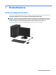
1 Product features Standard configuration features Features may vary depending on the model. For support assistance and to learn more about the hardware and software installed on your computer model, run the HP Support Assistant utility. CAUTION: Several well-known vulnerabilities exist when a computer is in the Sleep state.
Front panel components Drive configuration may vary by model. Some models have a bezel blank covering the optical drive bay. 1 Slim Optical Drive (optional) 6 SD Card Reader (optional) 2 Dual-State Power Button 7 Hard Drive Activity Light 3 USB 2.0 Charging (powered) Port (black) 8 USB 2.0 Port (black) 4 USB 3.
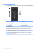
Rear panel components 1 PS/2 Keyboard Connector (purple) 7 PS/2 Mouse Connector (green) 2 DisplayPort Monitor Connectors 8 Serial Connector 3 VGA Monitor Connector 9 RJ-45 Network Connector 4 USB 3.0 Ports (blue) 10 USB 2.0 Ports with Wake from S4/S5 feature (black) 5 Line-Out Connector for powered audio devices (green) 11 Line-In Audio Connector (blue) 6 Power Cord Connector NOTE: An optional second serial port and an optional parallel port are available from HP.
Serial number location Each computer has a unique serial number and a product ID number that are located on the exterior of the computer. Keep these numbers available for use when contacting customer service for assistance.
2 Illustrated parts catalog Microtower (MT) chassis spare parts Computer major components NOTE: HP continually improves and changes product parts. For complete and current information on supported parts for your computer, go to http://partsurfer.hp.com, select your country or region, and then follow the on-screen instructions.
Item Description (1) Access panel (2) Front bezel (3) Power supply 280W, 92% efficient 280W, 85% efficient 280W, standard (4) System board (includes replacement thermal material) (5) Fan sink (includes replacement thermal material) * Memory modules (PC4-17000) 16-GB 8-GB 4-GB * Processors (include replacement thermal material) Intel Core i7-6700 processor Intel Core i5-6600 processor Intel Core i5-6500 processor Intel Core i3-6320 processor Intel Core i3-6300 processor Intel Core i3-6100 proc
Misc parts Item Description (1) Fan (2) Front I/O assembly (3) Solenoid lock (4) Printer port, PCI card (5) NVIDIA GT730 2 GB DDR3 PCIex8 graphics card * AMD Radeon R9 350 2 GB DDR5 PCIe16 graphics card (6) Speaker (7) Secure Digital (SD) card reader (8) SATA data cable, 14 inch, 1 straight end, 1 angled end (9) SATA drive power cable * M.
Item Description * DisplayPort cable * Hard drive conversion bracket, 2.5-inch to 3.5-inch * SATA SS power extension, 20 inch cable * Slim optical drive bezel blank * Hood sensor * HP Business PC Security Lock * Rubber foot * Grommet, hard drive isolation, blue * Wireless antenna for use with WLAN modules * HP UC Speaker Phone * HP Speaker Phone Security Sleeve * Center strip * Adapters PCIe to M.2 adapter with full-sized bracket DisplayPort to HDMI 1.
Item Description HP USB Conferencing Wireless keyboard, mouse, and dongle USB/PS2 Washable Smart card Misc boards Description AMD R9 350 Barfish FH 2 GB GDDR5 PCIe x16 NVIDIA GT730 2 GB DDR3 PCIex8 Intel PRO/1000 NIC Printer port Serial port USB 3.1 Type Cx1 PCIe x1 card PCIe to M.2 adapter WLAN module caddy card + Bluetooth WLAN modules Intel Dual Band Wireless-AC 7265 NV Intel Dual Band Wireless-AC 8260 + Bluetooth 4.0 Intel Dual Band Wireless-AC 3165 + Bluetooth 4.
Drives Description Hard drives 2-TB, 7200-rpm 1-TB, 7200-rpm, 3.5-inch 1-TB, 7200-rpm, 2.5-inch 1-TB, hybrid SSD, 3.5-inch or 2.5-inch 500-GB, 7200-rpm, 2.5-inch, SED 500 GB, 7200 rpm, 3.5-inch or 2.5-inch 500-GB, 7200-rpm, 2.5-inch, OPAL2, self-encrypting drive (SED) 500-GB, 5400-rpm, 2.5-inch, FIPS 500-GB, hybrid SSD, 2.5-inch or 2.5-inch 500-GB, 5400-rpm, 2.5-inch, 5 mm Solid-state drives 512 GB Solid-state Drive (SSD) 512-GB Solid-state Drive (SSD), M.
3 Routine care, SATA drive guidelines, and disassembly preparation This chapter provides general service information for the computer. Adherence to the procedures and precautions described in this chapter is essential for proper service. CAUTION: When the computer is plugged into an AC power source, voltage is always applied to the system board. You must disconnect the power cord from the power source before opening the computer to prevent system board or component damage.
Preventing electrostatic damage to equipment Many electronic components are sensitive to ESD. Circuitry design and structure determine the degree of sensitivity. The following packaging and grounding precautions are necessary to prevent damage to electric components and accessories. ● To avoid hand contact, transport products in static-safe containers such as tubes, bags, or boxes. ● Protect all electrostatic parts and assemblies with conductive or approved containers or packaging.
Recommended materials and equipment Materials and equipment that are recommended for use in preventing static electricity include: ● Antistatic tape ● Antistatic smocks, aprons, or sleeve protectors ● Conductive bins and other assembly or soldering aids ● Conductive foam ● Conductive tabletop workstations with ground cord of one-megohm +/- 10% resistance ● Static-dissipative table or floor mats with hard tie to ground ● Field service kits ● Static awareness labels ● Wrist straps and footwea
● Never cover the ventilation slots on the monitor with any type of material. ● Install or enable power management functions of the operating system or other software, including sleep states. Routine care General cleaning safety precautions 1. Never use solvents or flammable solutions to clean the computer. 2. Never immerse any parts in water or cleaning solutions; apply any liquids to a clean cloth and then use the cloth on the component. 3.
● If you remove a key, use a specially designed key puller to prevent damage to the keys. This tool is available through many electronic supply outlets. CAUTION: Never remove a wide leveled key (like the space bar) from the keyboard. If these keys are improperly removed or installed, the keyboard may not function properly. ● Cleaning under a key may be done with a swab moistened with isopropyl alcohol and squeezed out. Be careful not to wipe away lubricants necessary for proper key functions.
Screws The screws used in the computer are not interchangeable. They may have standard or metric threads and may be of different lengths. If an incorrect screw is used during the reassembly process, it can damage the unit. HP strongly recommends that all screws removed during disassembly be kept with the part that was removed, then returned to their proper locations. CAUTION: Metric screws have a black finish. U.S. screws have a silver finish and are used on hard drives only.
NOTE: Batteries, battery packs, and accumulators should not be disposed of together with the general household waste. In order to forward them to recycling or proper disposal, please use the public collection system or return them to HP, their authorized partners, or their agents. SATA hard drives Serial ATA Hard Drive Characteristics Number of pins/conductors in data cable 7/7 Number of pins in power cable 15 Maximum data cable length 39.
Cable management Always follow good cable management practices when working inside the computer. 18 ● Keep cables away from major heat sources like the heat sink. ● Do not jam cables on top of expansion cards or memory modules. Printed circuit cards like these are not designed to take excessive pressure on them. ● Keep cables clear of sliding or moveable parts to prevent them from being cut or crimped when the parts are moved. ● When folding a flat ribbon cable, never fold to a sharp crease.
4 Removal and replacement procedures – Microtower (MT) chassis Adherence to the procedures and precautions described in this chapter is essential for proper service. After completing all necessary removal and replacement procedures, run the Diagnostics utility to verify that all components operate properly. NOTE: Not all features listed in this guide are available on all computers.
Access panel To access internal components, you must remove the access panel: 1. Prepare the computer for disassembly (Preparation for disassembly on page 19) 2. Pull up the access panel handle (1), and then slide the panel back (2) and lift it off the computer (3). To replace the access panel, reverse the disassembly procedures.
Front bezel 1. Prepare the computer for disassembly (Preparation for disassembly on page 19) 2. Remove the access panel (Access panel on page 20) 3. Lift up the three tabs on the side of the bezel (1), and then rotate the bezel off the chassis (2). To replace the front bezel, reverse the disassembly procedures.
Front bezel security The front bezel can be secured in place by installing a screw through the front of the chassis into the front bezel. 22 1. Prepare the computer for disassembly (Preparation for disassembly on page 19) 2. Remove the access panel (Access panel on page 20) 3. Install a 6-32 screw through the front of the chassis and into the screw hole located below the center bezel release tab. 4. Replace the computer access panel. 5.
Slim optical drive bezel blank On some models, there is a bezel blank covering the slim optical drive bay. Remove the bezel blank before installing an optical drive. To remove the bezel blank: 1. Remove the access panel (Access panel on page 20) 2. Remove the front bezel (Front bezel on page 21) 3. To remove the bezel blank, press upward on the bottom tab and press downward on the top tab on the side of the blank (1), and then rotate the blank off the front of the bezel (2).
Memory Description 16-GB, PC4-17000 8-GB, PC4-17000 4-GB, PC4-17000 The computer comes with double data rate 4 synchronous dynamic random access memory (DDR4-SDRAM) dual inline memory modules (DIMMs). DIMMs The memory sockets on the system board can be populated with up to four industry-standard DIMMs. These memory sockets are populated with at least one preinstalled DIMM.
● The system will operate in single channel mode if the DIMM sockets are populated in one channel only. ● The system will operate in a higher-performing dual channel mode if the total memory capacity of the DIMMs in Channel A is equal to the total memory capacity of the DIMMs in Channel B. The technology and device width can vary between the channels. For example, if Channel A is populated with two 1-GB DIMMs and Channel B is populated with one 2-GB DIMM, the system will operate in dual channel mode.
3. Open both latches of the memory module socket (1), and insert the memory module into the socket (2). NOTE: A memory module can be installed in only one way. Match the notch on the module with the tab on the memory socket. Populate the black DIMM sockets before the white DIMM sockets. For maximum performance, populate the sockets so that the memory capacity is spread as equally as possible between Channel A and Channel B. 4.
Expansion cards Description nVIDIA GT730 2 GB DDR3 PCIex8 AMD Radeon R9 350 2 GB DDR5 PCIe16 graphics card USB 3.1 Type Cx1 PCIe x1 card Printer port, PCI card Serial port, PCI card PCIe to M.2 adapter Intel PRO/1000 NIC WLAN 802.11 (7265NV) a/b/g/n 2x2 + Bluetooth 4.0 module WLAN 802.11 (7265AN) a/b/g/n 2x2 WLAN module caddy card + Bluetooth M.2 USB cable Wireless antenna for use with WLAN modules The computer has three PCI Express x1 expansion sockets and one PCI Express x16 expansion socket.
3. Release the slot cover retention latch that secures the slot covers by lifting the tab on the latch and rotating the latch to the open position. 4. Locate the correct vacant expansion socket on the system board and the corresponding expansion slot on the back of the computer chassis. 5. Before installing an expansion card, remove the expansion slot cover or the existing expansion card.
b. If you are removing a PCI Express x1 card, hold the card at each end and carefully rock it back and forth until the connectors pull free from the socket. Lift the card straight up (1) then away from the inside of the chassis (2) to remove it. Be sure not to scrape the card against other components. c.
8. To install a new expansion card, hold the card just above the expansion socket on the system board then move the card toward the rear of the chassis (1) so that the bottom of the bracket on the card slides into the small slot on the chassis. Press the card straight down into the expansion socket on the system board (2). NOTE: When installing an expansion card, press firmly on the card so that the whole connector seats properly in the expansion card socket. 9.
Drives Description Hard drives 2-TB, 7200-rpm 1-TB, 7200-rpm, 3.5-inch 1-TB, 7200-rpm, 2.5-inch 1-TB, hybrid SSD, 3.5-inch or 2.5-inch 500-GB, 7200-rpm, 2.5-inch, SED 500 GB, 7200 rpm, 3.5-inch or 2.5-inch 500-GB, 7200-rpm, 2.5-inch, OPAL2, self-encrypting drive (SED) 500-GB, 5400-rpm, 2.5-inch, FIPS 500-GB, hybrid SSD, 2.5-inch or 2.5-inch 500-GB, 5400-rpm, 2.5-inch, 5 mm Solid-state drives 512 GB Solid-state Drive (SSD) 512-GB Solid-state Drive (SSD), M.
Description DVD-ROM drive Grommet, hard drive isolation, blue When installing drives, follow these guidelines: ● The primary Serial ATA (SATA) hard drive must be connected to the dark blue primary SATA connector on the system board labeled SATA0. ● Connect secondary hard drives and optical drives to one of the light blue SATA connectors on the system board (labeled SATA1 and SATA2).
Drive positions 1 9.5mm slim optical drive bay 2 3.5-inch secondary hard drive bay 3 3.5-inch primary hard drive bay NOTE: The drive configuration on your computer may be different than the drive configuration shown above. To verify the type and size of the storage devices installed in the computer, run Computer Setup. Removing a 9.5 mm slim optical drive 1. Prepare the computer for disassembly (Preparation for disassembly on page 19) 2. Remove the access panel (Access panel on page 20) 3.
5. Disconnect the power cable (1) and data cable (2) from the rear of the optical drive. CAUTION: When removing the cables, pull the tab or connector instead of the cable itself to avoid damaging the cable. 6. 34 Press upward on the green release latch on the underside of the drive (1), and then slide the drive out of the drive bay (2).
Installing a 9.5 mm slim optical drive 1. Prepare the computer for disassembly (Preparation for disassembly on page 19). 2. Remove the access panel (Access panel on page 20). 3. If you are installing a slim optical drive in a bay covered by a bezel blank, remove the front bezel and then remove the bezel blank. See Front bezel on page 21 for more information. 4. Follow the instructions for removing the optical drive if one was installed. Refer to Removing a 9.5 mm slim optical drive on page 33. 5.
7. Connect the power cable (1) and data cable (2) to the rear of the optical drive. 8. If installing a new drive, connect the opposite end of the data cable to one of the light blue SATA connectors (labeled SATA1 or SATA2) on the system board. 9. Replace the front bezel if it was removed. 10. Replace the computer access panel. 11. Reconnect the power cord and any external devices, and then turn on the computer. 12. Lock any security devices that were disengaged when the access panel was removed.
Removing a hard drive NOTE: Before you remove the old hard drive, be sure to back up the data from the old hard drive so that you can transfer the data to the new hard drive. 1. Prepare the computer for disassembly (Preparation for disassembly on page 19). 2. Remove the access panel (Access panel on page 20). 3. Disconnect the power cable (1) and data cable (2) from the rear of the hard drive. 4. Pull the green latch next to the drive outward (1) and slide the drive out of the bay (2).
Installing a hard drive 38 1. Prepare the computer for disassembly (Preparation for disassembly on page 19). 2. Remove the access panel (Access panel on page 20). 3. You can install a 3.5-inch hard drive or a 2.5-inch hard drive with a 3.5-inch adapter bracket similar to the example shown below. ● Slide the 2.5-inch drive into the bay adapter bracket, ensuring the connector on the drive is fully inserted into the connector on the adapter bracket.
4. Install four mounting screws into the sides of the 3.5-inch drive or the 2.5-inch drive adapter bracket (two on each side). NOTE: HP has supplied four extra mounting screws installed on the chassis next to the hard drive bays. Refer to Drives on page 31 for an illustration of the location of the extra mounting screws. 5. Slide the drive into the drive bay, making sure to align the mounting screws with the guide slots, until the drive snaps into place.
6. Connect the power cable (1) and data cable (2) to the rear of the hard drive. 7. If installing a new drive, connect the opposite end of the data cable to the appropriate system board connector. NOTE: You must connect the primary hard drive data cable to the dark blue connector labeled SATA0 to avoid any hard drive performance problems. If you are adding a second hard drive, connect the data cable to one of the light blue SATA connector labeled SATA1 and SATA2. 8. Replace the computer access panel.
Drive power cable 1. Prepare the computer for disassembly (Preparation for disassembly on page 19). 2. Remove the computer access panel (Access panel on page 20). 3. Remove the cable from the clips on the base pan and on the side of the hard drive cage (1). 4. Disconnect the cable from the hard drive (2) and the optical drive (3) 5. Disconnect the cable from the system board connector labeled SATAPWR0 (4), and then remove the cable from the computer.
Front I/O and power switch assembly 42 1. Prepare the computer for disassembly (Preparation for disassembly on page 19). 2. Remove the computer access panel (Access panel on page 20). 3. Remove the front bezel (Front bezel on page 21). 4. Remove the Torx T15 screw (1) that secures the assembly to the chassis, push the tab on the right side of the assembly (2) to disengage it from the chassis, and push the assembly into the chassis (3). 5. Remove the cables from the clips on the base pan.
6. Disconnect the four cables from the following system board connectors: (1): Front USB (yellow) (2): Front AUD (blue) (3): Front USB3.0 (blue) (4): PB/LED (black) 7. Remove the assembly from the inside of the computer. To reinstall the assembly, reverse the removal procedure.
Fan sink CAUTION: The bond between the fan sink and the processor may be very tight. If the computer will power on, before removing the fan sink, turn on the computer until it warms the fan sink. Warming the fan sink lessens the bond between the heat sink and the processor, thereby making separating them easier. Make sure not to pull the processor out of the socket when you lift the fan sink, especially if you cannot warm the fan sink prior to removal.
Processor Description Intel Core i7-6700 processor Intel Core i5-6600 processor Intel Core i5-6500 processor Intel Core i3-6320 processor Intel Core i3-6300 processor Intel Core i3-6100 processor Intel Pentium G4520 processor Intel Pentium G4500 processor Intel Pentium G4400 processor Intel Celeron G3920 processor Intel Celeron G3900 processor 1. Prepare the computer for disassembly (Preparation for disassembly on page 19). 2. Remove the access panel (Access panel on page 20). 3.
6. Lift the processor (3) straight up and remove it. CAUTION: Do NOT handle the pins in the processor socket. These pins are very fragile and handling them could cause irreparable damage. Once pins are damaged it may be necessary to replace the system board. The heat sink must be installed within 24 hours of installing the processor to prevent damage to the processor’s solder connections. Reverse the removal procedure to install a new processor.
Speaker 1. Prepare the computer for disassembly (Preparation for disassembly on page 19). 2. Remove the access panel (Access panel on page 20). 3. Disconnect the speaker wire from the system board connector labeled SPKR (1). 4. From the inside of the chassis, remove the silver Torx T15 screw (2) that secures the speaker to the chassis. 5. Remove the speaker from the chassis (3). To replace the speaker, reverse the removal procedures.
Rear chassis fan 1. Prepare the computer for disassembly (Preparation for disassembly on page 19). 2. Remove the access panel (Access panel on page 20). 3. Remove the three silver Phillips screws that secure the fan to the rear of chassis. 4. Disconnect the fan control cable (1) from the system board connector labeled CHFAN2. 5. Lift the fan out of the chassis (2). To install the fan assembly, reverse the removal procedure. Be sure to orient the air flow out of the unit.
Power supply Description Power supply, 280W, 92% efficient Power supply, 280W, 85% efficient Power supply, 280W, standard 1. Prepare the computer for disassembly (Preparation for disassembly on page 19). 2. Remove the access panel (Access panel on page 20). 3. Remove the four silver Torx T15 screws that connect the power supply to the rear of the chassis. 4. Remove the power cable from the clip on the base pan.
5. Disconnect the power supply cable from the following system board connectors: (1): PWR (2): PWRCMD (3): PWRCPU 6. Press the tab (1) on the base pan in front of the power supply that holds it in place. 7. Slide the power supply toward the front of the computer, rotate toward the fan so the power supply clears the lip on the top of the chassis, and then lift the power supply out of the chassis (2). To install the power supply, reverse the removal procedure.
System board 1. Prepare the computer for disassembly (Preparation for disassembly on page 19). 2. Remove the access panel (Access panel on page 20). 3. When replacing the system board, make sure the following components are removed from the defective system board and installed on the replacement system board: ● Memory modules (Memory on page 24) ● Expansion cards (Expansion cards on page 27) ● Heat sink (Fan sink on page 44). ● Processor (Processor on page 45) 4.
System board callouts 52 Sys Bd Label Color Component Sys Bd Label Color Component X1PCIEXP3 Black Expansion card PWRCMD White Power supply X1PCIEXP2 Black Expansion card SATAPWR0 Black Drives X1PCIEXP1 Black Expansion card PWR White 6-pin main power X16PCIEXP White Expansion card SPKR White Speaker COMB Black Optional second serial port FRONT USB3.
XU1 Black Processor FRONT USB Yellow Front I/O CPUFAN White Processor fan SATA2 Light blue Any SATA Device other than the primary hard drive DIMM4 White Memory module PSWD Green Clear system passwords DIMM3 Black Memory module CMOS Yellow Reset CMOS DIMM2 White Memory module BATTERY Black RTC battery DIMM1 Black Memory module HSENSE White Hood sensor PB/LED Black Front I/O/power switch FRONT AUD Blue Front I/O System board 53
5 Computer Setup (F10) Utility Computer Setup (F10) Utilities Use Computer Setup (F10) Utility to do the following: ● Change settings from the defaults or restore the settings to default values. ● View the system configuration, including settings for processor, graphics, memory, audio, storage, communications, and input devices. ● Modify the boot order of bootable devices such as hard drives, optical drives, or USB flash media devices.
4. Use the arrow (left and right) keys to select the appropriate heading. Use the arrow (up and down) keys to select the option you want, then press Enter. To return to the Computer Setup Utilities menu, press Esc. 5. To apply and save changes, select Main > Save Changes and Exit. ● If you have made changes that you do not want applied, select Ignore Changes and Exit. ● To restore settings from the Advanced and Main menus to original values, select Apply Factory Defaults and Exit.
Computer Setup–Main NOTE: Support for specific Computer Setup options may vary depending on the hardware configuration. Table 5-1 Computer Setup—Main Option Description System Information Lists all information in following list if Advanced System Information is selected. Lists smaller subset if Basic System Information is selected.
Table 5-1 Computer Setup—Main (continued) ● Lock BIOS Version If this option is checked, the system is locked to the current BIOS version and updates are not allowed. ● BIOS Update Preferences Allows the administrator to select the source of network updates (www.hp.
Computer Setup—Security NOTE: Support for specific Computer Setup options may vary depending on the hardware configuration. Table 5-2 Computer Setup—Security Option Description Set up BIOS Administrator Password Lets you set and enable a BIOS administrator password, which includes the following privileges: ● Manage other BIOS users ● Full access to BIOS policy and settings ● Unlock the computer when other BIOS users fail the preboot authentication.
Table 5-2 Computer Setup—Security (continued) ● Data Recovery Policy Select ‘Automatic’ or ‘Manual’ to set data recovery policy. ‘Manual’ lets you select whether or not to execute recovery of a corrupted region if it is detected. Set Up BIOS Power-On Password Lets you set and enable a BIOS power-on password. The power-on password prompt appears after a power cycle or reboot. If the user does not enter the correct power-on password, the unit will not boot.
Table 5-2 Computer Setup—Security (continued) Default is ‘Unlock’. Cover Removal Sensor (Disabled/Notify user/Administrator password) Lets you disable the cover sensor or configure what action is taken if the computer cover was removed. Default is ‘Disabled’. NOTE: Notify user alerts the user with a POST error on the first boot after the sensor detects removal of the cover.
Table 5-3 Computer Setup—Advanced (for advanced users) (continued) ● Legacy Boot Order Specify the order in which legacy boot sources (such as a network interface card, internal hard drive, USB optical drive, or internal optical drive) are checked for a bootable operating system image. Specify the order of attached hard drives. The first hard drive in the order will have priority in the boot sequence and will be recognized as drive C (if any devices are attached).
Table 5-3 Computer Setup—Advanced (for advanced users) (continued) Virtualization Technology for Directed I/O (VTd) (Intel only) Controls virtualization DMA remapping features of the chipset. Changing this setting requires turning the computer off and then back on. Default is disabled. PCI Express Slot x (enable/disable) Lets you disable individual expansion slots.
Table 5-3 Computer Setup—Advanced (for advanced users) (continued) ● Serial port B ● SATA0 ● SATA1 ● SATA2 ● SATA3 ● SATA5 ● Front USB ports ● Rear USB ports ● USB charging port function ● Media card reader Restrict USB Devices Specify the following categories of USB devices to enable: ● Allow all USB devices ● Allow only keyboard and mouse ● Allow all but storage devices and hubs.
Table 5-3 Computer Setup—Advanced (for advanced users) (continued) This feature is designed to provide a visual indication of what sleep state the system is in. Each sleep state has a unique blink pattern. Default is disabled. NOTE: A normal shutdown goes to the S4 state for Windows 8 or later. S0 (On) = Solid white LED. S3 (Stand By)= 3 blinks at 1Hz (50% duty cycle) followed by a pause of 2 seconds (white LED) — repeated cycles of 3 blinks and a pause.
Recovering the Configuration Settings This method of recovery requires that you first perform the Save to Removable Media command with the Computer Setup (F10) Utility before Restore is needed. (See Computer Setup–Main on page 56 in the Computer Setup—File table.) The Save to Removable Media option creates a file named HPSETUP.TXT on an inserted USB flash media device. This file can be edited to change the settings on Restore. An asterisk (*) marks the selected option for a setting.
6 Troubleshooting without diagnostics This chapter provides information on how to identify and correct minor problems, such as USB devices, hard drive, optical drive, graphics, audio, memory, and software problems. If you encounter problems with the computer, refer to the tables in this chapter for probable causes and recommended solutions.
If it becomes necessary to call for technical assistance, be prepared to do the following to ensure that your service call is handled properly: ● Be in front of your computer when you call. ● Write down the computer serial number, product ID number, and monitor serial number before calling. ● Spend time troubleshooting the problem with the service technician. ● Remove any hardware that was recently added to your system. ● Remove any software that was recently installed.
● If you have installed an operating system other than the factory-installed operating system, check to be sure that it is supported on the system. ● If the system has multiple video sources (embedded, PCI, or PCI-Express adapters) installed (embedded video on some models only) and a single monitor, the monitor must be plugged into the monitor connector on the source selected as the primary VGA adapter.
Computer date and time display is incorrect. Cause Solution RTC (real-time clock) battery may need to be replaced. Reset the date and time under Control Panel (Computer Setup can also be used to update the RTC date and time). If the problem persists, replace the RTC battery. See the Removal and Replacement section for instructions on installing a new battery, or contact an authorized dealer or reseller for RTC battery replacement.
Poor performance. Cause Solution 3. Make sure the processor heat sink is installed properly. Hard drive is full. Transfer data from the hard drive to create more space on the hard drive. Low on memory. Add more memory. Hard drive fragmented. Defragment hard drive. Program previously accessed did not release reserved memory back to the system. Restart the computer. Virus resident on the hard drive. Run virus protection program. Too many applications running. 1.
Computer powered off automatically and the Power LED flashes red four times and then white two times. Cause Solution Processor thermal protection activated: 1. Ensure that the computer air vents are not blocked and the processor cooling fan is running. 2. Open the access panel, press the power button, and see if the processor fan (or other system fan) spins. If the fan does not spin, make sure the fan cable is plugged onto the system board header. 3. If fan a plugged in and not spinning, replace it.
Solving power problems Common causes and solutions for power problems are listed in the following table. Power supply shuts down intermittently. Cause Solution If equipped with a voltage selector, voltage selector switch on rear of computer chassis (some models) not switched to correct line voltage (115V or 230V). Select the proper AC voltage using the selector switch. Power supply will not turn on because of internal power supply fault. Replace the power supply.
Solving hard drive problems Hard drive error occurs. Cause Solution Hard disk has bad sectors or has failed. 1. In Windows 7, click Start, click Computer, and right-click on a drive. Select Properties, and then select the Tools tab. Under Error-checking click Check Now. In Windows 8.1, on the Start screen type e, and then select File Explorer from the list of applications. In the left column, expand Computer, right-click on a drive, select Properties, and then select the Tools tab.
Drive not found (identified). Cause Solution The device is attached to a SATA port that has been hidden in Computer Setup. Run the Computer Setup utility and ensure Device Available is selected for the device's SATA port in Advanced > Port Options. Drive responds slowly immediately after power-up. Run Computer Setup and increase the POST Delay in Advanced > Boot Options. Nonsystem disk/NTLDR missing message.
Computer seems to be locked up. Cause Solution Program in use has stopped responding to commands. 1. Use the task manager to close programs that do not respond. 2. Attempt the normal Windows “Shut Down” procedure. If this fails, press the power button for four or more seconds to turn off the power. To restart the computer, press the power button again. Solving media card reader problems Media card will not work in a digital camera after formatting it in Windows.
Do not know how to remove a media card correctly. Cause Solution The computer’s software is used to safely eject the card. In Windows 7, click Start, select Computer, right-click on the corresponding drive icon, and then select Eject. Pull the card out of the slot. In Windows 8.1, on the Start screen, type e, and then click File Explorer from the list of applications. Expand Computer, rightclick on the corresponding drive icon, and then select Eject. Pull the card out of the slot.
Blank screen (no video). Cause Solution You may have a screen blanking utility installed or energy saver features are enabled. Press any key or click the mouse button and type your password (if set). System ROM is corrupted; system is running in Boot Block Emergency Recovery Mode (indicated by eight beeps). Reflash the system ROM with the latest BIOS image. You are using a fixed-sync monitor and it will not sync at the resolution chosen.
Blank screen and the power LED flashes Red six times, once every second, followed by a two second pause, and the computer beeps six times. (Beeps stop after fifth iteration but LEDs continue flashing.) Cause Solution Pre-video graphics error. For systems with a graphics card: 1. Reseat the graphics card (if applicable). Power on the system. 2. Replace the graphics card (if applicable). 3. Replace the system board. For systems with integrated graphics, replace the system board.
The picture is broken up, rolls, jitters, or flashes. Cause Solution The monitor connections may be incomplete or the monitor may be incorrectly adjusted. 1. Be sure the monitor cable is securely connected to the computer. 2. In a two-monitor system or if another monitor is in close proximity, be sure the monitors are not interfering with each other’s electromagnetic field by moving them apart. 3. Fluorescent lights or fans may be too close to the monitor. Monitor needs to be degaussed.
“Out of Range” displays on screen. Cause Solution 1. Press the Windows logo + l to open the Settings charm. 2. Select Change PC Settings, select General, and then under Advanced startup, click Restart now. 3. Select Troubleshoot, select Advanced options, select Startup Settings, and then click Restart. 4. Use the function keys or number keys to select the safe mode option you want. When your computer is in safe mode, Safe Mode displays in the corners of your monitor.
Certain typed symbols do not appear correct. Cause Solution In Windows 7, click Start, select All Programs, select Accessories, select System Tools, and then select Character Map. In Windows 8.1, on the Start screen, type ch, and then select Character Map from the list of applications. In Windows 10, type ch in the taskbar search box, and then select Character Map from the list of applications.
Sound does not come out of the speaker or headphones. Cause Solution The application is set to use a different audio device than speakers. Some graphics cards support audio over the DisplayPort connection (if applicable), so multiple audio devices may be listed in Device Manager. Make sure the correct device is being used. To access Device Manager in Windows 7, click Start, select Control Panel, and then select Device Manager. To access Device Manager in Windows 8.
There is no sound or sound volume is too low. Cause Solution To access Device Manager in Windows 8.1, from the Start screen, type c, select Control Panel from the list of applications, and then select Device Manager. To access Device Manager in Windows 10, type device manager in the taskbar search box, and then select Device Manager from the list of applications. Some applications can select which audio output device is used. Make sure the application has selected the correct audio device.
Printer prints garbled information. Cause Solution The cables may not be connected properly. Reconnect all cables. Printer memory may be overloaded. Reset the printer by turning it off for one minute, then turn it back on. Printer will not print. Cause Solution The printer may be out of paper. Check the paper tray and refill it if it is empty.
Mouse does not respond to movement or is too slow. Cause Solution 1. Press the Ctrl and Esc keys at the same time (or press the Windows logo key) to display the Start menu. 2. Use the arrow keys to select Shut Down and then press Enter. 3. After the shutdown is complete, plug the mouse connector into the back of the computer (or the keyboard) and restart. Windows 8.1: 1. Press the Windows logo + l to open the Settings charm. 2. Use the arrow keys to select Power, and then press Enter. 3.
Solving Hardware Installation Problems You may need to reconfigure the computer when you add or remove hardware, such as an additional drive or expansion card. If you install a plug and play device, Windows automatically recognizes the device and configures the computer. If you install a non-plug and play device, you must reconfigure the computer after completing installation of the new hardware. In Windows, use the Add Hardware Wizard and follow the instructions that appear on the screen.
Computer will not start. Cause Solution NOTE: DIMM1 or XMM1 must always be installed. DIMM1 must be installed before DIMM2, and DIMM3 must be installed before DIMM4. 2. Observe the beeps and LED lights on the front of the computer. Beeps and flashing LEDs are codes for specific problems. 3. If you still cannot resolve the issue, contact Customer Support. Power LED flashes Red three times and then white two times. Cause Solution Memory is installed incorrectly or is bad.
Table 6-2 Solving Network Problems (continued) Network driver does not detect network controller. Cause Solution To access Device Manager in Windows 10, type device manager in the taskbar search box, and then select Device Manager from the list of applications. Incorrect network driver. Check the network controller documentation for the correct driver or obtain the latest driver from the manufacturer’s Web site. Network status link light never flashes.
Diagnostics reports a failure. Cause Solution The cable is not securely connected. Ensure that the cable is securely attached to the network connector and that the other end of the cable is securely attached to the correct device. The cable is attached to the incorrect connector. Ensure that the cable is attached to the correct connector. There is a problem with the cable or a device at the other end of the cable. Ensure that the cable and device at the other end are operating correctly.
New network card will not boot. Cause Solution New network card may be defective or may not meet industrystandard specifications. Install a working, industry-standard NIC, or change the boot sequence to boot from another source. Cannot connect to network server when attempting Remote System Installation. Cause Solution The network controller is not configured properly.
Out of memory error. Cause Solution You have run out of memory to run the application. Check the application documentation to determine the memory requirements. Memory count during POST is wrong. Cause Solution The memory modules may not be installed correctly. Check that the memory modules have been installed correctly and that proper modules are used. Integrated graphics may use system memory. No action required. Insufficient memory error during operation.
System will not boot from CD-ROM or DVD drive. Cause Solution Non-bootable CD in drive. Try a bootable CD in the drive. Boot order not correct. Run the Computer Setup utility and change boot sequence in Advanced > Boot Options. Drive not found (identified). Cause Solution Cable could be loose. Check cable connections. The system may not have automatically recognized a newly installed device. See reconfiguration directions in the Solving Hardware Installation Problems on page 86 section.
Cannot eject compact disc (tray-load unit). Cause Solution Disc not properly seated in the drive. Turn off the computer and insert a thin metal rod into the emergency eject hole and push firmly. Slowly pull the tray out from the drive until the tray is fully extended, then remove the disc. CD-ROM, CD-RW, DVD-ROM, or DVD-R/RW drive cannot read a disc or takes too long to start. Cause Solution Media is corrupt. Try different media to confirm whether media is valid. Media has been inserted upside down.
Solving USB flash drive problems If you encounter USB flash drive problems, common causes and solutions are listed in the following table. USB flash drive is not seen as a drive letter in Windows. Cause Solution The drive letter after the last physical drive is not available. Change the default drive letter for the flash drive in Windows. USB flash drive not found (identified). Cause Solution The device is attached to a USB port that has been hidden in Computer Setup.
Solving front panel component problems If you encounter problems with devices connected to the front panel, refer to the common causes and solutions listed in the following table. A USB device, headphone, or microphone is not recognized by the computer. Cause Solution Device is not properly connected. 1. Turn off the computer. 2. Reconnect the device to the front of the computer and restart the computer. The device does not have power.
Unable to connect to the Internet. Cause Solution 3. In the Browsing history section on the General tab, click the Delete button. 4. Select the Cookies check box and click the Delete button. Windows 8.1: 1. From the Start screen, type c, and then select Control Panel from the list of applications. 2. Click Internet Options. 3. In the Browsing history section on the General tab, click the Delete button. 4. Select the Cookies check box and click the Delete button. Windows 10: 1.
Solving software problems Most software problems occur as a result of the following: ● The application was not installed or configured correctly. ● There is insufficient memory available to run the application. ● There is a conflict between applications. ● Be sure that all the needed device drivers have been installed. ● If you have installed an operating system other than the factory-installed operating system, check to be sure it is supported on the system.
7 POST error messages and diagnostic front panel LEDs and audible codes This appendix lists the error codes, error messages, and the various indicator light and audible sequences that you may encounter during Power-On Self-Test (POST) or computer restart, the probable source of the problem, and steps you can take to resolve the error condition. POST Message Disabled suppresses most system messages during POST, such as memory count and nonerror text messages.
Control panel message 008–Microcode Patch Error 009–PMM Allocation Error during MEBx Download Description Recommended action RTC (real-time clock) battery may need to be replaced. problem persists, replace the RTC battery. See the Removal and Replacement section for instructions on installing a new battery. Processor is not supported by the BIOS. 1. Upgrade BIOS to proper version. 2. Change the processor. 1. Reboot the computer. 2.
Control panel message Description Recommended action 00E-Inventory Error during MEBx Execution BIOS information passed to the MEBx resulted in a failure. 1. Reboot the computer. 2. If the error persists, update to the latest BIOS version. 3. If the error still persists, replace the system board. 1. Reboot the computer. 2. If the error persists, update to the latest BIOS version. 3. If the error still persists, replace the system board.
Control panel message 302-Hard Disk 2: SMART Hard Drive Detects Imminent Failure 309 – 30C: Hard Disk 3–6: SMART Hard Drive Detects Imminent Failure Description Recommended action Hard drive is about to fail. (Some hard drives have a hard drive firmware patch that will fix an erroneous error message.) Hard drive is about to fail. (Some hard drives have a hard drive firmware patch that will fix an erroneous error message.) 3. Back up contents and replace hard drive. 1.
Control panel message Description Recommended action 3. Reconfigure card resources and/or run Computer Setup or Windows utilities. If a PCI expansion card was recently added, remove it to see if the problem remains. 419-Out of Memory Space for Option ROMs Recently added PCI expansion card contains an option ROM too large to download during POST. ▲ 41A-Front USB1/USB2 Not Connected Front USB cable has been detached or unseated from system board. Reconnect or replace front USB cable.
Control panel message Description Recommended action 90B-Fan Failure The system has detected that a cooling fan is not operating correctly. 1. Reseat fan. 2. Reseat fan cable. 3. Replace fan. 90D-System Temperature Thermal shutdown occurred. The system BIOS has detected your machine was previously shut down to avoid overheating. Overheating may occur if the cooling vents are blocked or the operating temperature exceeds the system specifications.
4 Thermal 5 System board Patterns of blink/beep codes are determined by using the following parameters: ● 1 second pause occurs after the last major blink. ● 2 second pause occurs after the last minor blink. ● Beep error code sequences occur for the first 5 iterations of the pattern and then stop. ● Blink error code sequences continue until the computer is unplugged or the power button is pressed. NOTE: Not all diagnostic lights and audible codes are available on all models.
8 Password security and resetting CMOS This computer supports security password features, which can be established through the Computer Setup Utilities menu. This computer supports two security password features that are established through the Computer Setup Utilities menu: administrator password and power-on password. When you establish only an administrator password, any user can access all the information on the computer except Computer Setup.
1. Shut down the operating system properly, then turn off the computer and any external devices, and disconnect the power cord from the power outlet. 2. With the power cord disconnected, press the power button again to drain the system of any residual power. WARNING! To reduce the risk of personal injury from electrical shock and/or hot surfaces, be sure to disconnect the power cord from the wall outlet, and allow the internal system components to cool before touching.
Clearing and resetting the BIOS The CMOS button resets BIOS settings to default, but does not clear the passwords or affect any of the other Security settings. On Intel systems with advanced manageability features, the CMOS button will also partially unprovision AMT. 1. Turn off the computer and any external devices, and disconnect the power cord from the power outlet. 2. Disconnect the keyboard, monitor, and any other external equipment connected to the computer.
9 Using HP PC Hardware Diagnostics (UEFI) HP PC Hardware Diagnostics is a Unified Extensible Firmware Interface (UEFI) that allows you to run diagnostic tests to determine whether the computer hardware is functioning properly. The tool runs outside the operating system so that it can isolate hardware failures from issues that are caused by the operating system or other software components.
4. Select your computer, and then select your operating system. 5. In the Diagnostic section, follow the on-screen instructions to select and download the UEFI version you want.
10 System backup and recovery Backing up, restoring, and recovering in Windows 10 This section provides information about the following processes. The information in the section is standard procedure for most products. ● Creating recovery media and backups ● Restoring and recovering your system For additional information, refer to Help and Support. ▲ Type help in the taskbar search box, and then select Help and Support.
◦ Only one set of recovery media can be created. Handle these recovery tools carefully, and keep them in a safe place. ◦ HP Recovery Manager examines the computer and determines the required storage capacity for the media that will be required. ◦ To create recovery discs, your computer must have an optical drive with DVD writer capability, and you must use only high-quality blank DVD-R, DVD+R, DVD-R DL, or DVD+R DL discs.
Using Windows tools You can create recovery media, system restore points, and backups of personal information using Windows tools. NOTE: If storage is 32 GB or less, Microsoft System Restore is disabled by default. For more information and steps, see Help and Support. ▲ Type help in the taskbar search box, and then select Help and Support. Restore and recovery There are several options for recovering your system.
IMPORTANT: Recovery through HP Recovery Manager should be used as a final attempt to correct computer issues. ● HP Recovery media must be used if the computer hard drive fails. If you have not already created recovery media, see Creating HP Recovery media (select products only) on page 110. ● To use the Factory Reset option (select products only), you must use HP Recovery media. If you have not already created recovery media, see Creating HP Recovery media (select products only) on page 110.
Changing the computer boot order If your computer does not restart in HP Recovery Manager, you can change the computer boot order, which is the order of devices listed in BIOS where the computer looks for startup information. You can change the selection to an optical drive or a USB flash drive. To change the boot order: 1. Insert the HP Recovery media. 2. Access BIOS. Restart the computer, quickly press esc, and then press f9 for boot options. 3.
1. After you successfully set up the computer, create recovery media. This step creates a backup of the recovery partition on the computer. The backup can be used to reinstall the original operating system in cases where the hard drive is corrupted or has been replaced. You will use a USB flash drive to create a bootable recovery drive that can be used to troubleshoot a computer that is unable to start.
7. Select Reset. 8. Follow the on-screen instructions to continue. Recovery using the Windows recovery USB flash drive To recover your system using the recovery USB flash drive you previously created: NOTE: If you did not create a recovery USB flash drive or the one you created does not work, see Recovery using Windows operating system media (purchased separately) on page 116. 1. If possible, back up all personal files. 2.
This section provides information about the following processes: ● Creating recovery media and backups ● Restoring and recovering your system NOTE: This section describes an overview of backing up, restoring, and recovering options. For more details about the Windows Backup and Restore tools provided, see Help and Support. To access Help and Support, select Start > Help and Support. Recovery after a system failure is only as good as your most recent backup. 1.
● If you are creating recovery discs, be sure to use high-quality discs. It is normal for the system to reject defective discs. You will be prompted to insert a new blank disc to try again. ● The number of discs in the recovery-disc set depends on your computer model (typically 3 to 6 DVDs). The Recovery Media Creation program tells you the specific number of blank discs needed to make the set.
To create recovery discs, your computer must have a DVD writer. Use any of the following types of discs (purchased separately): DVD+R, DVD+R DL, DVD-R, DVD-R DL, or DVD±RW. The discs you use will depend on the type of optical drive you are using. Creating recovery discs NOTE: The Windows 7 operating system DVD can be created only once. The option to create that media will not be available after you create a Windows DVD. To create the Windows DVD: 1.
1. Select Start > All Programs > Maintenance > Backup and Restore. 2. Follow the on-screen instructions to set up your backup. System Restore If you have a problem that might be due to software that you installed on your computer, or if you want to restore the system to a previous state without losing any personal information, use System Restore to return the computer to a previous restore point. NOTE: Always use this System Restore procedure before you use the System Recovery feature.
1. Turn off the computer. 2. Disconnect all peripheral devices from the computer except the monitor, keyboard, and mouse. 3. Turn on the computer. 4. When Windows has loaded, click the Start button, and then click All Programs. ● If Security and Protection is listed, continue with step 5. ● If Productivity and Tools is listed, follow the steps in System Recovery when Windows is not responding on page 121. 5. Click Security and Protection, click Recovery Manager, and then click Recovery Manager.
1. If you are using a set of DVDs, insert the first recovery disc into the DVD drive tray, and close the tray. If you are using a recovery USB flash drive, insert it into a USB port. 2. Click the Start button, and then click Shut Down. or If the computer is not responding, press and hold the power button for approximately 5 seconds or until the computer turns off. 3. Disconnect all peripheral devices from the computer except the monitor, keyboard, and mouse. 4.
1. If possible, back up all personal files. 2. Restart the computer, and then insert the Windows 7 operating system DVD into the optical drive before the Windows operating system loads. NOTE: If the computer does not boot to the DVD, restart the computer and press Esc as the computer is powering on to see the startup menu. Use the arrow keys to select the boot menu and press Enter. Use the arrow keys to select the location where the recovery DVD is inserted. Press Enter to boot from that device. 3.
A Battery replacement The battery installed on the computer provides power to the real-time clock. When replacing the battery, use a battery equivalent to the battery originally installed on the computer. The computer has a 3-volt lithium coin cell battery installed. WARNING! The computer contains an internal lithium manganese dioxide battery. There is a risk of fire and burns if the battery is not handled properly. To reduce the risk of personal injury: Do not attempt to recharge the battery.
b. Slide the replacement battery into position, positive side up. The battery holder automatically secures the battery in the proper position. Type 2 a. To release the battery from its holder, squeeze the metal clamp that extends above one edge of the battery. When the battery pops up, lift it out (1). b. To insert the new battery, slide one edge of the replacement battery under the lip of the holder with the positive side up.
b. Insert the new battery and position the clip back into place. NOTE: After the battery has been replaced, use the following steps to complete this procedure. 8. Replace the computer access panel. 9. Plug in the computer and turn on power to the computer. 10. Reset the date and time, your passwords, and any special system setups using Computer Setup. 11. Lock any security devices that were disengaged when the computer access panel was removed.
B Power Cord Set Requirements The power supplies on some computers have external power switches. The voltage select switch feature on the computer permits it to operate from any line voltage between 100-120 or 220-240 volts AC. Power supplies on those computers that do not have external power switches are equipped with internal switches that sense the incoming voltage and automatically switch to the proper voltage.
Country-Specific Requirements Additional requirements specific to a country are shown in parentheses and explained below. Country Accrediting Agency Country Accrediting Agency Australia (1) EANSW Italy (1) IMQ Austria (1) OVE Japan (3) METI Belgium (1) CEBC Norway (1) NEMKO Canada (2) CSA Sweden (1) SEMKO Denmark (1) DEMKO Switzerland (1) SEV Finland (1) SETI United Kingdom (1) BSI France (1) UTE United States (2) UL Germany (1) VDE 1.
C Statement of Volatility HP confirms that Intel-based business desktop systems contain DDR4 volatile memory (memory amount depends on the customer configuration).
D Specifications MT Specifications Table D-1 Specifications Chassis Height 14.0 in 355 mm Width 6.7 in 170 mm Depth 13.4 in 340 mm Approximate Weight 14.0 lb 6.35 kg Operating 50° to 95°F 10° to 35°C Nonoperating -22° to 140°F -30° to 60°C Temperature Range NOTE: Operating temperature is derated 1.0° C per 300 m (1000 ft) to 3000 m (10,000 ft) above sea level; no direct sustained sunlight. Maximum rate of change is 10° C/Hr.
Table D-1 Specifications (continued) The 280W power supply meets the 5000m requirements of CCC. Rated Input Current 3.6A Current Leakage (NFPA 99) 1 With ground < 100 μA Without ground < 275 μA This system utilizes an active power factor corrected power supply. This allows the system to pass the CE mark requirements for use in the countries of the European Union. The active power factor corrected power supply also has the added benefit of not requiring an input voltage range select switch.
Index A access panel locked 69 removal 20 access panel, MT illustrated 6 administrator password 105 audible codes 103 audio problems 81 B backup and recovery, Windows 7 116 Backup and Restore, Windows 7 119 backups creating Windows 7 117, 119 battery disposal 16 battery replacement 124 beep codes 103 BIOS clearing and resetting 107 booting options Full Boot 98 Quick Boot 98 C cable management 18 cable pinouts, SATA data 17 cautions AC power 11 cables 16 cooling fan 15 electrostatic discharge 11 keyboard cle
HP Recovery Disc Creator, using I installing battery 124 drive cables 31 expansion card 27 hard drive 38 memory 24 optical drive 35 Internet access problems 118 95 K keyboard cleaning 14 keyboard problems 84 L locks front bezel 22 M media card reader problems 75 memory installation 24 problems 90 socket population 24 specifications 24 memory modules illustrated 6 monitor problems 76 mouse cleaning 15 problems 84 MT disassembly preparation 19 heat sink removal and replacement 44 preparation for disassem
safety precautions cleaning 14 SATA connectors on system board 17 data cable pinouts 17 hard drive characteristics 17 SATA data cable illustrated 7 SATA drive cable, MT illustrated 7 screws, correct size 16 security front bezel 22 serial number location 4 serial port illustrated 27 service considerations 15 software problems 97 servicing computer 15 solenoid lock illustrated 7 solid-state drives sizes 10, 31 speaker illustrated 7 removal and replacement 47 specifications computer 130 memory 24 static electr