
HP ProDesk 600 G2 Microtower Business PC - Maintenance and Service Guide


Table Of Contents
- Product features
- Illustrated parts catalog
- Routine care, SATA drive guidelines, and disassembly preparation
- Removal and replacement procedures – Microtower (MT) chassis
- Computer Setup (F10) Utility
- Troubleshooting without diagnostics
- Safety and comfort
- Before you call for technical support
- Helpful hints
- Solving general problems
- Solving power problems
- Solving hard drive problems
- Solving media card reader problems
- Solving display problems
- Solving audio problems
- Solving printer problems
- Solving keyboard and mouse problems
- Solving Hardware Installation Problems
- Solving Network Problems
- Solving memory problems
- Solving CD-ROM and DVD problems
- Solving USB flash drive problems
- Solving front panel component problems
- Solving Internet access problems
- Solving software problems
- POST error messages and diagnostic front panel LEDs and audible codes
- Password security and resetting CMOS
- Using HP PC Hardware Diagnostics (UEFI)
- System backup and recovery
- Battery replacement
- Power Cord Set Requirements
- Statement of Volatility
- Specifications
- Index
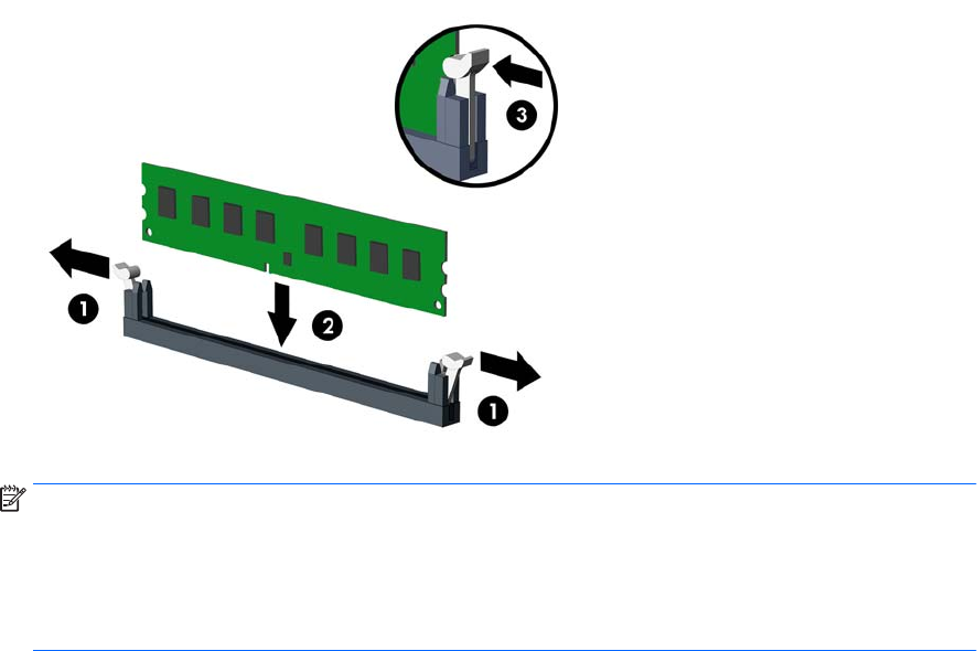
3. Open both latches of the memory module socket (1), and insert the memory module into the socket (2).
NOTE: A memory module can be installed in only one way. Match the notch on the module with the tab
on the memory socket.
Populate the black DIMM sockets before the white DIMM sockets.
For maximum performance, populate the sockets so that the memory capacity is spread as equally as
possible between Channel A and Channel B.
4. Push the module down into the socket, ensuring that the module is fully inserted and properly seated.
Make sure the latches are in the closed position (3).
5. Repeat steps 3 and 4 to install any additional modules.
6. Replace the computer access panel.
7. Reconnect the power cord and turn on the computer.
8. Lock any security devices that were disengaged when the access panel was removed.
The computer should automatically recognize the additional memory the next time you turn on the computer.
26 Chapter 4 Removal and replacement procedures – Microtower (MT) chassis