Hardware Guide HP Compaq Notebook Series Document Part Number: 333955-001 August 2003 This guide explains how to identify and use notebook hardware features, including connectors for external devices. It also includes power and environmental specifications, which may be helpful when traveling with the notebook.
© 2003 Hewlett-Packard Development Company, L.P. Microsoft and Windows are trademarks of Microsoft Corporation in the U.S. and/or other countries. Intel and SpeedStep are trademarks of Intel Corporation in the US and/or other countries. SD Logo is a trademark. The information contained herein is subject to change without notice. The only warranties for HP products and services are set forth in the express warranty statements accompanying such products and services.
Contents 1 Notebook Features Pointing Device Components. . . . . . . . . . . . . . . . . . . . . . 1–1 Top Components . . . . . . . . . . . . . . . . . . . . . . . . . . . . . . . 1–2 Lights . . . . . . . . . . . . . . . . . . . . . . . . . . . . . . . . . . . . . . . . 1–5 Left Side Components . . . . . . . . . . . . . . . . . . . . . . . . . . . 1–7 Right Side Components . . . . . . . . . . . . . . . . . . . . . . . . . . 1–9 Front View Components . . . . . . . . . . . . . . . . . . . . . . . .
Contents Increasing Screen Brightness (fn+f10) . . . . . . . . . . . 2–8 Displaying System Information (fn+esc) . . . . . . . . . 2–9 Using Hotkeys and Shortcut Keys with External Keyboards . . . . . . . . . . . . . . . . . . . . . . . . . . . . . . . . . 2–9 Using Quick Launch Buttons . . . . . . . . . . . . . . . . . . . . . 2–10 Using Keypads . . . . . . . . . . . . . . . . . . . . . . . . . . . . . . . . 2–12 Using the Embedded Numeric Keypad . . . . . . . . . . 2–12 Using an External Keypad. . . . . .
Contents 4 Drives Caring for Drives . . . . . . . . . . . . . . . . . . . . . . . . . . . . . . . 4–1 Adding a Drive to the System . . . . . . . . . . . . . . . . . . . . . 4–3 Hard Drive . . . . . . . . . . . . . . . . . . . . . . . . . . . . . . . . . . . . 4–4 Identifying the Hard Drive Activity Light. . . . . . . . . 4–4 Replacing the Primary Hard Drive . . . . . . . . . . . . . . 4–5 Optical Drive . . . . . . . . . . . . . . . . . . . . . . . . . . . . . . . . . . 4–9 Inserting an Optical Disc . . . .
Contents Connecting a Network Cable . . . . . . . . . . . . . . . . . . . . . . Linking to an Infrared Device . . . . . . . . . . . . . . . . . . . . . Setting Up an Infrared Transmission. . . . . . . . . . . . . Using Standby with Infrared . . . . . . . . . . . . . . . . . . . 6–4 6–5 6–6 6–6 7 External Devices Connecting a Monitor or Projector . . . . . . . . . . . . . . . . . Using a USB Device . . . . . . . . . . . . . . . . . . . . . . . . . . . . Enabling USB Legacy Support . . . . . . . . . . . .
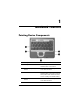
1 Notebook Features Pointing Device Components Component Description 1 Pointing stick Moves the pointer and selects or activates items on the screen. 2 Left and right pointing stick buttons Function like the left and right buttons on an external mouse. 3 TouchPad Moves the pointer and selects or activates items on the screen. Can be set to perform other mouse functions, such as scrolling and double-clicking.
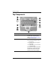
Notebook Features Top Components Component Description 1 Quick Launch buttons (3) Enable you to access common functions with a single keystroke. Refer to “Using Quick Launch Buttons,” in Chapter 2 of this guide. 2 Power button When the notebook is: ■ Off, press and release to turn on the notebook. ■ In Standby, press and release to exit Standby. ■ In Hibernation, press and release to exit Hibernation.
Notebook Features Component Description ✎ This table describes default settings. For information about changing the functions of the power button and using Standby and Hibernation, refer on the Documentation Library CD to the Software Guide, “Power” chapter. 3 fn key Executes frequently used system functions when pressed in combination with a function key or the esc key. 4 Microsoft logo key Displays the Windows Start menu.
Notebook Features 9 1–4 Component Description Display latch recess Secures the display when the notebook is closed. Memory compartment (not shown; located under the keyboard) Contains one primary memory module slot (populated) and one expansion slot.
Notebook Features Lights Component Description 1 Num lock On: Num lock is on or the embedded numeric keypad is enabled. 2 Caps lock On: Caps lock is on. 3 Scroll lock On: Scroll lock is on. 4 Wireless On/Off On: An integrated wireless device has been enabled. 5 Power/Standby On: Power is turned on. Blinking: Notebook is in Standby. ✎ The power/standby light also blinks when a battery pack that is the only available power source reaches a critical low-battery condition.
Notebook Features Component Description 6 Battery On: A battery pack is charging. Blinking: A battery pack that is the only available power source has reached a low-battery condition. When the battery reaches a critical low-battery condition, the battery light begins blinking more quickly. 7 Drive On: One of the following integrated drives is being accessed: ■ Hard drive ■ Optical drive 8 1–6 MultiBay On: A drive in the MultiBay is being accessed.
Notebook Features Left Side Components 1 Component Description Security cable slot Attaches an optional security cable to the notebook. Ä 2 Exhaust vent Enables airflow to cool internal components. Ä 3 Optical disc drive The purpose of security solutions is to act as a deterrent. These solutions do not prevent the product from being mishandled or stolen. To prevent overheating, do not obstruct vents.
Notebook Features 1–8 Component Description 4 Optical disc drive eject button Opens the optical disc drive when pressed. 5 Battery bay Holds the primary battery pack. Battery pack ships outside the notebook.
Notebook Features Right Side Components Component Description 1 PC Card eject buttons (2) Eject an optional PC Card or Smart Card (if a Smart Card Reader is installed) from the top or bottom PC Card slot. 2 PC Card slots (2) Support optional Type I, Type II, or Type III 32-bit (CardBus) or 16-bit PC Cards. ✎ In select notebooks, one PC Card slot may be replaced with a factory-installed Smart Card Reader. 3 Secure Digital (SD) slot Accepts SD memory card.
Notebook Features Component Description 5 RJ-11 jack Connects a modem cable. 6 Audio line-out jack Connects optional powered stereo speakers, headphones, headset, or television audio. 7 Microphone jack Connects an optional monaural microphone. 8 MultiBay Supports an optional MultiBay device, such as a drive or battery pack. 9 Bluetooth compartment Holds a Bluetooth device. ✎ 1–10 Bluetooth is not available in all countries.
Notebook Features Front View Components Component Description 1 Speakers (2) Produce system sound. 2 Display release latch Opens the notebook. 3 Mute button Mutes the system volume. The button lights up when volume is muted. 4 Volume control buttons Increase and decrease system volume. Press the volume up button (on right) to increase sound. Press the volume down button (on left) to decrease sound. 5 Wireless antennae (2) Transmit wireless data. Å Exposure to Radio Frequency Radiation.
Notebook Features Rear Panel Components I Component Description 1 USB connector Connects USB 1.1- and 2.0-compliant devices to the notebook using a standard USB cable. 2 Self-powered USB connector Connects USB 1.1- and 2.0-compliant devices to the notebook using a standard USB cable. Also connects an optional External MultiBay to the notebook using the External MultiBay-powered USB cable.
Notebook Features Component Description 7 S-Video out jack Connects an optional S-Video device, such as a television, VCR, camcorder, overhead projector, or video capture card. 8 External monitor connector Connects an optional external monitor or overhead projector. 9 RJ-45 jack Connects a network cable. : Intake vent Enables airflow to cool internal components. Ä Hardware Guide To prevent overheating, do not obstruct vents.
Notebook Features Bottom Components 1 Component Description Intake Vent Provides airflow to cool internal components. Ä To prevent overheating, do not obstruct vents. Using the notebook on a soft surface, such as a pillow, blanket, rug, or thick clothing may block airflow. 2 Docking connector Connects the notebook to an optional Port Replicator. 3 Keyboard access screw Allow you to remove the keyboard in order to access system memory.
Notebook Features Component Description 6 Hard drive cover latch Releases the cover on the hard drive bay. 7 Hard drive bay Holds the primary hard drive. 8 MultiBay release latch Allows removal of the MultiBay drive.
Notebook Features Labels 1 Label Description Bluetooth label Provides regulatory information about the Bluetooth device that is available on some notebook models. ✎ You will need this information to use the Bluetooth device while traveling internationally. Bluetooth is not available in all countries. 2 COA (Certificate of Authenticity) label Contains your Product Key number, which will be needed to update or troubleshoot your operating system.
Notebook Features Label Description 4 Serial number label Identifies the notebook. You may need this number if you call customer support. 5 System label Provides regulatory information about the notebook. 6 Modem label Lists the countries in which the modem has been approved for use. ✎ Hardware Guide You will need this information to use the modem while traveling internationally.
2 Pointing Devices and Keyboard Using a Pointing Device By default, the pointing stick and TouchPad components can be used interchangeably. I Component Description 1 Pointing stick Moves the pointer and selects or activates items on the screen. 2 Left and right pointing stick buttons Function like the left and right buttons on an external mouse.
Pointing Devices and Keyboard 2–2 Component Description 3 TouchPad Moves the pointer and selects or activates items on the screen. Can be set to perform other mouse functions, such as scrolling and double-clicking. 4 Left and right TouchPad buttons Function like the left and right buttons on an external mouse.
Pointing Devices and Keyboard Using the Pointing Stick To move the pointer, press the pointing stick in the direction you want to move the pointer. Use the left and right pointing stick buttons as you would the left and right buttons on an external mouse. To change the pointing stick cap: 1. Turn off the notebook. 2. Gently pull off the used pointing stick cap. 3. Push a replacement cap into place. ✎ Replacement caps are not included with the notebook.
Pointing Devices and Keyboard Using an External Mouse An external USB mouse can be connected to the notebook using one of the connectors on the back panel. An external PS/2 or USB mouse can be connected to the system through an optional Port Replicator. Setting Pointing Device Preferences Mouse Properties in Windows enables you to customize settings for pointing devices, including: ■ Enabling or disabling a pointing device (enabled by default).
Pointing Devices and Keyboard Using Hotkeys and Shortcut Keys Hotkeys and shortcut keys, which are preset combinations of the fn key and another key, execute specific system functions. Identifying fn and Function Keys Component 1 Function keys 2 fn key ■ A hotkey is a combination of the fn key and one of the function keys. The icons on the function keys represent the hotkey functions available on your notebook. ■ A shortcut key is a combination of the fn key and a key other than a function key.
Pointing Devices and Keyboard Hotkey and Shortcut Key Quick Reference Function Key Combination to Activate Function Key Combination to Deactivate Function Initiate Standby fn+f3 Press power button Switch between notebook display and external display fn+f4 fn+f4 View battery information fn+f8 fn+f8 Decrease the screen brightness fn+f9 N/A Increase the screen brightness fn+f10 N/A Display system information fn+esc fn+esc 2–6 Hardware Guide
Pointing Devices and Keyboard Initiating Standby (fn+f3) ■ When the notebook is on, press the fn+f3 hotkey to initiate Standby. When Standby is initiated, your work is saved in random access memory (RAM), the screen is cleared, and power is conserved. While the notebook is in Standby, the Power/Standby light blinks. ■ To exit Standby, briefly press the power button. The fn+f3 hotkey is set at the factory to initiate Standby.
Pointing Devices and Keyboard ■ S-Video (televisions, camcorders, VCRs, and video capture boards with S-Video-in jacks) ■ Composite video (televisions, camcorders, VCRs, and video capture boards with composite-video-in jacks) ■ DVI-D (external monitors that support the DVI-D interface) video and DVI-D devices can only be connected to the ✎ Composite notebook when it is docked in an optional Advanced Port Replicator.
Pointing Devices and Keyboard Displaying System Information (fn+esc) Press fn+esc to display information about system hardware components and software version numbers. Press fn+esc a second time to remove the system information from the screen. system BIOS date is the version number of the system ROM. ✎ The The BIOS date may display in a decimal format, such as 10/19/2002 F.07.
Pointing Devices and Keyboard Using Quick Launch Buttons The 3 Quick Launch buttons enable you to execute specific system functions with a single keystroke. Quick Launch button descriptions 1 Component Description QuickLock button Disables the keyboard and pointing device and clears the display. Before you can use QuickLock, you must set a password and select preferences. For more information, refer on the Documentation Library CD to the Software Guide, “Security” chapter.
Pointing Devices and Keyboard Component Description 2 Wireless On/Off button Turns the wireless LAN and optional Bluetooth device on and off when these devices are enabled in the software utilities. 3 Presentation Mode button Sets the notebook to presentation mode, which opens a user-defined application, folder, file, or Web site.
Pointing Devices and Keyboard Using Keypads The notebook has an embedded numeric keypad and supports an optional external keypad or an optional external keyboard that includes a numeric keypad. Using the Embedded Numeric Keypad The 15 keys of the embedded numeric keypad can be used like the keys on an external keypad. When the embedded numeric keypad is turned on, each key on the keypad performs the functions indicated by the icon in the upper right corner of the key.
Pointing Devices and Keyboard Enabling and Disabling the Embedded Numeric Keypad Press fn+num lk to enable the embedded numeric keypad. The num lock light turns on. Press fn+num lk again to return the keys to their standard keyboard functions. embedded numeric keypad does not work while an external ✎ The keyboard or keypad is connected to the notebook or to an optional Port Replicator.
Pointing Devices and Keyboard Using an External Keypad Most keys on most external keypads function differently, depending on whether num lock mode is on or off. For example: ■ When num lock mode is on, most keypad keys type numbers. ■ When num lock mode is off, most keypad keys function like arrow, page up, or page down keys. When num lock on an external keypad is turned on, the num lock light on the notebook turns on.
Pointing Devices and Keyboard 4. Select or clear the Num Lock State at Boot field: ❏ To enable num lock mode on an external keypad, select the field. ❏ To disable num lock mode on an external keypad, clear the field. 5. Press f10. 6. To save your preference and exit Computer Setup, select File > Save Changes and Exit, then follow the instructions on the screen. Your preferences are set when you exit Computer Setup and take effect when the notebook restarts.
3 Battery Packs Running the Notebook on Battery Power When the notebook is connected to external AC power, the notebook runs on external power. When a charged battery pack is in the notebook and the notebook is not connected to external power, the notebook runs on battery power. The notebook switches between external power and battery power according to the availability of an external power source.
Battery Packs If you will not be using the notebook for 2 weeks or more, remove the battery pack and store it as described in “Storing a Battery Pack” (later in this section) to prolong its life. For more information about leaving your work, refer on the Documentation Library CD to the Software Guide, “Power” chapter. compatible AC adapters and battery packs should be used ✎ Only with the notebook. For additional information, visit the HP Web site at http://www.hp.
Battery Packs Inserting or Removing a Primary Battery Pack Ä CAUTION: To prevent loss of work when removing a battery pack that is the sole power source, initiate Hibernation or turn off the notebook before removing the battery pack. To insert a battery pack, slide the battery pack into the battery bay until it is seated.
Battery Packs To remove a battery pack, turn the notebook upside down. Slide and hold the battery release latch 1 as you pull the battery pack 2 from the battery bay.
Battery Packs Inserting or Removing a MultiBay Battery Pack Ä CAUTION: To prevent loss of work when removing a battery pack that is the sole power source, initiate Hibernation or turn off the notebook before removing the battery pack. To insert a battery pack, turn the notebook upside down and slide the battery pack into the MultiBay until it is seated.
Battery Packs To remove a battery pack, turn the notebook upside down. Slide and hold the MultiBay release latch 1 as you pull the battery pack 2 from the MultiBay. Ä 3–6 CAUTION: To prevent damage to the MultiBay when no device is in the MultiBay, insert the weight saver to protect the bay opening. The weight saver can be inserted or removed while the notebook is on, off, in Standby, or in Hibernation.
Battery Packs Charging a Battery Pack All battery packs inserted into the notebook charge whenever the notebook is connected to external power through an AC adapter or an optional Automobile Power Adapter/Charger. optional Aircraft Power Adapter can be used to run the ✎ An notebook, but it cannot be used to charge a battery pack. A Battery pack can charge whether the notebook is off or in use, but it will charge faster when the notebook is off.
Battery Packs Charging a New Battery Pack Fully charge the battery pack while the notebook is connected to external power through the AC adapter. A new battery pack that has been partially but not fully charged can run the notebook, but the battery charge indicators may be inaccurate. Charging an In-Use Battery Pack To prolong battery life and increase the accuracy of battery charge indicators: ■ Allow a battery pack to discharge to 10 percent of a full charge through normal use before charging it.
Battery Packs Monitoring the Charge in a Battery Pack This section explains several ways you can determine the amount of charge in your battery pack. Obtaining Accurate Charge Information To increase the accuracy of all battery charge displays: ■ Allow a battery pack to discharge to about 10 percent of a full charge through normal use before charging it. ■ When you charge a battery pack, charge it fully.
Battery Packs Interpreting Charge Displays Most charge displays report battery status as both a percentage and in the number of minutes of charge remaining. ■ The percent indicates the amount of charge remaining in the battery pack. ■ The time indicates the approximate running time remaining on the battery pack if the battery pack continues to provide power at the current level. For example, the time remaining will decrease when you start playing a DVD and will increase when you stop playing a DVD.
Battery Packs Displaying Charge Information on a MultiBay Battery Pack You can determine the percent of a full charge remaining in a battery pack that is not inserted into the notebook by using the battery Quick Check feature. MultiBay battery packs have battery Quick Check. Primary battery packs do not. To display the percent of a full charge remaining in a MultiBay battery pack, press the Quick Check button 1 on the MultiBay battery pack.
Battery Packs Managing Low-Battery Conditions Some low-battery condition alerts and system responses can be changed in the Power Options window of the operating system. The information in this section describes the alerts and system responses set at the factory. Preferences set in the Power Options window do not affect lights. Identifying Low-Battery Conditions This section explains how to identify low and critical low-battery conditions.
Battery Packs Resolving Low-Battery Conditions Ä CAUTION: If the notebook has reached a critical low-battery condition and has initiated Hibernation, do not restore power the power/standby light turns off. When External Power Is Available To resolve a low-battery condition when external power is available, do one of the following: ■ Connect the AC adapter. ■ Plug an optional Automobile Power Adapter/Charger into the notebook and into a vehicle cigarette lighter receptacle.
Battery Packs Calibrating a Battery Pack This section describes when and how to calibrate a battery pack. When to Calibrate Even if a battery pack is heavily used, it should not be necessary to calibrate it more than once a month. It is not necessary to calibrate a new battery pack before first use. Calibrate the battery pack under the following conditions: ■ When battery charge displays seem inaccurate. ■ When you observe a significant change in battery run time.
Battery Packs Discharging the Battery Pack Before you begin a full discharge, disable Hibernation. To disable Hibernation: 1. Open the Power Options window: ❏ In Windows 2000, select Start > Settings > Control Panel > Power Options > Hibernate tab. ❏ In Windows XP, select Start > Control Panel > Performance and Maintenance > Power Options > Hibernate tab. 2. Clear the Enable Hibernation check box. The notebook must remain on while the battery pack is being discharged.
Battery Packs To fully discharge a battery pack: 1. Select the power icon on the taskbar, or access the Power Schemes tab: ❏ In Windows 2000, select Start > Settings > Control Panel > Power Management icon > Power Schemes tab. ❏ In Windows XP, select Start > Control Panel > Performance and Maintenance > Power Options icon > Power Schemes tab. 2. Make a note of the 2 settings in the Plugged In column and the 2 settings in the Running on Batteries column so that you can reset them after the calibration.
Battery Packs Recharging the Battery Pack 1. Connect the notebook to external power and maintain the connection until the battery pack is fully recharged. The battery light on the notebook turns off. You can use the notebook while the battery pack is recharging but the battery pack will charge faster if the notebook is off. 2. If the notebook is off, turn it on when the battery pack is fully charged and the battery light turns off. 3.
Battery Packs Battery Conservation Procedures and Settings Using the battery conservation procedures and settings described below extends the time that a battery pack can run the notebook from a single charge. Conserving Power as You Work To conserve power as you use the notebook: 3–18 ■ Turn off wireless and local area network (LAN) connections and exit modem applications when you are not using them. ■ Disconnect external devices you are not using that are not connected to an external power source.
Battery Packs Selecting Power Conservation Settings To set the notebook to conserve power: ■ Select a short wait for the screen saver and select a screen saver with minimal graphics and motion. To access screen saver settings: ❏ In Windows 2000, select Start > Settings > Control Panel > Display > Screen Saver tab. ❏ In Windows XP, select Start > Control Panel > Appearance and Themes > Display icon > Screen Saver tab. ■ Select a Power Scheme with low power-use settings through the operating system.
Battery Packs Storing a Battery Pack If a notebook will be unused and unplugged for more than 2 weeks, remove any battery packs from the notebook and store them separately. Ä CAUTION: To prevent damage to a battery pack, do not expose it to high temperatures for extended periods of time. High temperatures accelerate the self-discharge rate of a stored battery pack. To prolong the charge of a stored battery pack, place it in a cool, dry place.
Battery Packs Disposing of a Used Battery Pack Å WARNING: There is a risk of fire and chemical burn if a battery pack is handled improperly. Do not disassemble, crush, or puncture a battery pack or short the contacts on a battery pack. Do not expose a battery pack to temperatures higher than 60° C (140° F), or dispose of a battery pack in water or fire. When a battery pack has reached the end of its useful life, do not dispose of it in general household waste.
4 Drives Caring for Drives Drives are fragile notebook components that must be handled with care. The following cautions apply to all drives. Additional cautions are included with the procedures to which they apply.
Drives Ä■ CAUTION: To prevent loss or damage to the notebook or a drive: Handle a drive carefully. Do not drop it. ■ Excessive force can damage drive connectors. When you insert a drive, use only enough force to seat the drive. ■ Do not spray a drive with cleaning fluid or other liquid or expose it to temperature extremes. ■ Do not remove the primary hard drive (the hard drive in the hard drive bay) except for repair or replacement. ■ Electrostatic discharge can damage electronic components.
Drives Adding a Drive to the System Removable drives enable you to store and access data. ■ A standard drive can be added to the system by inserting the drive into the notebook MultiBay or optional Advanced Port Replicator. ■ A diskette drive can also be added. ■ USB drives can be added by connecting the drives to USB connectors on the notebook or optional Port Replicator. For information about connecting a USB drive, refer to the “External Devices” chapter in this book.
Drives Hard Drive This section discusses the primary hard drive of the notebook. Identifying the Hard Drive Activity Light The hard drive activity light turns on when the primary hard drive or integrated optical drive is being accessed.
Drives Replacing the Primary Hard Drive The hard drive in the hard drive bay is the primary hard drive. Remove it only after the notebook is properly shut down. Ä■ CAUTION: To prevent system lockup and loss of information: ■ Shut down the notebook before removing the hard drive from the hard drive bay. Do not remove the hard drive while the notebook is on, in Standby, or in Hibernation. If you are not sure whether the notebook is off or in Hibernation, turn the notebook on by pressing the power button.
Drives 5. Slide the hard drive latch 1 forward to open the hard drive compartment, and remove the hard drive cover 2. 6. Lift the hard drive and remove it from the compartment.
Drives To replace the primary hard drive: 1. Slide the hard drive into the hard drive compartment. 2. Replace the hard drive cover and push down until the cover is latched into place.
Drives 3. Replace the hard drive cover retaining screw.
Drives Optical Drive This section describes how to use optical discs in the integrated optical drive. Inserting an Optical Disc 1. Turn on the notebook. 2. Press the release button 1 on the drive bezel to release the media tray. 3. Pull the tray 2 out until it is fully extended. Position a CD or DVD over the tray with the label side up. 4. Gently press the disc 3 onto the tray spindle until the disc snaps into place. Handle the disc by the edges, not the flat surfaces.
Drives Removing an Optical Disc (with Power) To remove a disc when power is available: 1. Turn on the notebook. 2. Press the release button 1 on the drive bezel to release the media tray, then pull the tray 2 out until it is fully extended. 3. Remove the disc 3 from the tray by gently pushing down on the spindle while lifting the outer edges of the disc. Handle the disc by the edges, not the flat surfaces. If the media tray is not fully extended, tilt the disc as you remove it. 4.
Drives Removing an Optical Disc (No Power) To remove a disc when power is unavailable: 1. Insert the end of a paper clip 1 into the manual eject recess in the front bezel of the drive. 2. Press gently on the paper clip until the media tray is released, then pull out the tray 2 until it is fully extended. 3. Remove the disc 3 from the tray by gently pushing down on the spindle while lifting the outer edges of the disc. Handle the disc by the edges, not the flat surfaces.
Drives Displaying Optical Disc Contents When an optical disc is inserted into a drive, the contents of the disc display on the screen when Autorun is enabled. To display the contents of a disc when Autorun is not enabled: 1. Click Start > Run, then type: X: where X = the designation of the drive containing the disc. 2. Press enter. Locating Optical Disc Software Software that plays CDs and DVDs is preloaded, but not preinstalled, on the notebook.
Drives Resume from Hibernation or Standby by pressing the power button. Audio or video may resume or you may need to restart the medium. Ä CAUTION: To prevent possible video degradation and loss of audio or video playback functionality, do not initiate Standby or Hibernation while playing any media. MultiBay Drive This section explains how to use drives in the MultiBay on the notebook. Identifying the MultiBay Activity Light The MultiBay light turns on when any type of drive in the MultiBay is active.
Drives Using a MultiBay Hard Drive Adapter A hard drive must be inserted into an optional MultiBay hard drive adapter before it can be used in the MultiBay. The hard drive assembly (the hard drive inserted into the MultiBay adapter) is then inserted into and removed from the MultiBay the same way as any other MultiBay device. Inserting a Hard Drive into the Adapter To insert a hard drive into a MultiBay hard drive adapter: 1. Slide the 2 adapter selection switches into position 1.
Drives 2. Lower the drive into the adapter, then slide the connectors on the drive toward the connectors in the adapter until the connectors engage and the drive is seated.
Drives Removing a Hard Drive from the Adapter To remove a hard drive from a MultiBay hard drive adapter: 1. Slide the adapter release latches to the left. 2. Gently disengage the drive by sliding it away from the connectors on the adapter, then remove the drive.
Drives Inserting a Drive into the MultiBay inserting a hard drive into the MultiBay, insert the drive ✎ Before into a MultiBay hard drive adapter as described earlier in this chapter. Turn the notebook upside down. With the connector on the drive or drive assembly facing the MultiBay, slide the drive or drive assembly into the MultiBay until it is seated.
Drives Removing a Drive from the MultiBay Ä CAUTION: To prevent system lockup and loss of information, stop the drive before removing it. To stop the drive: ■ ■ Ä Windows 2000—Select the Unplug or Eject Hardware icon on the taskbar, then select the drive you want to remove. When it is safe to remove the drive, a message is displayed. Windows XP—Select the Safely Remove Hardware icon on the taskbar, then select the drive you want to remove. When it is safe to remove the drive, a message is displayed.
Drives 4. Slide the MultiBay release latch 1 toward the side of the notebook. 5. Pull the drive or drive assembly 2 out of the MultiBay.
5 Audio and Video Using Audio Features The notebook includes the audio components described in the following table. Audio Component Function 1 Speakers (2) Produce system sound. 2 Mute button Mutes the system volume. 3 Volume control buttons Increase and decrease system volume. Press the volume up button (on right) to increase sound. Press the volume down button (on left) to decrease sound.
Audio and Video 4 Audio Component Function Audio line-out jack Connects powered stereo speakers, headphones, a headset, or an audio/visual device such as a television or VCR. ✎ 5 Microphone jack Internal speakers are muted when a headphone is connected to the line-out jack. Connects an optional monaural microphone. Using the Audio Line-Out Jack Å Ä WARNING: To reduce the risk of personal injury, adjust the volume before putting on headphones or a headset.
Audio and Video Using the Microphone Jack When connecting a microphone to the microphone jack, use a single-sound channel (monaural) microphone with a 3.5-mm plug. A monaural electret condenser microphone is recommended. ■ If you connect a stereo microphone, left-channel sound will record on both channels. ■ If you connect a dynamic microphone, the recommended sensitivity may not be achieved. ■ When an external microphone is connected to the notebook, the notebook microphone is disabled.
Audio and Video Using Video Features The S-Video out jack connects the notebook to an optional S-Video device, such as a television, VCR, camcorder, overhead projector, or video capture card. An S-Video connection usually provides a higher quality image than a composite-video connection. If you are combining audio and video functions, such as playing a movie from a DVD to a television, you will need a standard audio cable, available from most electronics retailers.
Audio and Video Using the S-Video Out Jack To transmit video signals through the S-Video out jack, you need an S-Video cable available from most electronics retailers. To connect a video device to the S-Video out jack: 1. Plug either end of the S-Video cable 1 into the S-Video out jack on the notebook. 2. Connect the other end of the cable 2 to the video device as instructed in the device documentation.
6 Communication Devices Connecting a Modem Cable A modem cable, which has a 6-pin RJ-11 connector at each end, must be connected to an analog telephone line, in some countries, with the use of a country-specific modem adapter. Jacks for digital PBX systems may resemble analog telephone jacks, but are not compatible with the modem. Å WARNING: Connecting the notebook to a digital line can permanently damage the modem. Immediately disconnect your modem cable if accidentally connected to a digital line.
Communication Devices Using the RJ-11 Cable To connect an RJ-11 modem cable: 1. Plug the modem cable 1 into the RJ-11 jack on the notebook. Å WARNING: To reduce the risk of electrical shock, fire, or damage to the equipment, do not plug a telephone cable into the RJ-45 network jack. 2. Plug the modem cable 2 into the RJ-11 telephone jack.
Communication Devices Using a Country-Specific Adapter Cable Telephone jacks vary by country. To use the modem and the RJ-11 cable outside the country in which you purchased the notebook, you must obtain a country-specific modem adapter. Refer on the Documentation Library CD to the Modem and Networking guide for more details about using your notebook internationally. To connect the modem to an analog telephone line that does not have an RJ-11 telephone jack: 1.
Communication Devices Connecting a Network Cable A network cable has an 8-pin RJ-45 connector at each end. If the network cable contains noise suppression circuitry, which prevents interference from TV and radio reception, orient the circuitry end of the cable toward the notebook. To connect the network cable: 1. Plug the network cable 1 into the RJ-45 jack on the notebook. 2. Plug the other end of the cable 2 into a network jack. 3. Start or restart the notebook. 4. Connect to the network.
Communication Devices Linking to an Infrared Device The notebook is IrDA-compliant—4 megabits per second (Mbps) standard—and can communicate with another infrared-equipped device that is also IrDA-compliant. The infrared port supports both low-speed connections of up to 115 kilobits per second (Kbps) and high-speed connections of up to 4 Mbps. Infrared performance may vary depending on the performance of infrared peripherals, distance between infrared devices, and applications used.
Communication Devices Setting Up an Infrared Transmission For information about using infrared software, refer to your operating system Help file. To set up infrared devices for optimal transmission: ■ Prepare the infrared ports on both devices for transmission. ■ Position the devices so that their infrared ports face one another at a distance no greater than 1 meter (3.3 feet). ■ Position the ports so that they face one another directly.
7 External Devices The jacks and connectors described in this guide support standard external devices. ■ For information about which jack or connector to use, refer to the documentation included with the device. ■ For information about installing or loading any software required by the device, such as drivers, refer to the documentation included with the device. To connect a standard external device to the notebook: 1. Turn off the notebook. 2.
External Devices Connecting a Monitor or Projector To connect an external monitor or projector to the notebook, insert the monitor cable into the external monitor connector on the back of the notebook. a properly connected external monitor or projector does not ✎ Ifdisplay hotkey to switch the image an image, try pressing the fn+f4 to the monitor.
External Devices USB hubs can be connected to a USB connector on the notebook or an optional Port Replicator, or to other USB devices. Hubs support varying numbers of USB devices and are used to increase the number of USB devices in the system. Powered hubs must be connected to external power. Unpowered hubs must be connected either to a USB connector on the notebook or to a port on a powered hub. A USB device functions in the same way as a comparable non-USB device, with one exception.
External Devices Connecting an Optional External MultiBay An external MultiBay connects to the notebook by way of the self-powered USB connector and enables you to use MultiBay drives. For more information about the external MultiBay, refer to the documentation that is included with the device.
External Devices Connecting an Optional Cable Lock purpose of security solutions is to act as a deterrent. These ✎ The solutions do not prevent the product from being mishandled or stolen. To install a security cable: 1. Loop the security cable around a secured object. 2. Insert the cable lock key 1 into the security cable lock. 3. Insert the cable lock 2 into the security cable slot 3. 4. Lock it with the cable lock key.
8 Hardware Upgrades To order hardware or learn more about upgrades and accessories, visit the HP Web site at http://www.hp.com or refer to the Worldwide Telephone Numbers booklet, included with the notebook, to contact an HP authorized dealer, reseller, or service provider. For information about obtaining and installing software updates and upgrades, refer on the Documentation Library CD to the Software Guide, “Software Updates and Restorations” chapter.
Hardware Upgrades Ä CAUTION: If you install software or enablers provided by a PC Card manufacturer, you may not be able to use other PC Cards. If you are instructed by the documentation included with your PC Card to install device drivers: ■ ■ Install only the device drivers for your operating system. Do not install other software, such as card services, socket services, or enablers, that may also be supplied by the PC Card manufacturer.
Hardware Upgrades Removing a PC Card Ä CAUTION: To prevent loss of work or an unresponsive system, stop the PC Card before removing it. 1. Stop the PC Card. ❏ In Windows 2000, select the Unplug or Eject icon in the taskbar, then stop the card you plan to remove. When the card can be safely removed, a message is displayed. ❏ In Windows XP, select the Safely Remove Hardware icon in the taskbar, then select the PC Card. (To display the Safely Remove Hardware icon, select Show Hidden Icons in the taskbar.
Hardware Upgrades Using SD Cards Secure Digital (SD) cards are removable postage stamp-sized CompactFlash storage devices that provide a convenient method of storing data and sharing it with other devices such as PDAs, cameras, and other SD-equipped PCs. Inserting an SD Card Ä■ CAUTION: To prevent damage to the connectors: ■ Use minimal pressure when inserting an SD Card into an SD Card slot. Do not move or transport the notebook while an SD Card is inserted. To insert an SD Card: 1.
Hardware Upgrades Removing an SD Card Ä CAUTION: To prevent loss of work or system lockup, stop the SD Card before removing it. To remove an SD Card: 1. Close all files and applications using the SD Card. 2. Stop the SD Card. ❏ In Windows 2000, select the Unplug or Eject icon in the task bar, then stop the card you plan to remove. When the card can be safely removed, a message is displayed. ❏ In Windows XP, select the Safely Remove Hardware icon in the taskbar, then select the SD Card.
Hardware Upgrades Adding and Upgrading Memory Modules Å WARNING: The memory compartments are the only user-accessible internal compartments on the notebook. All other areas that require a tool to access should be opened only by an authorized service provider. Å WARNING: Failure to unplug the power cord and remove all battery packs before installing a memory expansion module can damage the equipment and expose you to the risk of electrical shock.
Hardware Upgrades 4. Remove any battery packs in the notebook. Å WARNING: To reduce the risk of electrical shock, fire, or damage to the equipment, do not turn on the notebook or reconnect any external cables during this procedure. 5. Turn the notebook upside down and remove the keyboard access screw. 6. Turn the notebook top side up and open the display.
Hardware Upgrades 7. Unlatch the 4 keyboard release latches 1 to release the keyboard, then tilt the keyboard 2 and remove it from the notebook.
Hardware Upgrades 8. Remove an existing module, if needed. If not needed, proceed to step 9. a. Pull the retention clips away from the memory module 1. b. Lift the edge of the memory module 2 and slide it gently out of the memory expansion slot at a 45-degree angle. protect a module after it has been removed, place it in a ✎ Tostatic-safe container.
Hardware Upgrades 9. Insert the new memory module: a. Align the keyed (notched) edge of the module 1 with the keyed area in the expansion slot. b. Insert the memory module 1 into the empty memory expansion slot at a 45-degree angle. Then slide it gently into place until it is seated while tilted. Push the memory module 2 down until the retention clips ✎ 10. snap into place.
Hardware Upgrades 11. Replace the keyboard and snap the 4 keyboard release latches back into place. 12. Replace the keyboard access screw on the bottom of the notebook. 13. Replace any battery packs. 14. Reconnect any external cables and turn on the notebook.
Hardware Upgrades Effects of Increasing Memory When random access memory (RAM) increases, the operating system increases the hard drive space reserved for the Hibernation file. If you experience problems with Hibernation after increasing RAM, verify that your hard drive has enough free space to accommodate the larger Hibernation file. ■ 8–12 To display the amount of RAM in the system: ❏ In Windows 2000, select Start > Settings > Control Panel > System > General tab.
9 Specifications The information in this chapter may be helpful if you plan to use or transport the notebook internationally or in extreme environments. compatible AC adapters and battery packs should be used ✎ Only with the notebook. For additional information, visit the HP Web site at http://www.hp.com, or use the Worldwide Telephone Numbers booklet, included with your notebook, to contact an HP authorized dealer. Notebook Dimensions Dimension Metric U.S. Height 4.15 cm 1.6 in Width 32.6 cm 12.
Specifications Operating Environment Factor Metric U.S. Operating 10° to 35° C 50° to 95° F Nonoperating -10° to 60° C 14° to 140° F Temperature Relative humidity (noncondensing) Operating 10 to 90% 10 to 90% Nonoperating 5 to 95% 5 to 95% Maximum altitude (unpressurized) Operating 3,048 m 10,000 ft Nonoperating 9,144 m 30,000 ft Rated Input Power Input Power Rating Operating voltage 100–120/220–240 VAC RMS Operating current 1.6/0.
Specifications Modem Specifications This notebook has been tested and found to comply with the limits for a Class B digital device. For additional governmental agency information, refer on the Documentation Library CD to the Regulatory and Safety Notices guide.
Index 1394 connector 1–12 B A battery bay device supported 3–2 inserting battery pack into 3–3 removing battery pack 3–3 battery bay, primary 1–8 battery charge information displays hotkey 2–6, 2–8 in Windows 3–9 increasing accuracy of 3–9 interpreting 3–10 battery light 1–6 battery packs calibrating 3–14 charging 3–7 discharge sequence 3–8 disposing of 3–21 inserting/removing primary 3–3 monitoring charge in 3–9 MultiBay 3–5 MultiBay vs.
Index storing 3–1, 3–20 See also battery power battery power conserving 3–18 low-battery conditions 3–12, 3–13 running notebook on 3–1 switching to and from 3–1 See also battery packs bay(s) hard drive 1–15 primary battery 1–8 bay.
Index country-specific modem adapter 6–3 critical low-battery condition identifying 3–12 restoring from 3–13 D DC power connector 1–12 device drivers 7–1, 8–2 digital vs.
Index H hard drive activity light 4–4 bay 1–15 inserting into hard drive adapter 4–14 inserting into MultiBay 4–17 locations supported 4–3 MultiBay vs.
Index keypads enabling/disabling 2–13 external 2–14 internal 2–12 L light(s) battery 1–6 caps lock 1–5 hard drive activity 4–4 MultiBay 1–6 num lock 1–5 power/Standby 1–5 scroll lock 1–5 Wireless On/Off 1–5 location numbers in battery charge information displays 3–10 lock, security cable 7–5 low-battery conditions 3–12, 3–13 M memory adding memory expansion board 8–6 expansion compartment 8–6 primary slot 8–6 memory compartment, primary 1–4 microphone jack 1–10, 5–1, 5–2 microphone, external connecting 5
Index noise suppression circuitry 6–1, 6–4 num lock key 2–13 light 2–13 numeric keypad 2–13 O optical disc drive 1–7 overhead projector composite video-out jack 5–4 connecting 7–1 switching display to or from 2–6, 7–2 using with other video devices 5–4 P parallel connector, identifying 1–12 PC Card eject button 8–3 inserting 8–2 slot 1–9 stopping and removing 8–3 types 8–1 using 8–1 zoomed video 8–1 peripherals, connecting and disconnecting 7–1 pointing device preferences 2–4 pointing stick buttons 2–1 c
Index RJ-45 jack 1–13 network cable 6–4 S screen brightness 2–6, 2–8 scroll lock light 1–5 SD (Secure Digital) card inserting 8–4 removing 8–5 slot 1–9 security cable slot 1–7 security features 7–5 serial connector 1–12 shortcut keys defined 2–5 with external keyboards 2–9 Sleep.
Index TouchPad 1–1 buttons 2–1 location 2–1 using 2–3 traveling with the notebook Aircraft Power Adapter 1–12, 3–13 Automobile Power Adapter/Charger 1–12, 3–13 battery pack temperature considerations 3–20 protecting hardware connectors 8–2, 8–4 Types I, II, and III PC Cards 8–1 U USB connectors 1–12, 7–3 devices 7–3 hubs 7–3 legacy support 7–3 with power connector 1–12 utilities.