
Specifications


Table Of Contents
- Product overview
- Setting up the operating system
- Restoring the operating system
- System management
- BIOS ROM
- The Computer Setup (F10) Utility
- Desktop management
- Initial computer configuration and deployment
- Installing a remote system
- Replicating the setup
- Updating and managing software
- HP Client Manager Software
- Altiris Client Management Solutions
- HP SoftPaq Download Manager
- System Software Manager
- ROM Flash
- FailSafe Boot Block ROM
- Workstation security
- Asset tracking
- SATA hard disk drive security
- Password security
- Establishing a setup password using Computer Setup (F10) Utility
- Establishing a power-on password using computer setup
- Entering a power-on password
- Entering a setup password
- Changing a power-on or setup password
- Deleting a power-on or setup password
- National keyboard delimiter characters
- Clearing passwords
- Chassis security
- Fault notification and recovery
- Dual-state power button
- Replacing components
- Warnings and cautions
- Service considerations
- Customer Self-Repair
- Removing and installing components
- Component locations
- Predisassembly procedures
- Disassembly order
- Removing the cable lock (optional)
- Side access panel
- Side access panel sensor (optional)
- Side access panel solenoid lock
- Bezel
- Front panel I/O device assembly
- Optical disk drive (mini-tower configuration)
- Optical disk drive (desktop configuration)
- Speaker
- Power supply
- Power connections
- Rear system fan assembly
- Memory
- Expansion card slot identification
- Expansion card
- Battery
- Hard disk drive
- CPU heatsink
- CPU
- System board
- Converting to desktop configuration
- Product recycling
- Diagnostics and troubleshooting
- Calling technical support
- Locating ID labels
- Locating warranty information
- Diagnosis guidelines
- Troubleshooting checklist
- HP troubleshooting resources and tools
- Troubleshooting scenarios and solutions
- Self-troubleshooting with HP Vision Diagnostics
- Diagnostic codes and errors
- Configuring RAID devices
- Configuring password security and resetting CMOS
- Connector pins
- System board designators
- Routine Care
- Locating HP resources
- Index
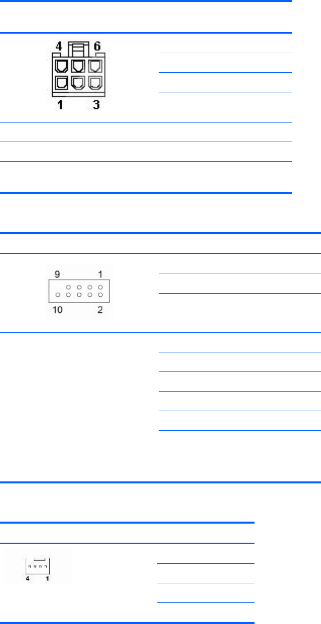
Auxiliary graphics card power
cable, P6
Pin Color Signal
1BLK/YELV12–G
2BLK/YELV12–G
3BLK/YELV12–G
4BLK GND
5BLK GND
6BLK GND
NOTE: The 6-pin power (auxiliary PCIe cable with black connector) can
provide up to 75 watts to PCIe graphics cards.
Internal USB 1 and USB 2, 2x5 Pin Signal (USB1) Signal (USB2)
1 +5V +5V
2 +5V +5V
3USB6# USB7#
4USB9# USB8#
CAUTION: Possible equipment damage.
The 2x5 connector can be mated to either
a wide 2x5 option cable connector or a
narrow 1x5 option cable connector.
To prevent damage to the connectors,
always connect a narrow 1x5 option cable
connector to pins 1,3,5, and 7 only of the
2x5 connector (pin 9 is not keyed on the
connector).
NOTE: USB 1 is DASH compatible using
pins 1, 3, 5, 7, and 10 (SMI).
5 USB6 USB7
6 USB9 USB8
7GND GND
8GND GND
9 (not keyed) (not keyed)
10 DETECT DETECT
Rear system fan Pin Signal
1GND
2 +12V
3Tach
4PWM
ENWW 159