
Specifications


Table Of Contents
- Product overview
- Setting up the operating system
- Restoring the operating system
- System management
- BIOS ROM
- The Computer Setup (F10) Utility
- Desktop management
- Initial computer configuration and deployment
- Installing a remote system
- Replicating the setup
- Updating and managing software
- HP Client Manager Software
- Altiris Client Management Solutions
- HP SoftPaq Download Manager
- System Software Manager
- ROM Flash
- FailSafe Boot Block ROM
- Workstation security
- Asset tracking
- SATA hard disk drive security
- Password security
- Establishing a setup password using Computer Setup (F10) Utility
- Establishing a power-on password using computer setup
- Entering a power-on password
- Entering a setup password
- Changing a power-on or setup password
- Deleting a power-on or setup password
- National keyboard delimiter characters
- Clearing passwords
- Chassis security
- Fault notification and recovery
- Dual-state power button
- Replacing components
- Warnings and cautions
- Service considerations
- Customer Self-Repair
- Removing and installing components
- Component locations
- Predisassembly procedures
- Disassembly order
- Removing the cable lock (optional)
- Side access panel
- Side access panel sensor (optional)
- Side access panel solenoid lock
- Bezel
- Front panel I/O device assembly
- Optical disk drive (mini-tower configuration)
- Optical disk drive (desktop configuration)
- Speaker
- Power supply
- Power connections
- Rear system fan assembly
- Memory
- Expansion card slot identification
- Expansion card
- Battery
- Hard disk drive
- CPU heatsink
- CPU
- System board
- Converting to desktop configuration
- Product recycling
- Diagnostics and troubleshooting
- Calling technical support
- Locating ID labels
- Locating warranty information
- Diagnosis guidelines
- Troubleshooting checklist
- HP troubleshooting resources and tools
- Troubleshooting scenarios and solutions
- Self-troubleshooting with HP Vision Diagnostics
- Diagnostic codes and errors
- Configuring RAID devices
- Configuring password security and resetting CMOS
- Connector pins
- System board designators
- Routine Care
- Locating HP resources
- Index
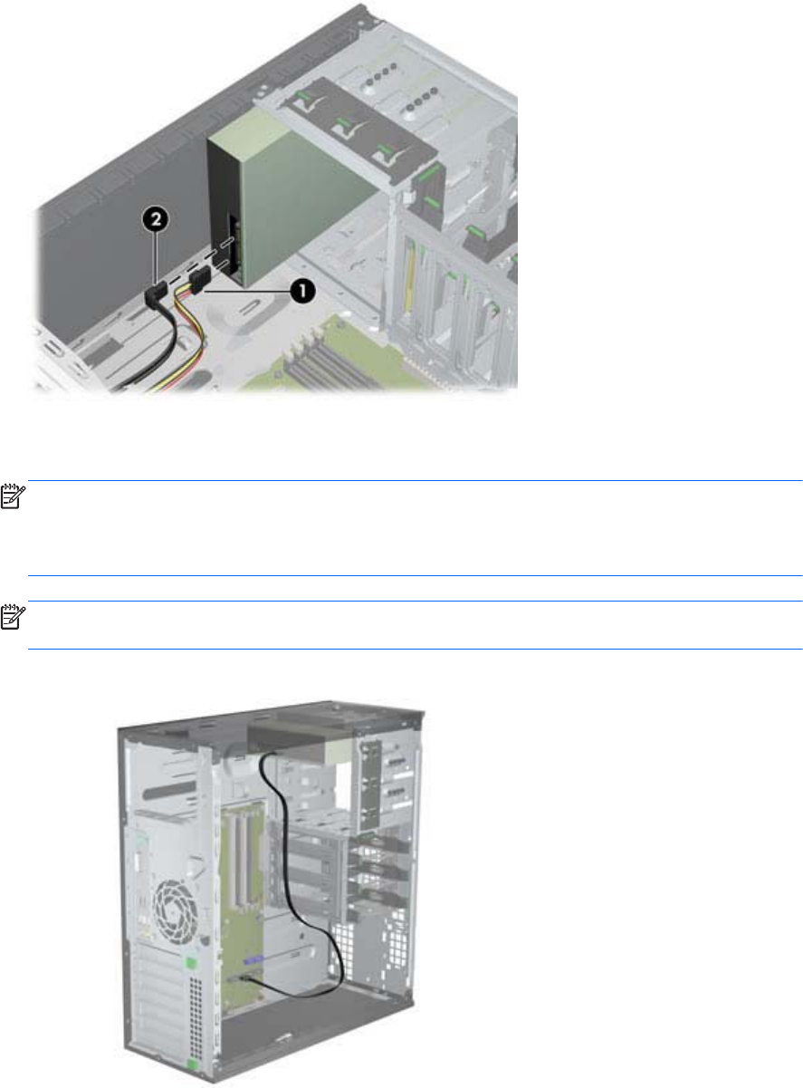
7. Connect the power cable (1) and data cables (2) to the drive as shown in the following figure.
Figure 5-13 Connecting power and data cables
8. Connect the optical disk drive data cable to the appropriate SATA port on the system board as
shown in the following figures.
NOTE: HP recommends using SATA ports 3 and 4 for optical disk drives, SATA ports 0 and 1
for primary hard disk drives, and port 5 only after all other ports have been used. (Refer to the
service label on the side access panel of your workstation to determine the location of the SATA
ports. These ports are also shown in Figure 5–1.)
NOTE: Blue SATA ports (SATA0 and SATA1) support SATA Gen3 (6 Gbit). Only SATA5 is
eSATA compatible.
Figure 5-14 Connecting power and data cables
74 Chapter 5 Replacing components ENWW