HP ProBook 4520s Notebook PC HP ProBook 4720s Notebook PC Maintenance and Service Guide
Bluetooth is a trademark owned by its proprietor and used by Hewlett-Packard Company under license. Intel, Core, and Celeron are trademarks of Intel Corporation in the United States and other countries. Microsoft, Windows, and Windows Vista are U.S. registered trademarks of Microsoft Corporation. SD Logo is a trademark of its proprietor. The information contained herein is subject to change without notice.
Safety warning notice WARNING! To reduce the possibility of heat-related injuries or of overheating the computer, do not place the computer directly on your lap or obstruct the computer air vents. Use the computer only on a hard, flat surface. Do not allow another hard surface, such as an adjoining optional printer, or a soft surface, such as pillows or rugs or clothing, to block airflow.
iv Safety warning notice
Table of contents 1 Product description ........................................................................................................... 1 2 External component identification ..................................................................................... 9 Top Components ...................................................................................................................... 9 TouchPad ............................................................................................
Grounding guidelines .............................................................................................. 45 Electrostatic discharge damage .................................................................. 45 Packaging and transporting guidelines ........................................ 46 Workstation guidelines .............................................................. 46 Equipment guidelines .................................................................
6 Specifications ................................................................................................................ 121 Computer specifications ........................................................................................................ 17.3-in display specifications ................................................................................................ 15.6-in display specifications ..........................................................................................
10 Recycling .................................................................................................................... 146 Battery ................................................................................................................................ 146 Display ............................................................................................................................... 146 Index ...........................................................................................
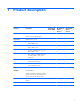
1 Product description Category Description HP ProBook 4520s UMA HP ProBook 4520s discrete Product Name HP ProBook 4520s Notebook PC • • HP ProBook 4720s Notebook PC Processors HP ProBook 4720s discrete • Intel® Core™ processors ● i7-620M, 2.26-GHz (Turbo up to 3.33 GHz), 4MB L3 cache • • • ● i5-540M, 2.53-GHz (Turbo up to 3.06 GHz), 3MB L3 cache • • • ● i5-520M, 2.4-GHz (Turbo up to 2.93 GHz), 3MB L3 cache • • • ● Core i5-430M, 2.26-GHz (Turbo up to 2.
Category Description HP ProBook 4520s UMA HP ProBook 4520s discrete 15.6-in HD LED backlight panel: • • ● 1366×768 AntiGlare ● 1366×768 AntiGlare for webcam ● 1366×768 AntiGlare for webcam and WWAN ● 1366×768 BrightView ● 1366×768 BrightView for webcam ● 1366×768 BrightView for webcam and WWAN 17.
Category Description HP ProBook 4520s UMA HP ProBook 4520s discrete HP ProBook 4720s discrete Hard drives Supports 9.5-mm, 6.35-cm (2.50-in) hard drives • • • Customer-accessible • • • Serial ATA • • • Supports the following drives: • • • HP 3D DriveGuard (not available on Linux) • • • Fixed, no modular requirements • • • SATA 12.
Category Description HP ProBook 4520s UMA HP ProBook 4520s discrete HP ProBook 4720s discrete 2 WLAN antennas built into display assembly • • • Supports option for no-WLAN • • • Support for the following WLAN formats: • • • ● Broadcom 802.11b/g ● Atheros 802.11 b/g/n (1 x 1) ● Realtek 802.11 b/g/n (1 x 2) ● Intel 802.11 b/g 1S/2R Russia only ● Intel 802.11 b/g/n 1S/2R ● Intel 802.11 a/b/g 1S/2R ● Intel 802.
Category Keyboard/ pointing devices Description HP ProBook 4520s UMA HP ProBook 4520s discrete HP ProBook 4720s discrete VGA (Dsub 15-pin) supporting 1600 × 1200 external resolution at 75-GHz (hot plug/ unplug with auto-detect) • • • Multi-pin AC power • • • HDMI • • • 15.6-in keyboard with integrated number pad and Clickpad • • 17.
Category Description HP ProBook 4520s UMA HP ProBook 4520s discrete HP ProBook 4720s discrete Windows Vista Home Basic 32 with Office 2007 Ready (Japan only) • • • Windows Vista Home Basic 32 with Office 2007 Personal (Japan only) • • • Windows Vista Home Basic 32 with Office 2007 Professional (Japan only) • • • Windows Vista Business 32 with Office 2007 Personal (Japan only) • • • Windows Vista Business 32 with Office Personal with PowerPoint (Japan only) • • • Windows Vista Busine
Category Description HP ProBook 4520s UMA HP ProBook 4520s discrete HP ProBook 4720s discrete Windows Vista Business 32 with MS Basics (Japan only) • • • Windows 7 32 (with XP Professional images) with MS Basics (Japan only) • • • FreeDOS • • • RedFlag Linux (People's Republic of China only) • • • SuSE Linux • • • Windows 7 Home Basic 32 • • • Windows 7 Home Premium 32 • • • Windows Vista Business 64 • • • Windows 7 Professional 32 • • • Windows 7 Professional 64 •
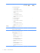
Category 8 Description HP ProBook 4520s UMA HP ProBook 4520s discrete HP ProBook 4720s discrete Hard drive • • • Memory module • • • Optical drive • • • WLAN module • • • WWAN module • • Chapter 1 Product description
2 External component identification NOTE: Depending on the operating system installed on your comouter, some components may function differently than described. Some functionality may not be supported by the operating system installed on your computer. Top Components TouchPad Component Description (1) To turn the TouchPad zone on and off, quickly double-tap the TouchPad off indicator. TouchPad off indicator light NOTE: When the TouchPad zone is active, the light is off.
Component Description (4) Functions like the right button on an external mouse. Right TouchPad button *This table describes factory settings.
Lights NOTE: Your computer may look slightly different from the illustration in this section. Component Description (1) ● Amber: The TouchPad is off. ● Off: The TouchPad is on. TouchPad off indicator (2) Caps lock light On: Caps lock is on. (3) HP QuickLook light Blinking: QuickLook is being opened or closed. (4) HP QuickWeb light Blinking: QuickWeb browser is being opened or closed. (5) Power light ● On: The computer is on. ● Blinking: The computer is in the Sleep state.
Buttons, switches, and speakers (select models only) NOTE: Your computer may look slightly different from the illustration in this section. Component Description (1) Speakers (2) Produce sound. (2) Internal display switch Turns off the display if the display is closed while the power is on. (3) Power button ● When the computer is off, press the button to turn on the computer. ● When the computer is on, press the button to shut down the computer.
Keys Component Description (1) esc key Displays system information when pressed in combination with the fn key. (2) fn key Executes frequently used system functions when pressed in combination with a function key, the num lk key, or the esc key. (3) Windows logo key Displays the Windows Start menu. (4) Windows applications key Displays a shortcut menu for items beneath the pointer. (5) Integrated numeric keypad keys Can be used like the keys on an external numeric keypad.
Front components Component Description (1) ● Blinking white: The hard drive or optical drive is being accessed. ● Amber: HP 3D DriveGuard has temporarily parked the hard drive.
Component Description (1) USB ports (2) Connect optional USB devices. (2) RJ-11 (modem) jack (select models only) Connects a modem cable. (3) Optical drive (select models only) Reads optical discs and, on select models, also writes to optical discs. (4) Optical drive light (select models only) Blinking: The optical drive is being accessed. (5) AC adapter light ● On: The computer is connected to external power and the battery is charging.
Left-side components Component Description (1) Attaches an optional security cable to the computer. Security cable slot NOTE: The security cable is designed to act as a deterrent, but it may not prevent the computer from being mishandled or stolen. (2) Vent Enables airflow to cool internal components. NOTE: The computer fan starts up automatically to cool internal components and prevent overheating. It is normal for the internal fan to cycle on and off during routine operation.
Bottom components Component Description (1) Battery release latches (2) Release the battery from the battery bay. (2) Battery bay Holds the battery. (3) SIM slot (select models only) Contains a wireless subscriber identity module (SIM). The SIM slot is located inside the battery bay. Display NOTE: Your computer may look slightly different from the illustration in this section.
18 Component Description (1) Internal display switch Turns off the display if the display is closed while the power is on. (2) Internal microphone Records sound. (3) Webcam light (select models only) On: The webcam is in use. (4) Webcam (select models only) Records audio and video and captures still photographs.
Wireless antennas The antennas send and receive signals from one or more wireless devices. These antennas are not visible from the outside of the computer. Component Description (1) WWAN antennas (2)* (select models only) Send and receive wireless signals to communicate with wireless wide-area networks (WWAN). (2) WLAN antennas (2)* Send and receive wireless signals to communicate with wireless local area networks (WLAN). *The antennas are not visible from the outside of the computer.
Additional hardware components Component Description (1) Power cord* Connects an AC adapter to an AC outlet. (2) Battery* Powers the computer when the computer is not plugged into external power. (3) AC adapter Converts AC power to DC power. *Batteries and power cords vary in appearance by country or region.
3 Illustrated parts catalog Service tag When ordering parts or requesting information, provide the computer serial number and model description provided on the service tag. (1) Product name: This is the product name affixed to the front of the computer. (2) Serial number (s/n): This is an alphanumeric identifier that is unique to each product. (3) Part number/product number (p/n): This number provides specific information about the product's hardware components.
Computer major components Item Description (1) Display assembly (includes microphone, 2 WLAN antenna transceivers and cables and, on select computer models, 2 WWAN antenna transceivers and cables) For use only with computers with 17.
Item Description ● 17.3-in HD BrightView display assembly for use in computers equipped with webcam and WWAN (1600×900 resolution) 598708-001 ● 17.3-in HD BrightView display assembly (1600×900 resolution) 606167-001 ● 17.3-in HD AntiGlare display assembly for use in computers equipped with webcam and WWAN (1600×900 resolution) 606166-001 ● 17.3-in HD AntiGlare display assembly (1600×900 resolution) 606165-001 For use only with computers with 15.6-in displays (2) (3) ● 15.
Item Description For use in computers with 17.3-in displays 598689-001 For use in computers with 15.6-in displays 598688-001 For use in computers with 15.6-in displays and red trim 604852-001 For use in computers with 17.3-in displays with fingerprint reader 599805-001 For use in computers with 15.6-in displays with fingerprint reader 599804-001 For use in computers with 15.
Item Description System board with UMA graphics subsystem memory for use only in the People's Republic of China and Russia 605168-001 System board with UMA graphics subsystem memory and WWAN for use only in the People's Republic of China and Russia 605170-001 (14) Power connector (part of Base Cable Kit 603188-001 for computers with 17.3-in displays and Base Cable Kit 599807-001 for computers with 15.6-in displays) (15) RJ-11 connector (part of Base Cable Kit 603188-001 for computers with 17.
Item Description ● (18) For use in Afghanistan, Albania, Algeria, Andorra, Angola, Antigua and Barbuda, Argentina, Armenia, Aruba, Australia, Austria, Azerbaijan, the Bahamas, Bahrain, Bangladesh, Barbados, Belarus, Belgium, Belize, Benin, Bermuda, Bhutan, Bolivia, Bosnia and Herzegovina, Botswana, Brazil, the British Virgin Islands, Brunei, Bulgaria, Burkina Faso, Burundi, Cameroon, Cape Verde, the Central African Republic, Chad, Chile, the People's Republic of China, Colombia, Comoros, the Congo, Costa
Item Description i5-540M, 2.53-GHz, 3-MB cache 594188-001 i7-620M, 2.26-GHz, 4-MB cache 587259-001 (19) RTC battery 449137-001 (20) HP un2420 Broadband Module 531993-001 (21) Optical drive extender for use only in computers with 17.3-in displays 598687-001 (22) Modem module NOTE: The modem module spare part kit does not include a modem module cable. The modem module cable is included in the Base Cable Kit , spare part numbers 599807-001.
Display assembly components 28 Item Description (1) Display bezel Spare part number For use in computers with 17.3-in displays without webcam 600924-001 For use in computers with 15.6-in displays without webcam 598690-001 For use in computers with 17.3-in displays with webcam 600927-001 For use in computers with 15.6-in displays with webcam 600926-001 (2) Webcam module 598671-001 (3) Display (For Reference only. Not spared separately.
Item Description (4) Display Hinge Kit Spare part number For use in computers with 17.3-in displays 602677-001 For use in computers with 15.6-in displays 598679-001 (5) Microphone cable (6) LCD Cable Kit with webcam cable For use in computers with 17.3-in displays 602999-001 For use in computers with 15.6-in displays 600925-001 (7) WLAN and WWAN antenna transceivers and cables (8) Display enclosure For use in computers with 17.3-in displays 600929-001 For use in computers with 15.
Cable Kits Item Description Spare part number Base Cable Kit 30 for use in computers with 17.3-in displays, includes DC-in cable (1), USB cable (2), Bluetooth cable (3), and RJ-11 cable (4). 603188-001 for use in computers with 15.6-in displays, includes DC-in cable (1), USB cable (2), Bluetooth cable (3), and RJ-11 cable (4). 599807-001 (1) DC-in cable, lengths differ for 17.3-in and 15.6-in computers (2) USB cable, lengths differ for 17.3-in and 15.
Item Description Spare part number Misc LCD Cable Kit for use in computers with 15.6-in displays, includes microphone cable (1), WWAN transceiver with cable (2), and WLAN transceiver with cable (3) 599806-001 for use in computers with 17.3-in displays, includes items (1), (2), and (3) 606974-001 (1) Microphone cable, lengths differ for 17.3-in and 15.6-in computers (2) WWAN transceiver with cable, lengths differ for 17.3-in and 15.
Item Description Spare part number for use in computers with 17.3-in displays 602999-001 for use in computers with 15.6-in displays 600925-001 LCD Cable without webcam cable for use in computers with 17.3-in displays 606973-001 for use in computers with 15.
Miscellaneous parts Description Spare part number AC adapters 65-W AC adapter for use in computers with UMA graphics 463958-001 90-W Slimline PFC AC adapter for use in computers with discrete graphics 463955-001 Power cords For use in Argentina 490371-D01 For use in Australia and New Zealand 490371-011 For use in Brazil 490371-201 For use in Denmark 490371-081 For use in Europe, the Middle East, and Africa 490371-021 For use in India 490371-D61 For use in Israel 490371-BB1 For use in Ita
Description Spare part number Screw Kit, includes: 598672-001 ● (5) Phillips 2.0×2.0 screws ● (5) Phillips 2.0×2.5 broadhead screws ● (5) Phillips 2.0×2.5 screws ● (5) Phillips 2×7.0 screws ● (5) Phillips 2.5×3.0 screws ● (5) Phillips 2.5×5.0 screws ● (5) Torx 2.5×5.0 screws ● (5) Torx 2.5×6.0 screws ● (5) Phillips 2.5×8.0 screws ● (10) Phillips 3.0×4.
Sequential part number listing Spare part number Description 449137-001 RTC battery 463955-001 90-W Slimline PFC AC adapter for use in computers with discrete graphics 463958-001 65-W AC adapter for use in computers with UMA graphics 490371-001 Power cord for use in the United States 490371-011 Power cord for use in Australia and New Zealand 490371-021 Power cord for use in Europe, the Middle East, and Africa 490371-031 Power cord for use in the United Kingdom 490371-061 Power cord for use
36 Spare part number Description 504593-004 Broadcom 4312 802.
Spare part number Description 572520-001 Intel Wi-Fi Link 1000, 802.
38 Spare part number Description 598674-001 Switch cover with power button switch for use in computers with 15.6-in displays 598675-001 Switch cover with power button switch for use in computers with 17.3-in displays 598677-001 Fan/heat sink assembly for computers with discrete graphics 598678-001 Rubber Kit, includes: 4 rubber feet, 2 back edge screw covers and 4 mylar screw covers for LCD bezel. 598679-001 Display Hinge Kit for use in computers with 15.
Spare part number Description 598691-231 Keyboard for use in Slovakia on computers with 15.6-in displays 598691-251 Keyboard for use in Russiaon computers with 15.6-in displays 598691-261 Keyboard for use in Bulgaria on computers with 15.6-in displays 598691-281 Keyboard for use in Thailand on computers with 15.6-in displays 598691-291 Keyboard for use in Japan on computers with 15.6-in displays 598691-A41 Keyboard for use in Europe on computers with 15.
40 Spare part number Description 598692-221 Keyboard for use in the Czech Republic on computers with 17.3-in displays 598692-231 Keyboard for use in Slovakia on computers with 17.3-in displays 598692-251 Keyboard for use in Russia on computers with 17.3-in displays 598692-261 Keyboard for use in Bulgaria on computers with 17.3-in displays 598692-281 Keyboard for use in Thailand on computers with 17.3-in displays 598692-291 Keyboard for use in Japan on computers with 17.
Spare part number Description 598867-001 System board with UMA graphics subsystem memory 598868-001 System board with discrete graphics subsystem memory 598869-001 System board with UMA graphics subsystem memory and WWAN 599804-001 Palm rest for use in computers with 15.6-in displays with TouchPad, fingerprint reader, and cables 599805-001 Palm rest for use in computers with 17.
42 Spare part number Description 605168-001 System board with UMA graphics subsystem memory for use only in the People's Republic of China and Russia 605169-001 System board with discrete graphics subsystem memory for use only in the People's Republic of China and Russia 605170-001 System board with UMA graphics subsystem memory and WWAN for use only in the People's Republic of China and Russia 605660-005 Atheros 9285G 802.11b/g/n WiFi Adapter 606165-001 17.
4 Removal and replacement procedures Preliminary replacement requirements Tools required You will need the following tools to complete the removal and replacement procedures: ● Flat-bladed screwdriver ● Magnetic screwdriver ● Phillips P0 and P1 screwdrivers ● Torx T8 screwdriver Service considerations The following sections include some of the considerations that you must keep in mind during disassembly and assembly procedures.
Cables and connectors CAUTION: When servicing the computer, be sure that cables are placed in their proper locations during the reassembly process. Improper cable placement can damage the computer. Cables must be handled with extreme care to avoid damage. Apply only the tension required to unseat or seat the cables during removal and insertion. Handle cables by the connector whenever possible. In all cases, avoid bending, twisting, or tearing cables.
Grounding guidelines Electrostatic discharge damage Electronic components are sensitive to electrostatic discharge (ESD). Circuitry design and structure determine the degree of sensitivity. Networks built into many integrated circuits provide some protection, but in many cases, ESD contains enough power to alter device parameters or melt silicon junctions. A discharge of static electricity from a finger or other conductor can destroy static-sensitive devices or microcircuitry.
Packaging and transporting guidelines Follow these grounding guidelines when packaging and transporting equipment: ● To avoid hand contact, transport products in static-safe tubes, bags, or boxes. ● Protect ESD-sensitive parts and assemblies with conductive or approved containers or packaging. ● Keep ESD-sensitive parts in their containers until the parts arrive at static-free workstations. ● Place items on a grounded surface before removing items from their containers.
Equipment guidelines Grounding equipment must include either a wrist strap or a foot strap at a grounded workstation. ● When seated, wear a wrist strap connected to a grounded system. Wrist straps are flexible straps with a minimum of one megohm ±10% resistance in the ground cords. To provide proper ground, wear a strap snugly against the skin at all times. On grounded mats with banana-plug connectors, use alligator clips to connect a wrist strap.
Component replacement procedures This section provides removal and replacement procedures. There are many screws, in many different sizes, that must be removed, replaced, or loosened when servicing the computer. Make special note of each screw size and location during removal and replacement.
Computer feet The computer feet are adhesive-backed rubber pads. The feet are included in the Rubber Kit, spare part number 598678-001. There are 4 rubber feet that attach to the base enclosure in the locations illustrated below.
Battery Description Spare part number 8-cell, 73-Wh, 2.55-Ah Li-on battery for use in computers with 17.3-in displays 593576-001 6-cell, 47-Wh, 2.2-Ah Li-on battery for use in computers with 15.6-in displays 593572-001 6-cell, 93-Wh, 2.8-Ah Li-on battery for use in computers with 15.6-in displays 593573-001 Before disassembling the computer, follow these steps: 1. Shut down the computer.
Switch cover and keyboard Description Spare part number Switch cover with power button board For use in computers with 17.3-in displays 598675-001 For use in computers with 15.6-in displays 598674-001 Keyboards for use in computers with 17.3-in displays 598692-xx1 Keyboards for use in computers with 15.6-in displays 598691-xx1 NOTE: For a detailed list of available keyboards, see Sequential part number listing on page 35. Before removing the switch cover and keyboard, follow these steps: 1.
2. To remove the switch cover, remove the following: (1) Two screw covers on the rear edge of the computer (2) Two PM2.5×2.5 screws (3) Three PM2.0×2.5 broadhead screws located in the battery bay 52 3. Open the computer as far as possible. 4. Slide the switch cover back (1), and then remove it from the computer (2).
5. Remove the two Phillips PM2.5×5.0screws that secure the keyboard to the computer. 6. Slide the keyboard back toward the display (1), and then rotate it forward (2) until it rests upsidedown (3) the palm rest.
7. Release the zero insertion force (ZIF) connector (1) to which the keyboard cable is attached, and disconnect the keyboard cable (2) from the system board. NOTE: Only disconnect the keyboard cable from the system board when replacing the keyboard or removing the top cover. It is not recommended that you disconnect the cable unless it is absolutely necessary. 8. Remove the keyboard. Reverse this procedure to install the switch cover and keyboard.
Memory module NOTE: When adding a second memory module, be sure it is the same type and speed as the installed memory module. Description Spare part number 2-GB (PC3-10600, 1333-MHz, DDR3) 598701-001 1-GB (PC3-10600, 1333-MHz, DDR3 598700-001 Before removing the memory module, follow these steps: 1. Shut down the computer. If you are unsure whether the computer is off or in Hibernation, turn the computer on, and then shut it down through the operating system. 2.
3. Remove the memory module (2) by pulling the module away from the slot at an angle. NOTE: Memory modules are designed with a notch to prevent incorrect insertion into the memory module slot. Reverse this procedure to install a memory module. Optical drive NOTE: All optical drive spare part kits include an optical drive bezel.
4. Remove the battery (see Battery on page 50). 5. Remove the switch cover and keyboard (see Switch cover and keyboard on page 51). NOTE: It is not necessary to disconnect the keyboard cable from the system board to remove the optical drive. Remove the optical drive: 1. Position the computer with the right side toward you. 2. Remove the Phillips PM2.5×5.0 screw (1) that secures the optical drive to the computer. 3.
7. Remove the optical drive bracket (2). Reverse this procedure to reassemble and install an optical drive. Power button board Description Spare part number Switch cover with power button board For use in computers with 17.3-in displays 598675-001 For use in computers with 15.6-in displays 598674-001 Before removing the power button board, follow these steps: 58 1. Shut down the computer.
Remove the power button board. 1. Release the ZIF connector (1) and disconnect the ribbon cable (2) from the system board. 2. Remove the screw (1) that secures the power button board to the base pan and the slide the board out of the retainer (2) to the left (3) to remove it. Reverse this procedure to install the power button board.
Speakers Description Spare part number For use in computers with 17.3-in displays 598686-001 For use in computers with 15.6-in displays 598685-001 Before removing the speakers, follow these steps: 1. Shut down the computer. If you are unsure whether the computer is off or in Hibernation, turn the computer on, and then shut it down through the operating system. 2. Disconnect all external devices connected to the computer. 3.
3. Remove the cables from the routing channels and lift the speakers (3) from the computer. Remove the speakers from the 15.6-in computer: 1. Remove the two PM2.5x6.0 screws (1) that secure the speakers to the top cover. 2. Disconnect the speaker cable connector (2) from the system board.
3. Remove the cables from the routing channels and the speakers (3) from the computer. Reverse this procedure to install the speakers. Thermal shield NOTE: The spare part number for the thermal shield is 603700-001. Before removing the thermal shield, follow these steps: 1. Shut down the computer. If you are unsure whether the computer is off or in Hibernation, turn the computer on, and then shut it down through the operating system. 2. Disconnect all external devices connected to the computer. 3.
Remove the thermal shield on the 17.3-in computer: 1. Position the computer right-side up with the front toward you. 2. Remove the PM2.5×3.0 screw (1) from the thermal shield. 3. Raise the thermal shield (2) and remove it (3) from the computer. Remove the thermal shield on the 15.6-in computer: 1. Position the computer right-side up with the front toward you. 2. Remove the two PM2.5×3.0 screws (1) and (2) from the thermal shield. 3.
Reverse this procedure to reassemble and install an optical drive.
WLAN module Description Spare part number Intel Centrino Advanced-N6200 802.
Description Spare part number ● 504593-004 For use in Afghanistan, Albania, Algeria, Andorra, Angola, Antigua and Barbuda, Argentina, Armenia, Aruba, Australia, Austria, Azerbaijan, the Bahamas, Bahrain, Bangladesh, Barbados, Belarus, Belgium, Belize, Benin, Bermuda, Bhutan, Bolivia, Bosnia and Herzegovina, Botswana, Brazil, the British Virgin Islands, Brunei, Bulgaria, Burkina Faso, Burundi, Cameroon, Cape Verde, the Central African Republic, Chad, Chile, the People's Republic of China, Colombia, Comor
Before removing the WLAN module, follow these steps: 1. Shut down the computer. If you are unsure whether the computer is off or in Hibernation, turn the computer on, and then shut it down through the operating system. 2. Disconnect all external devices connected to the computer. 3. Disconnect the power from the computer by first unplugging the power cord from the AC outlet and then unplugging the AC adapter from the computer. 4. Remove the battery (see Battery on page 50). 5.
4. Remove the WLAN module (3) by pulling the module away from the slot at an angle. NOTE: WLAN modules are designed with a notch (4) to prevent incorrect insertion. Reverse this procedure to install the WLAN module. WWAN module NOTE: Only computers with UMA graphics include a WWAN module. NOTE: The spare part number for the HP un2420 Broadband Module is 531993-001.
4. Remove the battery (see Battery on page 50). 5. Remove the switch cover and keyboard (see Switch cover and keyboard on page 51) Remove the WWAN module: 1. Position the computer right-side up with the front toward you. 2. Disconnect the WWAN antenna cables (1) from the terminals on the WWAN module. NOTE: The red WWAN antenna cable is connected to the WWAN module “Main” terminal. The blue WWAN antenna cable is connected to the WWAN module “Aux” terminal.
Description Spare part number Heat sink for use in computers with UMA graphics subsystems 598676-001 Heat sink for use in computers with discrete graphics subsystems 598677-001 Before removing the heat sink, follow these steps: 1. Shut down the computer. If you are unsure whether the computer is off or in Hibernation, turn the computer on, and then shut it down through the operating system. 2. Disconnect all external devices connected to the computer. 3.
3. Disconnect the fan cable from the system board (7), and then remove the heat sink (8).
72 4. Clean the thermal material from the surfaces of the heat sink components (1) and (3) and from the system board (2) and (4) when the heat sink is removed. Replacement thermal material is included with all heat sink, system board, and processor spare part kits. ● For computers with UMA subsystem memory on the system board, follow these steps: 1. Position the computer right-side up with the front toward you. 2.
3. Disconnect the fan cable from the system board (5), and remove the heat sink (6).
4. Clean the thermal material from the surfaces of the heat sink components (1) and the system board (2) each time the heat sink is removed. Replacement thermal material is included with all heat sink, system board, and processor spare part kits. Reverse this procedure to install the heat sink and fan. Processor NOTE: The processor spare part kit includes replacement thermal material. 74 Description Spare part number i3-330M, 2.13-GHz 597622-001 i3-350M, 2.26-GHz 597623-001 i5-430M, 2.
Before removing the processor, follow these steps: 1. Shut down the computer. If you are unsure whether the computer is off or in Hibernation, turn the computer on, and then shut it down through the operating system. 2. Disconnect all external devices connected to the computer. 3. Disconnect the power from the computer by first unplugging the power cord from the AC outlet and then unplugging the AC adapter from the computer. 4. Remove the battery (see Battery on page 50). 5.
Reverse this procedure to install the processor. Palm rest Description Spare part number Palm rest for 17.3-in displays (includes TouchPad) 598689-001 Palm rest for 17.3-in displays with fingerprint reader (includes TouchPad) 599805-001 Palm rest for 15.6-in displays (includes TouchPad) 598688-001 Palm rest for 15.6-in displays with red trim (includes TouchPad) 604852-001 Palm rest for 15.6-in displays with fingerprint reader (includes TouchPad) 599804-001 Palm rest for 15.
4. Release the ZIF connectors (1) and (3) to which the TouchPad and fingerprint cables are connected, and then disconnect the cables (2) and (4) from the system board. NOTE: Only select models are equipped with fingerprint readers. 5. Remove the palm rest. Reverse this procedure to install the palm rest.
Hard drive NOTE: The hard drive spare part kit includes a hard drive bracket. Description Spare part number 500-GB, 7200-rpm hard drive 598698-001 320-GB, 7200-rpm hard drive 598697-001 250-GB, 7200-rpm hard drive 598696-001 Before removing the hard drive, follow these steps: 1. Shut down the computer. If you are unsure whether the computer is off or in Hibernation, turn the computer on, and then shut it down through the operating system. 2.
4. Remove the hard drive (4) from the hard drive bay. 5. If it is necessary to replace the hard drive bracket, remove the two Phillips PM3.0×4.0 hard drive bracket screws (1) from each side of the hard drive. 6. Lift the bracket (2) straight up to remove it from the hard drive. Reverse this procedure to reassemble and install the hard drive.
Display assembly on computers with 17.3-in displays NOTE: The Miscellaneous LCD Cable Kit, spare part number 599806-001, includes 2 WLAN antenna transceivers and cables. Description Spare part number For use only with computers with 17.3-in displays ● 17.3-in HD BrightView display assembly for use in computers equipped with webcam and WWAN (1600×900 resolution) 598708-001 ● 17.3-in HD BrightView display assembly (1600×900 resolution) 606167-001 ● 17.
5. Disconnect and remove the WLAN wireless antenna cables (4) from the tape, clips, and routing channels built into the top cover. Remove the display assembly: CAUTION: Support the display assembly when removing the following screws. Failure to support the display assembly can result in damage to the display assembly and other computer components. 1. Remove the six Torx M2.5×6.0 screws (1) that secure the display assembly to the computer.
82 2. Lift the display assembly (2) straight up. 3. If it is necessary to replace the display bezel, display enclosure, or display hinges, remove the two mylar screw covers (1) at the bottom corners of the display and the two Torx M2.0×6.0 screws (2) that secure the display bezel to the display assembly. 4. Flex the bottom bezel (1) around the hinge areas on the inside of the display enclosure and work around the periphery of the bezel (2) and (3).
5. When the bezel is free, lift it (4) from the display. 6. If it is necessary to replace the webcam module, gently pull the webcam module away from the double-sided tape on the display enclosure (1) and disconnect the webcam cable from the module (2).The webcam module with cable can be ordered by using spare part number 598671-001.
84 7. If it is necessary to replace the display hinges, remove the display panel by removing the two Torx M2.0×6.0 screws (1) that secure the panel to the top of the display enclosure, and then remove the four Torx M2.0×6.0 screws (2) located at the hinge arms. This will allow the panel to be lifted from the enclosure. 8. Remove the eight Phillips PM2.0×3.0 screws (1) that secure the display hinges to the display panel, and then remove the display hinges (2).
10. Disconnect the display cable from the back of the display panel (3) and remove the webcam cable (4) from the raceway. The display cable is spared in the LCD cable kit, spare part number 599806-001. Reverse this procedure to reassemble and install the display assembly.
Display assembly on computers with 15.6-in displays NOTE: For information about removing the display from 17.3-in models, see Display assembly on computers with 17.3-in displays on page 80. NOTE: The Miscellaneous LCD Cable Kit, spare part number 599806-001, includes 2 WLAN antenna transceivers and cables. Description Spare part number For use only with computers with 15.6-in displays ● 15.
6. Disconnect the power button cable from the system board (see Power button board on page 58). 7. Remove the speakers (see Speakers on page 60) 8. Remove the thermal shield (see Thermal shield on page 62). Remove the display cables: 1. Remove the tape that holds the cables in place(1). Disconnect the display and webcam cables from the system board and from the routing channels. 2. Disconnect the cable connectors for the display (2) and microphone (3) from the system board. 3.
88 4. Lift the display assembly up and off the computer (2). 5. If it is necessary to replace the display bezel, display enclosure, or display hinges, remove the two mylar screw covers (1) and the 2 Torx M2.5×6.0 screws (2) that secure the display bezel to the display assembly. The screw covers are available in the Rubber Kit, spare part number 598678-001. 6. Flex the bottom bezel (1)around the hinge areas on the inside of the display enclosure and work around the periphery of the bezel (2) and (3).
7. Lift the bezel (4) until it disengages completely. 8. If it is necessary to replace the webcam module, gently pull the webcam module away from the double-sided tape on the display enclosure (1) and disconnect the webcam cable from the module (2). The webcam module and cable can be ordered by using spare part number 598671-001. NOTE: To replace the webcam module in the display enclosure, align the holes on the webcam module with the pins on the display enclosure and press onto the double-sided tape.
10. Remove the display panel from the housing (3). 11. Remove the six Phillips PM2.0×3.0 screws (1) that secure the display hinges to the display panel, and then remove the display hinges (2). The left and right display hinges are available in the Hinge Kit, spare part number 598679-001 for computers with 15.6-in displays. To replace the webcam, webcam cable, and display cable: 1. 90 Remove the microphone from its socket (1) and lift its cable (2) from the raceway.
2. Remove the webcam cable (3)from the raceway and then, remove the cable assembly (4). NOTE: The cables are attached to the display panel with adhesive tape. To remove the WLAN and WWAN antennas: 1. Peel the WLAN (1) and WWAN (2) antenna receivers from the housing. 2. Route the antenna cables (3) out of the routing channels in the inside of the display housing. Reverse this procedure to install the display assembly.
Top cover NOTE: The top cover removal procedures differ for 17.3-in and 15.6-in computers. Description Spare part number Top cover for use in computers with 17.3-in displays 598683-001 Top cover for use in computers with 15.6-in displays 598682-001 Before removing the top cover, follow these steps: 1. Shut down the computer. If you are unsure whether the computer is off or in Hibernation, turn the computer on, and then shut it down through the operating system. 2.
2. Disconnect the power button board cable from the system board by releasing the ZIF connector (1), and then disconnecting the cable (2). 3. Remove the 17 Torx M2.5×6.0 screws that secure the top cover to the computer.
4. Remove the ExpressCard bezel (1), then angle the top cover up (2), and lift it up (3) until it disengages from the base enclosure. Remove the top cover on 15.6-in computers: 94 1. Position the computer right-side up with the front toward you. 2. Disconnect the power button board cable from the system board by releasing the ZIF connector (1), and then disconnecting the cable (2).
3. Remove the 10 Torx M2.5×6.0 screws that secure the top cover to the computer. 4. Remove the ExpressCard bezel (1), then angle the top cover up (2), and lift it up (3) until it disengages from the base enclosure. Reverse this procedure to install the top cover.
RTC battery Description Spare part number RTC battery 449137-001 Before removing the RTC battery, follow these steps: 1. Shut down the computer. If you are unsure whether the computer is off or in Hibernation, turn the computer on, and then shut it down through the operating system. 2. Disconnect all external devices connected to the computer. 3. Disconnect the power from the computer by first unplugging the power cord from the AC outlet and then unplugging the AC adapter from the computer. 4.
2. Release the RTC battery from the socket (1) on the system board and lift the battery (2) up. Reverse this procedure to install the RTC battery.
Bluetooth module NOTE: The Bluetooth module spare part kit does not include a Bluetooth module cable. The Bluetooth module cable is included in the Cable Kit, spare part number 599807-001. See Cable Kits on page 30 for more Cable Kit spare part number information. Description Spare part number HP Integrated Bluetooth 2.1 module for use in all countries and regions except Japan and Asia Pacific countries and regions 537921-001 Before removing the Bluetooth module, follow these steps: 1.
3. Remove the Bluetooth antenna (3) from the base enclosure. Reverse this procedure to install the Bluetooth module. Modem module Description Spare part number For use in all countries and regions except Australia and New Zealand 510100-001 For use only in Australia and New Zealand 510100-011 Before removing the modem module, follow these steps: 1. Shut down the computer.
7. Remove the power button board cable (see Power button board on page 58). 8. Remove the speakers (see Speakers on page 60). 9. Remove the thermal shield (see Thermal shield on page 62). 10. Remove the display assembly (see Display assembly on computers with 17.3-in displays on page 80 or Display assembly on computers with 15.6-in displays on page 86). 11. Remove the palm rest (see Palm rest on page 76). 12. Remove the hard drive (see Hard drive on page 78). 13.
Audio board NOTE: The spare part number for the audio board is 598684-001. Before removing the audio board, follow these steps: 1. Shut down the computer. If you are unsure whether the computer is off or in Hibernation, turn the computer on, and then shut it down through the operating system. 2. Disconnect all external devices connected to the computer. 3. Disconnect the power from the computer by first unplugging the power cord from the AC outlet and then unplugging the AC adapter from the computer.
4. Remove the audio board (4) by pulling the module straight up and off the computer. Reverse this procedure to install the audio board.
System board NOTE: The system board spare part kit includes replacement thermal material.
When replacing the system board, be sure that the following components are removed from the defective system board and installed on the replacement system board: ● Memory module (see Memory module on page 55) ● WLAN module (see WLAN module on page 65) ● WWAN module (see WWAN module on page 68) ● Modem module (see Modem module on page 99) ● Processor (see Processor on page 74) ● Audio board (see Audio board on page 101) Remove the system board: 1.
6. Disconnect the power cable (1) from the system board and the connector (2) from the computer. 7. Disconnect the RJ11 cable (1) from the system board and the connector (2) from the computer.
8. Remove the screw (1) that secures the USB to the computer, disconnect the cable (2) from the system board and then, remove the device (3) from the computer. Reverse this procedure to install the system board. USB connector assembly NOTE: The USB connector assembly is included in the Cable Kit, spare part number 603188-001 for computers with 17.3-in displays and in 599807-001 for computers with 15.6-in displays. Before removing the USB connector assembly, follow these steps: 1. Shut down the computer.
9. Remove the thermal shield (see Thermal shield on page 62). 10. Remove the display assembly (see Display assembly on computers with 17.3-in displays on page 80 or Display assembly on computers with 15.6-in displays on page 86). 11. Remove the palm rest (see Palm rest on page 76). 12. Remove the hard drive (see Hard drive on page 78). 13. Remove the top cover (see Top cover on page 92). Remove the USB connector assembly: 1. Position the computer right-side up with the right side toward you. 2.
Before removing the RJ-11 connector assembly, follow these steps: 1. Shut down the computer. If you are unsure whether the computer is off or in Hibernation, turn the computer on, and then shut it down through the operating system. 2. Disconnect all external devices connected to the computer. 3. Disconnect the power from the computer by first unplugging the power cord from the AC outlet and then unplugging the AC adapter from the computer. 4. Remove the battery (see Battery on page 50). 5.
3. Lift the R-11 connector (2) from its holder and out of the base enclosure. Reverse this procedure to install the RJ-11 connector assembly. Power connector assembly NOTE: The power connector assembly is included in the Base Cable Kit, spare part number 603188-0001 for computers with 17.3-in displays and 599807-001 for computers with 15.6-in displays. Before removing the power connector assembly, follow these steps: 1. Shut down the computer.
e. Thermal shield (see Thermal shield on page 62) f. Display assembly (see Display assembly on computers with 17.3-in displays on page 80 or Display assembly on computers with 15.6-in displays on page 86) g. Palm rest (see Palm rest on page 76) h. Hard drive (see Hard drive on page 78) i. Top cover (see Top cover on page 92) Remove the power connector assembly: 1. Position the computer right-side up with the right side toward you. 2.
5 Computer Setup Computer Setup Starting Computer Setup Computer Setup is a preinstalled, ROM-based utility that can be used even when the operating system is not working or will not load. NOTE: Some of the Computer Setup menu items listed in this guide may not be supported by your computer or your operating system. NOTE: An external keyboard or mouse connected to a USB port can be used with Computer Setup only if USB legacy support is enabled. To start Computer Setup, follow these steps: 1.
NOTE: You can use either a pointing device (TouchPad, pointing stick, or USB mouse) or the keyboard to navigate and make selections in Computer Setup. 2. Press f10 to enter BIOS Setup. 3. Select the File, Security, or System Configuration menu. To exit Computer Setup menus, choose one of the following methods: ● To exit Computer Setup menus without saving your changes, click the Exit icon in the lower-left corner of the screen, and then follow the on-screen instructions.
Computer Setup menus The menu tables in this section provide an overview of Computer Setup options. NOTE: Some of the Computer Setup menu items listed in this chapter may not be supported by your computer or your operating system. File menu Select To do this System Information ● View identification information for the computer and the batteries in the system. ● View specification information for the processor, cache and memory size, system ROM, video revision, and keyboard controller version.
Select To do this Ignore Changes and Exit Cancel any changes entered during the current session. Then exit and restart the computer. Save Changes and Exit Save any changes entered during the current session. Then exit and restart the computer. Your changes go into effect when the computer restarts.
Security menu NOTE: Some of the menu items listed in this section may not be supported by your computer or your operating system. Select To do this Setup BIOS Administrator Password Set up a BIOS administrator password. User Management > Create a New BIOS User Account (requires a BIOS administrator password) ● Select from a list of BIOS users. ● Select from a list of ProtectTools users. Password Policy (requires a BIOS administrator password) Revise password policy criteria.
System Configuration menu NOTE: Some of the listed System Configuration options may not be supported by your computer or your operating system. Select To do this Language Change the Computer Setup language. Boot Options ● Set a startup menu delay (in seconds). ● Set the MultiBoot Express Boot Popup delay in seconds. ● Enable/disable custom logo (disabled by default). ● Enable/disable display diagnostic URL (enabled by default). ● Enable/disable CD-ROM boot (enabled by default).
Select To do this Device Configurations ● Enable/disable USB legacy support (enabled by default). When enabled, USB legacy support allows the following: ◦ Use of a USB keyboard in Computer Setup even when a Windows operating system is not running. ◦ Startup from bootable USB devices, including a hard drive, diskette drive, or optical drive connected by a USB port to the computer.
Select To do this NOTE: Availability of these options above varies by computer model. 118 Chapter 5 Computer Setup ● Enable/disable secondary battery fast charge (enabled by default). ● Enable/disable HP QuickLook 2 (enabled by default). ● Enable/disable preboot authentication on HP QuickLock boot (enabled by default). ● Enable/disable HP QuickWeb (enabled by default). ● Enable/disable HP QuickWeb write protect (disabled by default).
Select To do this Built-In Device Options ● Enable/disable the wireless button state (enabled by default). ● Enable/disable embedded WWAN device (select models only; enabled by default). ● Enable/disable embedded WLAN device (enabled by default). ● Enable/disable embedded Bluetooth device (enabled by default). ● Enable/disable the network interface controller (LAN) (enabled by default). ● Enable/disable LAN/WLAN switching (disabled by default). ● Set the wake on LAN state.
Select To do this Port Options NOTE: All port options are enabled by default. ● Enable/disable the serial port (select models only). ● Enable/disable the parallel port (select models only). ● Enable/disable the flash media reader. ● Enable/disable the USB port. CAUTION: Disabling the USB port also disables MultiBay devices and ExpressCard devices on the advanced port replicator. AMT Options (select models only) ● Enable/disable the 1394 port (select models only).
6 Specifications Computer specifications Metric U.S. Depth 24.96 cm 9.83 in Width 37.18 cm 14.6 in Height (front to rear) 2.77 to 3.55 cm 1.09 to 1.40 in Depth 26.64 cm 10.49 in Width 41.60 cm 16.17 in Height (front to rear) 2.82 to 3.60 cm 1.11 to 1.48 in Weight – 15.6-in (equipped with optical drive, WXGA display assembly, 1 memory module, hard drive, and 6-cell battery) < 2.5 kg < 5.5 lbs Weight – 17.
Metric U.S. Operating -15 m to 3,048 m -50 ft to 10,000 ft Nonoperating -15 m to 12,192 m -50 ft to 40,000 ft Shock Operating 125 g, 2 ms, half-sine Nonoperating 200 g, 2 ms, half-sine Random vibration Operating 0.75 g zero-to-peak, 10 Hz to 500 Hz, 0.25 oct/min sweep rate Nonoperating 1.50 g zero-to-peak, 10 Hz to 500 Hz, 0.5 oct/min sweep rate NOTE: Applicable product safety standards specify thermal limits for plastic surfaces. The computer operates well within this range of temperatures.
15.6-in display specifications Metric U.S. Height 21.0 cm 8.3 in Width 35.98 cm 14.2 in Diagonal 39.1 cm 15.6 in Number of colors Up to 16.8 million Contrast ratio 500:1 (min BrightView), 300:1 (min AntiGlare)) Brightness 200 nits (typical) Dimensions Pixel resolution Format 1366 × 768 Configuration RGB Backlight LED Response Time 8 ms (typ) Total power consumption 4.1 W (max) Viewing angle @ CR>10 SVA 15.
Hard drive specifications 500-GB* 320-GB* 250-GB* 160-GB* Height 9.5 mm 9.5 mm 9.5 mm 9.
DVD-ROM Drive specifications Applicable disc DVD-ROM (DVD-5, DVD-9, DVD-10, DVD-18, CD-ROM (Mode 1 and 2), CD Digital Audio, CD-XA ready (Mode 2, Form 1 and Form 2), CD-I (Mode 2, Form 1 and Form 2), CD-R, CD-RW, Photo CD (single and multisession), CD-Bridge Access time CD DVD Random < 100 ms < 125 ms Cache buffer 512 KB Data transfer rate CD-R (24X) 3600 KB/s (150 KB/s at 1X CD rate) CD-RW (10X) 1500 KB/s (150 KB/s at 1X CD rate) CD-ROM (24X) 3600 KB/s (150 KB/s at 1X CD rate) DVD (8X) 10,
DVD±RW Double-Layer Combo Drive specifications Applicable disc Read: Write: CD-DA, CD+(E)G, CD-MIDI, CD-TEXT, CD-ROM, CD-ROM XA, MIXED MODE CD, CD-I, CD-I Bridge (Photo-CD, Video CD), Multisession CD (Photo-CD, CD-EXTRA, Portfolio, CD-R, CD-RW), CD-R, CD-RW, DVD-ROM (DVD-5, DVD-9, DVD-10, DVD-18), DVD-R, DVD-RW, DVD+R, DVD+RW, DVD-RAM CD-R and CD-RW Access time CD DVD Random < 175 ms < 230 ms Cache buffer 2 MB Data transfer rate 24X CD-ROM 3,600 KB/sec 8X DVD-ROM 10,800 KB/sec 24X CD-R 3,6
Blu-ray Disc ROM Drive with SuperMulti DVD±R/RW Double-Layer specifications Applicable disc Read: Write: CD-DA, CD+(E)G, CD-MIDI, CD-TEXT, CD-ROM, CD-ROM XA, MIXED MODE CD, CD-I, CD-I Bridge (Photo-CD, Video CD), Multisession CD (Photo-CD, CD-EXTRA, Portfolio, CD-R, CD-RW), CD-R, CD-RW, DVDROM (DVD-5, DVD-9, DVD-10, DVD-18), DVD-R, DVD-RW, DVD+R, DVD+RW, DVD-RAM, HDROM (Single Layer), HD-ROM (Dual Layer), HD DVD-R, HD DVD-R for Dual Layer, HD DVD-RW, BD-ROM, BDR, BR-RE CD-R and CD-RW DVD+R, DVD+R (9), D
7 Backup and recovery Backup and recovery in Windows 7 Overview To protect your information, use the Backup and Restore Center to back up individual files and folders, back up your entire hard drive (select models only), or create system restore points. In case of system failure, you can use the backup files to restore the contents of your computer.
Note the following when backing up: ● Store personal files in the Documents folder, and back it up regularly. ● Back up templates that are stored in their associated programs. ● Save customized settings that appear in a window, toolbar, or menu bar by taking a screen shot of your settings. The screen shot can be a time-saver if you have to reset your preferences. To create a screen shot: 1. Display the screen you want to save. 2.
Performing a recovery In case of system failure or instability, the computer provides the following tools to recover your files: ● Windows recovery tools: You can use the Backup and Restore Center to recover information you have previously backed up. You can also use Windows Startup Repair to fix problems that might prevent Windows from starting correctly. ● f11 recovery tools: You can use the f11 recovery tools to recover your original hard drive image.
Using f11 CAUTION: Using f11 completely erases hard drive contents and reformats the hard drive. All files you have created and any software installed on the computer are permanently removed. The f11 recovery tool reinstalls the operating system and HP programs and drivers that were installed at the factory. Software not installed at the factory must be reinstalled. To recover the original hard drive image using f11, follow these steps: 1. If possible, back up all personal files. 2.
6. Select Repair your computer. 7. Follow the on-screen instructions. Backup and recovery in Windows Vista Overview To protect your information, use the Backup and Restore Center to back up individual files and folders, back up your entire hard drive (select models only), or create system restore points. In case of system failure, you can use the backup files to restore the contents of your computer.
To create a screen shot: 1. Display the screen you want to save. 2. Copy the screen image: To copy only the active window, press alt+fn+prt sc. To copy the entire screen, press fn+prt sc. 3. Open a word-processing document, and then select Edit > Paste. The screen image is added to the document. 4. ● Save the document. When backing up to discs, use any of the following types of discs (purchased separately): CD-R, CD-RW, DVD+R, DVD+R DL, DVD-R, DVD-R DL, or DVD±RW.
NOTE: If you are unable to boot (start up) your computer, you must purchase a Windows Vista® operating system DVD to reboot the computer and repair the operating system. For additional information, refer to the “Using a Windows Vista operating system DVD (purchased separately)” section in this guide. Using the Windows recovery tools To recover information you previously backed up, follow these steps: 1. Click Start > All Programs > Maintenance > Backup and Restore Center. 2.
To recover the original hard drive image using f11, follow these steps: 1. If possible, back up all personal files. 2. If possible, check for the presence of the HP Recovery partition. To find the partition, select Start > Computer. NOTE: If the HP Recovery partition has been deleted, you must recover your operating system and programs using the Windows Vista operating system DVD and the Driver Recovery disc (both purchased separately).
Backup and recovery in Windows XP Overview To protect your information, use the Windows® Backup utility (select models only) to back up files and folders or create recovery points. In case of system failure, you can use the backup files to restore your computer.
The screen image is added to the document. d. Save the document. To create a backup using the Windows Backup utility (select models only), follow these steps: NOTE: Be sure that the computer is connected to AC power before you start the backup process. NOTE: The backup process may take over an hour, depending on file size and the speed of the computer. 1. Click Start > All Programs > Accessories > System Tools > Backup. 2. Follow the on-screen instructions.
4. Turn on the computer. 5. Follow the on-screen instructions to install the operating system. 6. After the operating system is installed, remove the Operating System disc and insert the Driver Recovery disc. 7. Follow the on-screen instructions to install the drivers and programs.
8 Connector pin assignments Audio-in (microphone) Pin Signal 1 Audio signal in 2 Audio signal in 3 Ground Audio-out (headphone) Pin Signal 1 Audio out, left channel 2 Audio out, right channel 3 Ground Audio-in (microphone) 139
External monitor Pin Signal 1 Red analog 2 Green analog 3 Blue analog 4 Not connected 5 Ground 6 Ground analog 7 Ground analog 8 Ground analog 9 +5 VDC 10 Ground 11 Monitor detect 12 DDC 2B data 13 Horizontal sync 14 Vertical sync 15 DDC 2B clock 140 Chapter 8 Connector pin assignments
HDMI Pin Signal 1 Transition minimized differential signal (TMDS) data 2+ 2 TMDS data 2 shield 3 TMDS data 2– 4 TMDS data 1+ 5 TMDS data 1 shield 6 TMDS data 1– 7 TMDS data 0+ 8 TMDS data 0 shield 9 TMDS data 0– 10 TMDS clock+ 11 TMDS clock shield 12 TMDS clock- 13 Consumer electronic control (CEC) 14 Not connected 15 DDC clock 16 DDC data 17 Ground 18 +5V power 19 Hot plug detect HDMI 141
RJ-11 (modem) Pin Signal 1 Unused 2 Tip 3 Ring 4 Unused 5 Unused 6 Unused 142 Chapter 8 Connector pin assignments
RJ-45 (network) Pin Signal 1 Transmit + 2 Transmit - 3 Receive + 4 Unused 5 Unused 6 Receive - 7 Unused 8 Unused Universal Serial Bus Pin Signal 1 +5 VDC 2 Data - 3 Data + 4 Ground RJ-45 (network) 143
9 Power cord set requirements The wide range input feature of the computer permits it to operate from any line voltage from 100 to 120 volts AC or from 220 to 240 volts AC. The 3-conductor power cord set included with the computer meets the requirements for use in the country or region where the equipment is purchased. Power cord sets for use in other countries and regions must meet the requirements of the country or region where the computer is used.
Requirements for specific countries and regions Country/region Accredited agency Applicable note number Australia EANSW 1 Austria OVE 1 Belgium CEBC 1 Canada CSA 2 Denmark DEMKO 1 Finland FIMKO 1 France UTE 1 Germany VDE 1 Italy IMQ 1 Japan METI 3 The Netherlands KEMA 1 Norway NEMKO 1 The People's Republic of China CCC 5 South Korea EK 4 Sweden SEMKO 1 Switzerland SEV 1 Taiwan BSMI 4 The United Kingdom BSI 1 The United States UL 2 1.
10 Recycling Battery When a battery has reached the end of its useful life, do not dispose of the battery in general household waste. Follow the local laws and regulations in your area for computer battery disposal. Display WARNING! The backlight contains mercury. Exercise caution when removing and handling the backlight to avoid damaging this component and causing exposure to the mercury. CAUTION: The procedures in this chapter can result in damage to display components.
Perform the following steps to disassemble the display assembly: 1. Remove all screw covers (1) and screws (2) that secure the display bezel to the display assembly. 2. Lift up and out on the left and right inside edges (1) and the top and bottom inside edges (2) of the display bezel until the bezel disengages from the display assembly. 3. Remove the display bezel (3).
4. Disconnect all display panel cables (1) from the display inverter and remove the inverter (2). 5. Remove all screws (1) that secure the display panel assembly to the display enclosure. 6. Remove the display panel assembly (2) from the display enclosure. 7. Turn the display panel assembly upside-down. 8. Remove all screws that secure the display panel frame to the display panel. 9. Use a sharp-edged tool to cut the tape (1) that secures the sides of the display panel to the display panel frame.
10. Remove the display panel frame (2) from the display panel. 11. Remove the screws (1) that secure the backlight cover to the display panel. 12. Lift the top edge of the backlight cover (2) and swing it outward. 13. Remove the backlight cover. 14. Turn the display panel right-side up.
15. Remove the backlight cables (1) from the clip (2) in the display panel. 16. Turn the display panel upside-down. WARNING! The backlight contains mercury. Exercise caution when removing and handling the backlight to avoid damaging this component and causing exposure to the mercury. 17. Remove the backlight frame from the display panel.
18. Remove the backlight from the backlight frame. 19. Disconnect the display panel cable (1) from the LCD panel. 20. Remove the screws (2) that secure the LCD panel to the display rear panel. 21. Release the LCD panel (3) from the display rear panel. 22. Release the tape (4) that secures the LCD panel to the display rear panel. 23. Remove the LCD panel. 24. Recycle the LCD panel and backlight.
Index A AC adapter spare part numbers 33 AC adapter light, identifying 15 AC adapter, identifying 20 AMT options AMT setup prompt (Ctrl-P) 120 firmware progress event support.
discs Driver Recovery 137 Operating System 137 Disk Sanitizer 115 diskette drive precautions 44 product description 3 display assembly removal 80, 86 spare part numbers 22, 80, 86 display bezel removal 82, 88 spare part number 28 display component recycling 146 display enclosure spare part number 29 Display Hinge Kit spare part number 29 Display Hinge Kit, spare part number 84, 90 display panel removal 84, 90 display specifications 122, 123 drive light, identifying 14 DriveLock automatic 115 password 115 Dr
M mass storage devices, spare part numbers 32 Media Card Reader, identifying 14 memory module product description 2 removal 55 spare part numbers 27, 55 microphone (audio-in) jack identifying 14 pin assignments 139 Misc LCD Cable Kit contents 31 spare part number 31 model name 1 modem jack, pin assignments 142 modem module product description 3 removal 99 spare part numbers 27, 99 monitor port external 16 pin assignments 140 Multi Core CPU 118 N network jack, pin assignments 143 Num lock state 118 O Operati
rightTouchPad button 10 RJ-11 (modem) jack identifying 15 pin assignments 142 RJ-11 connector assembly removal 107 spare part number 107 RJ-11 jack cable illustrated 30 RJ-45 (network) jack identifying 16 pin assignments 143 RTC battery removal 96 spare part number 27, 35, 96 Rubber Kit, spare part number 34 S SATA (Serial Advanced Technology Attachment) devices AHCI (Advanced Host Controller Interface) 117 IDE (Integrated Drive Electronics) 117 SATA (Serial Advanced Technology Attachment) devices) 117 Scre
WWAN module removal 68 spare part number 68 156 Index