Maintenance and Service Guide HP ProDesk 400 G3 Small Form Factor
© Copyright 2016 HP Development Company, L.P. The information contained herein is subject to change without notice. AMD is a trademark of Advanced Micro Devices, Inc. Bluetooth is a trademark owned by its proprietor and used by HP Inc. under license. Intel is a trademark of Intel Corporation in the U.S. and other countries. Windows is either a registered trademark or trademark of Microsoft Corporation in the United States and/or other countries.
About This Book WARNING! Text set off in this manner indicates that failure to follow directions could result in bodily harm or loss of life. CAUTION: Text set off in this manner indicates that failure to follow directions could result in damage to equipment or loss of information. NOTE: Text set off in this manner provides important supplemental information.
iv About This Book
Table of contents 1 Product features ........................................................................................................................................... 1 Standard configuration features ........................................................................................................................... 1 Serial number location ..........................................................................................................................................
SMART ATA drives ................................................................................................................................................ 16 Cable management .............................................................................................................................................. 16 4 Removal and replacement procedures: Small Form Factor .............................................................................. 17 Preparation for disassembly ..................
6 Troubleshooting without diagnostics ............................................................................................................ 60 Safety and comfort .............................................................................................................................................. 60 Before you call for technical support .................................................................................................................. 60 Helpful hints ...........................
Creating recovery media ................................................................................................................. 107 Creating recovery media using HP Recovery Manager (select models only) ............... 107 Creating recovery discs with HP Recovery Disc Creator (select models only) ............. 108 Creating recovery discs .............................................................................. 108 Backing up your information ...................................................
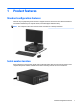
1 Product features Standard configuration features Features may vary depending on the model. For support assistance and to learn more about the hardware and software installed on your computer model, run the HP Support Assistant utility. NOTE: This computer model can be used in a tower orientation or a desktop orientation. Serial number location Each computer has a unique serial number and a product ID number that are located on the exterior of the computer.
Front panel components Drive configuration may vary by model. Some models have a bezel blank covering the slim optical drive bay. 1 Slim Optical Drive (optional) 5 Headphone Connector 2 SD Card Reader (optional) 6 Hard Drive Activity Light 3 USB 3.0 Ports (blue) 7 Dual-State Power Button 4 Microphone Connector NOTE: The Power On Light is normally white when the power is on. If it is flashing red, there is a problem with the computer and it is displaying a diagnostic code.
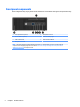
Rear panel components 1 PS/2 Mouse Connector (green) 6 VGA Monitor Connector 2 Serial Connector 7 USB 2.0 Ports (black) 3 RJ-45 Network Connector 8 DisplayPort Monitor Connector 4 Line-In Audio Connector (blue) 9 USB 3.0 Ports (blue) 5 PS/2 Keyboard Connector (purple) 10 Line-Out Connector for powered audio devices (green) 11 Power Cord Connector NOTE: An optional second serial port and an optional parallel port are available from HP.
2 Illustrated parts catalog Computer major components This chapter provides part information for all chassis. Item Description (1) System board (includes replacement thermal material) (2) Front bezel (3) Access panel (4) Power supply, 180W, Energy Star 6.
Item Description Intel Core i7 6700 (3.4-GHz, 8-MB L3 cache), 65W Intel Core i5 6600 (3.3-GHz, 6-MB L3 cache), 65W Intel Core i5 6500 (3.2-GHz, 6-MB L3 cache), 65W Intel Core i3 6320 (3.9-GHz, 4-MB L3 cache), 65W Intel Core i3 6300 (3.8-GHz, 4-MB L3 cache), 65W Intel Core i3 6100 (3.7-GHz, 3-MB L3 cache), 65W Intel Pentium G4520 (3.6-GHz, 3-MB L3 cache), 65W Intel Pentium G4500 (3.5-GHz, 3-MB L3 cache), 65W Intel Pentium G4400 (3.3-GHz, 3-MB L3 cache), 65W Intel Celeron G3920 (2.
Misc parts Item Description (1) Fan (2) Front I/O assembly (3) Fan sink (includes replacement thermal material) (4) SATA data cable, 150 mm, 2 straight ends (5) SATA data cable, 200 mm, 2 straight ends (6) Speaker (7) Power switch assembly (8) Printer port, PCI card (9) GeForce GT 730 graphics card, 2 GB, DDR3, PCIe x8 Nvidia NVS 310 graphics card, 512 MB, DDR3, PCIe x16 (not illustrated) * WLAN modules Intel 802.11 a/b/g/n (2x2) + Bluetooth 4.
Item Description * WLAN module adapter, PCIe card * Intel PRO/1000 single port GbE NIC, includes bracket * Card reader, 14-in-1, USB 2.
Drives Item Description (1) Hard drive 2 TB, 7200 rpm, 3.5 inch 1 TB, 7200 rpm, 3.5 inch 1 TB hard drive, hybrid SSD 500 GB, 7200 rpm, 3.5 inch 500 GB, 7200 rpm, 2.5 inch, self-encrypting (SED) 500 GB, 5400 rpm, 2.5 inch, FIPS 500 GB hard drive, hybrid SSD 512-GB Solid-state Drive (SSD), 3D, NAND 256-GB Solid-state Drive (SSD), 3D, NAND 256-GB Solid-state Drive (SSD), self-encrypting (SED) 256-GB Solid-state Drive (SSD) 180-GB Solid-state Drive (SSD) 180-GB Solid-state Drive (SSD), MLC, OPAL2.
3 Routine care, SATA drive guidelines, and disassembly preparation This chapter provides general service information for the computer. Adherence to the procedures and precautions described in this chapter is essential for proper service. CAUTION: When the computer is plugged into an AC power source, voltage is always applied to the system board. You must disconnect the power cord from the power source before opening the computer to prevent system board or component damage.
Generating static The following table shows that: ● Different activities generate different amounts of static electricity. ● Static electricity increases as humidity decreases.
● Heel straps/Toe straps/Boot straps can be used at standing workstations and are compatible with most types of shoes or boots. On conductive floors or dissipative floor mats, use them on both feet with a maximum of one-megohm ± 10% resistance between the operator and ground.
● Transparent metallized shielding bags ● Transparent shielding tubes Operating guidelines To prevent overheating and to help prolong the life of the computer: ● Keep the computer away from excessive moisture, direct sunlight, and extremes of heat and cold. ● Operate the computer on a sturdy, level surface. Leave a 10.2-cm (4-inch) clearance on all vented sides of the computer and above the monitor to permit the required airflow.
To clean the computer case, follow the procedures described below: ● To remove light stains or dirt, use plain water with a clean, lint-free cloth or swab. ● For stronger stains, use a mild dishwashing liquid diluted with water. Rinse well by wiping it with a cloth or swab dampened with clear water. ● For stubborn stains, use isopropyl (rubbing) alcohol. No rinsing is needed as the alcohol will evaporate quickly and not leave a residue.
Service considerations Listed below are some of the considerations that you should keep in mind during the disassembly and assembly of the computer. Power supply fan The power supply fan is a variable-speed fan based on the temperature in the power supply. CAUTION: The cooling fan is always on when the computer is in the “On” mode. The cooling fan is off when the computer is in “Standby,” “Suspend,” or “Off” modes.
● If a drive must be mailed, place the drive in a bubble-pack mailer or other suitable protective packaging and label the package “Fragile: Handle With Care.” ● Do not remove hard drives from the shipping package for storage. Keep hard drives in their protective packaging until they are actually mounted in the CPU. ● Avoid dropping drives from any height onto any surface. ● If you are inserting or removing a hard drive, turn off the computer.
SATA hard drive cables SATA data cable Always use an HP approved SATA 6.0 Gb/s cable as it is fully backwards compatible with the SATA 1.5 Gb/s drives. Current HP desktop products ship with SATA 6.0 Gb/s hard drives. SATA data cables are susceptible to damage if overflexed. Never crease a SATA data cable and never bend it tighter than a 30 mm (1.18 in) radius. The SATA data cable is a thin, 7-pin cable designed to transmit data for only a single drive.
4 Removal and replacement procedures: Small Form Factor Adherence to the procedures and precautions described in this chapter is essential for proper service. After completing all necessary removal and replacement procedures, run the Diagnostics utility to verify that all components operate properly. NOTE: Not all features listed in this guide are available on all computers.
Access panel 1. Prepare the computer for disassembly (Preparation for disassembly on page 17). 2. Loosen the thumbscrew on the rear of the computer (1) then slide the panel back (2) and lift if off the computer (3). To install the access panel, reverse the removal procedure. Front bezel 1. Prepare the computer for disassembly (Preparation for disassembly on page 17). 2. Remove the access panel (Access panel on page 18). 3.
Slim optical drive bezel blank On some models, there is a bezel blank covering the slim optical drive bay that needs to be removed before installing an optical drive. To remove a bezel blank: 1. Remove the access panel (Access panel on page 18). 2. Remove the front bezel (Front bezel on page 18). 3. To remove a slim optical drive bezel blank, press inward on the two retaining tabs (1) and pull the blank off the front bezel (2).
Expansion card Description Printer port, PCI card GeForce GT 730 graphics card, 2 GB, DDR3, PCIe x8 Nvidia NVS 310 graphics card, 512 MB, DDR3, PCIe x16 Intel 802.11 a/b/g/n (2x2) + Bluetooth 4.0 Wireless NIC Intel Dual Band Wireless 7265NV 802.11 a/b/g/n (2x2) Wireless NIC Intel Dual Band Wireless 7265AN 802.
5. Before installing an expansion card, remove the expansion slot cover or the existing expansion card. NOTE: Before removing an installed expansion card, disconnect any cables that may be attached to the expansion card. a. If you are installing an expansion card in a vacant PCI Express x16 socket, remove the appropriate expansion slot cover on the back of the chassis. Pull the slot cover straight up then away from the inside of the chassis. b.
c. If you are removing a PCI Express x1 card, hold the card at each end, and carefully rock it back and forth until the connectors pull free from the socket. Pull the expansion card straight up from the socket. d. If you are removing a PCI Express x16 card, pull the retention arm on the back of the expansion socket away from the card and carefully rock the card back and forth until the connectors pull free from the socket. Pull the expansion card straight up from the socket. 6.
8. To install a new expansion card, hold the card just above the expansion socket on the system board then move the card toward the rear of the chassis (1) so that the bracket on the card is aligned with the open slot on the rear of the chassis. Press the card straight down into the expansion socket on the system board (2). NOTE: When installing an expansion card, press firmly on the card so that the whole connector seats properly in the expansion card socket. 9.
Drive cage You can remove the drive cage from the computer. You must remove the optical drive to remove the drive cage. Remove the hard drive from the cage after removing the drive cage. 1. Prepare the computer for disassembly (Preparation for disassembly on page 17). 2. Remove the optical drive from the drive cage: 3. 24 a. Disconnect the power cable (1) and data cable (2) from the rear of the optical drive. b. Press the release lever on the back of the drive (3). c.
4. Press inward on the drive cage release latch (1), rotate the drive cage up (2), and then slide the tabs on the side of the drive cage out of the chassis (3). To install the drive cage, reverse the removal procedure.
Memory Description 16-GB, PC4-17000 8-GB, PC4-17000 4-GB, PC4-17000 The computer comes with double data rate 4 synchronous dynamic random access memory (DDR4-SDRAM) dual inline memory modules (DIMMs). DIMMs The memory sockets on the system board can be populated with up to two industry-standard DIMMs. These memory sockets are populated with at least one preinstalled DIMM.
● The system will operate in single channel mode if the DIMM sockets are populated in one channel only. ● The system will operate in a higher-performing dual channel mode if the memory capacity of the DIMM in Channel A is equal to the memory capacity of the DIMM in Channel B. ● The system will operate in flex mode if the memory capacity of the DIMM in Channel A is not equal to the memory capacity of the DIMM in Channel B.
5. To install a memory module, open both latches of the memory module socket (1), and insert the memory module into the socket (2). NOTE: A memory module can be installed in only one way. Match the notch on the module with the tab on the memory socket. For maximum performance, populate the sockets so that the memory capacity is spread as equally as possible between Channel A and Channel B. 6. Push the module down into the socket, ensuring that the module is fully inserted and properly seated.
System board connections Refer to the following illustration and table to identify the system board connectors for your model. No. System Board Connector System Board Label Color Component 1 PCI Express x16 X16PCIEXP black Expansion Card 2 PCI Express x1 X1PCIEXP1 black Expansion Card 3 DIMM3 (Channel A) DIMM3 black Memory Module 4 DIMM1 (Channel B) DIMM1 black Memory Module 5 Battery BAT black Memory Module 6 SATA 3.0 SATA1 light blue Optical Drive 7 SATA 3.
Drives Hard drive 2 TB, 7200 rpm, 3.5 inch 1 TB, 7200 rpm, 3.5 inch 1 TB hard drive, hybrid SSD 500 GB, 7200 rpm, 3.5 inch 500 GB, 7200 rpm, 2.5 inch, self-encrypting (SED) 500 GB, 5400 rpm, 2.5 inch, FIPS 500 GB hard drive, hybrid SSD 512-GB Solid-state Drive (SSD), 3D, NAND 256-GB Solid-state Drive (SSD), 3D, NAND 256-GB Solid-state Drive (SSD), self-encrypting (SED) 256-GB Solid-state Drive (SSD) 180-GB Solid-state Drive (SSD) 180-GB Solid-state Drive (SSD), MLC, OPAL2.
CAUTION: To prevent loss of work and damage to the computer or drive: If you are inserting or removing a drive, shut down the operating system properly, turn off the computer, and unplug the power cord. Do not remove a drive while the computer is on or in standby mode. Before handling a drive, ensure that you are discharged of static electricity. While handling a drive, avoid touching the connector. Handle a drive carefully; do not drop it. Do not use excessive force when inserting a drive.
3. Disconnect the power cable (1) and data cable (2) from the rear of the optical drive. Press the release lever on the back of the drive (3), and then slide the drive out of the front of the chassis (4). CAUTION: When removing the cables, pull the tab or connector instead of the cable itself to avoid damaging the cable. Installing a 9.5mm slim optical drive 32 1. Prepare the computer for disassembly (Preparation for disassembly on page 17). 2. Remove the access panel (Access panel on page 18). 3.
6. Slide the optical drive through the front bezel all the way into the bay (1) so that it locks in place (2), and then connect the power cable (3) and data cable (4) to the rear of the drive. 7. Connect the opposite end of the data cable to the light blue SATA connector on the system board labeled SATA1. NOTE: Refer to System board connections on page 29 for an illustration of the system board drive connectors.
● 5. If you are removing a 2.5-inch hard drive, remove the four screws that secure the drive to the drive cage (1) to release the drive (2). Install the new drive in the drive cage. ● If you are installing a 3.5-inch hard drive, slide the drive in the drive cage (1) and secure the drive with four 6-32 standard screws (2). NOTE: The four screw holes for the 3.5-inch hard drive are stamped “A” on the top of the drive cage.
● If you are installing a 2.5-inch hard drive, place the drive in the drive cage (1) and secure the drive with four M3 metric screws (2). NOTE: The four screw holes for the 2.5-inch hard drive are stamped “B” on the top of the drive cage. 6. Lower the drive cage into place.
36 7. Connect the power cable (1) and data cable (2) to the rear of the hard drive, and route the cables through the retainer clip (3). 8. Slide the optical drive through the front bezel all the way into the bay (1) so that it locks in place (2), and then connect the power cable (3) and data cable (4) to the rear of the drive. 9. Reassemble the computer.
Fan The fan is attached to the rear of the chassis with two Phillips screws. 1. Prepare the computer for disassembly (Preparation for disassembly on page 17). 2. Remove the access panel (Access panel on page 18). 3. From the outside, rear of the chassis, remove the two Phillips screws that secure the fan to the chassis. 4. From inside the chassis, disconnect the fan cable from the system board connector labeled CHFAN (1). 5. Lift the fan out of the chassis (2).
Fan sink The fan sink is secured atop the processor with four captive Torx screws. The fan sink includes a heat sink and a fan. 1. Prepare the computer for disassembly (Preparation for disassembly on page 17). 2. Remove the access panel (Access panel on page 18). 3. Loosen the four captive Torx T15 screws (1) that secure the fan sink to the system board tray, and then disconnect the fan cable from the system board connector labeled CPUFAN (2).
Processor Description Intel Core i7 6700 (3.4-GHz, 8-MB L3 cache), 65W Intel Core i5 6600 (3.3-GHz, 6-MB L3 cache), 65W Intel Core i5 6500 (3.2-GHz, 6-MB L3 cache), 65W Intel Core i3 6320 (3.9-GHz, 4-MB L3 cache), 65W Intel Core i3 6300 (3.8-GHz, 4-MB L3 cache), 65W Intel Core i3 6100 (3.7-GHz, 3-MB L3 cache), 65W Intel Pentium G4520 (3.6-GHz, 3-MB L3 cache), 65W Intel Pentium G4500 (3.5-GHz, 3-MB L3 cache), 65W Intel Pentium G4400 (3.3-GHz, 3-MB L3 cache), 65W Intel Celeron G3920 (2.
Power supply WARNING! To reduce potential safety issues, only the power supply provided with the computer, a replacement power supply provided by HP, or a power supply purchased as an accessory from HP should be used with the computer. The power supply is located at the rear of the chassis. It is held in place by three Torx screws outside of the chassis. 40 1. Prepare the computer for disassembly (Preparation for disassembly on page 17). 2. Remove the access panel (Access panel on page 18). 3.
7. From the inside of the chassis, slide the power supply forward, and then lift it out of the chassis. To install the power supply, reverse the removal procedure. CAUTION: When installing the power supply cables, make sure they are properly positioned in the clip under the drive cage.
Front I/O assembly 1. Prepare the computer for disassembly (Preparation for disassembly on page 17). 2. Remove the access panel (Access panel on page 18). 3. Remove the front bezel (Front bezel on page 18). 4. Remove the drive cage (Drive cage on page 24). 5. Disconnect the cables from the system board as follows: (1): Blue connector labeled FRONT USB 3.0 (2): Blue connector labeled FRONT AUD 6. Remove the cables from the cable clips under the drive cage (3). 7.
Power switch assembly The power switch assembly is attached to the front of the chassis under the drive cage. 1. Prepare the computer for disassembly (Preparation for disassembly on page 17). 2. Remove the access panel (Access panel on page 18). 3. Remove the front bezel (Front bezel on page 18). 4. Remove the drive cage (Drive cage on page 24). 5. From inside the chassis, disconnect the cable from the system board connector labeled PB/LED (1). 6.
Speaker The speaker is attached to the front of the chassis under the drive cage. 1. Prepare the computer for disassembly (Preparation for disassembly on page 17). 2. Remove the access panel (Access panel on page 18). 3. Remove the front bezel (Front bezel on page 18). 4. Remove the drive cage (Drive cage on page 24). 5. From the outside, front of the chassis, remove the two Torx screws that secure the speaker to the chassis. 6. Disconnect the speaker cable from the system board labeled SPKR (1).
● Memory modules (Memory on page 26) ● Expansion cards (Expansion card on page 20) ● Fan sink (Fan sink on page 38) ● Processor (Processor on page 39) 4. Remove the drive cage (Drive cage on page 24). 5. Disconnect cables from the system board. 6. Remove the six Torx screws (1) that secure the system board to the chassis. 7. Slide the system board toward the front of the chassis to disengage the connectors (2). 8. Lift the system board up and out of the chassis (3).
System board callouts 46 Sys Bd Label Color Component Sys Bd Label Color Component XU1 Silver Processor SATA1 Light blue Any SATA Device other than the primary hard drive PWRCPU White 4-pin processor power SPKR White Speaker CPUFAN Red Processor fan SD RDR Black Card reader DIMM3 Black Memory module PSWD Green Clear system passwords DIMM1 Black Memory module X16PCIEXP Black Expansion card BAT Black RTC battery X1PCIEXP1 Black Expansion card PB/LED Black Power sw
Changing from desktop to tower configuration The Small Form Factor computer can be used in a tower orientation with an optional tower stand that can be purchased from HP. 1. Prepare the computer for disassembly (Preparation for disassembly on page 17). 2. Orient the computer so that its right side is facing down and place the computer in the optional stand. NOTE: To stabilize the computer in a tower orientation, HP recommends the use of the optional tower stand. 3.
5 Computer Setup (F10) Utility Computer Setup (F10) Utilities Use Computer Setup (F10) Utility to do the following: ● Change settings from the defaults or restore the settings to default values. ● View the system configuration, including settings for processor, graphics, memory, audio, storage, communications, and input devices. ● Modify the boot order of bootable devices such as hard drives, optical drives, or USB flash media devices.
4. Use the arrow (left and right) keys to select the appropriate heading. Use the arrow (up and down) keys to select the option you want, then press Enter. To return to the Computer Setup Utilities menu, press Esc. 5. To apply and save changes, select Main > Save Changes and Exit. ● If you have made changes that you do not want applied, select Ignore Changes and Exit. ● To restore settings from the Advanced and Main menus to original values, select Apply Factory Defaults and Exit.
Computer Setup–Main NOTE: Support for specific Computer Setup options may vary depending on the hardware configuration. Table 5-1 Computer Setup—Main Option Description System Information Lists all information in following list if Advanced System Information is selected. Lists smaller subset if Basic System Information is selected.
Table 5-1 Computer Setup—Main (continued) ● Lock BIOS Version If this option is checked, the system is locked to the current BIOS version and updates are not allowed. ● BIOS Update Preferences Allows the administrator to select the source of network updates (www.hp.
Computer Setup—Security NOTE: Support for specific Computer Setup options may vary depending on the hardware configuration. Table 5-2 Computer Setup—Security Option Description Set up BIOS Administrator Password Lets you set and enable a BIOS administrator password, which includes the following privileges: ● Manage other BIOS users ● Full access to BIOS policy and settings ● Unlock the computer when other BIOS users fail the preboot authentication.
Table 5-2 Computer Setup—Security (continued) ● Data Recovery Policy Select ‘Automatic’ or ‘Manual’ to set data recovery policy. ‘Manual’ lets you select whether or not to execute recovery of a corrupted region if it is detected. Set Up BIOS Power-On Password Lets you set and enable a BIOS power-on password. The power-on password prompt appears after a power cycle or reboot. If the user does not enter the correct power-on password, the unit will not boot.
Table 5-2 Computer Setup—Security (continued) Default is ‘Unlock’. Cover Removal Sensor (Disabled/Notify user/Administrator password) Lets you disable the cover sensor or configure what action is taken if the computer cover was removed. Default is ‘Disabled’. NOTE: Notify user alerts the user with a POST error on the first boot after the sensor detects removal of the cover.
Table 5-3 Computer Setup—Advanced (for advanced users) (continued) ● Legacy Boot Order Specify the order in which legacy boot sources (such as a network interface card, internal hard drive, USB optical drive, or internal optical drive) are checked for a bootable operating system image. Specify the order of attached hard drives. The first hard drive in the order will have priority in the boot sequence and will be recognized as drive C (if any devices are attached).
Table 5-3 Computer Setup—Advanced (for advanced users) (continued) Virtualization Technology for Directed I/O (VTd) (Intel only) Controls virtualization DMA remapping features of the chipset. Changing this setting requires turning the computer off and then back on. Default is disabled. PCI Express Slot x (enable/disable) Lets you disable individual expansion slots.
Table 5-3 Computer Setup—Advanced (for advanced users) (continued) ● Serial port B ● SATA0 ● SATA1 ● SATA2 ● SATA3 ● SATA5 ● Front USB ports ● Rear USB ports ● USB charging port function ● Media card reader Restrict USB Devices Specify the following categories of USB devices to enable: ● Allow all USB devices ● Allow only keyboard and mouse ● Allow all but storage devices and hubs.
Table 5-3 Computer Setup—Advanced (for advanced users) (continued) This feature is designed to provide a visual indication of what sleep state the system is in. Each sleep state has a unique blink pattern. Default is disabled. NOTE: A normal shutdown goes to the S4 state for Windows 8 or later. S0 (On) = Solid white LED. S3 (Stand By)= 3 blinks at 1Hz (50% duty cycle) followed by a pause of 2 seconds (white LED) — repeated cycles of 3 blinks and a pause.
Recovering the Configuration Settings This method of recovery requires that you first perform the Save to Removable Media command with the Computer Setup (F10) Utility before Restore is needed. (See Computer Setup–Main on page 50 in the Computer Setup—File table.) The Save to Removable Media option creates a file named HPSETUP.TXT on an inserted USB flash media device. This file can be edited to change the settings on Restore. An asterisk (*) marks the selected option for a setting.
6 Troubleshooting without diagnostics This chapter provides information on how to identify and correct minor problems, such as USB devices, hard drive, optical drive, graphics, audio, memory, and software problems. If you encounter problems with the computer, refer to the tables in this chapter for probable causes and recommended solutions.
If it becomes necessary to call for technical assistance, be prepared to do the following to ensure that your service call is handled properly: ● Be in front of your computer when you call. ● Write down the computer serial number, product ID number, and monitor serial number before calling. ● Spend time troubleshooting the problem with the service technician. ● Remove any hardware that was recently added to your system. ● Remove any software that was recently installed.
● If you have installed an operating system other than the factory-installed operating system, check to be sure that it is supported on the system. ● If the system has multiple video sources (embedded, PCI, or PCI-Express adapters) installed (embedded video on some models only) and a single monitor, the monitor must be plugged into the monitor connector on the source selected as the primary VGA adapter.
Computer date and time display is incorrect. Cause Solution RTC (real-time clock) battery may need to be replaced. Reset the date and time under Control Panel (Computer Setup can also be used to update the RTC date and time). If the problem persists, replace the RTC battery. See the Removal and Replacement section for instructions on installing a new battery, or contact an authorized dealer or reseller for RTC battery replacement.
Poor performance. Cause Solution 3. Make sure the processor heat sink is installed properly. Hard drive is full. Transfer data from the hard drive to create more space on the hard drive. Low on memory. Add more memory. Hard drive fragmented. Defragment hard drive. Program previously accessed did not release reserved memory back to the system. Restart the computer. Virus resident on the hard drive. Run virus protection program. Too many applications running. 1.
Computer powered off automatically and the Power LED flashes red four times and then white two times. Cause Solution Processor thermal protection activated: 1. Ensure that the computer air vents are not blocked and the processor cooling fan is running. 2. Open the access panel, press the power button, and see if the processor fan (or other system fan) spins. If the fan does not spin, make sure the fan cable is plugged onto the system board header. 3. If fan a plugged in and not spinning, replace it.
Solving power problems Common causes and solutions for power problems are listed in the following table. Power supply shuts down intermittently. Cause Solution If equipped with a voltage selector, voltage selector switch on rear of computer chassis (some models) not switched to correct line voltage (115V or 230V). Select the proper AC voltage using the selector switch. Power supply will not turn on because of internal power supply fault. Replace the power supply.
Solving hard drive problems Hard drive error occurs. Cause Solution Hard disk has bad sectors or has failed. 1. In Windows 7, click Start, click Computer, and right-click on a drive. Select Properties, and then select the Tools tab. Under Error-checking click Check Now. In Windows 8.1, on the Start screen type e, and then select File Explorer from the list of applications. In the left column, expand Computer, right-click on a drive, select Properties, and then select the Tools tab.
Drive not found (identified). Cause Solution The device is attached to a SATA port that has been hidden in Computer Setup. Run the Computer Setup utility and ensure Device Available is selected for the device's SATA port in Advanced > Port Options. Drive responds slowly immediately after power-up. Run Computer Setup and increase the POST Delay in Advanced > Boot Options. Nonsystem disk/NTLDR missing message.
Computer seems to be locked up. Cause Solution Program in use has stopped responding to commands. 1. Use the task manager to close programs that do not respond. 2. Attempt the normal Windows “Shut Down” procedure. If this fails, press the power button for four or more seconds to turn off the power. To restart the computer, press the power button again. Solving media card reader problems Media card will not work in a digital camera after formatting it in Windows.
Do not know how to remove a media card correctly. Cause Solution The computer’s software is used to safely eject the card. In Windows 7, click Start, select Computer, right-click on the corresponding drive icon, and then select Eject. Pull the card out of the slot. In Windows 8.1, on the Start screen, type e, and then click File Explorer from the list of applications. Expand Computer, rightclick on the corresponding drive icon, and then select Eject. Pull the card out of the slot.
Blank screen (no video). Cause Solution You may have a screen blanking utility installed or energy saver features are enabled. Press any key or click the mouse button and type your password (if set). System ROM is corrupted; system is running in Boot Block Emergency Recovery Mode (indicated by eight beeps). Reflash the system ROM with the latest BIOS image. You are using a fixed-sync monitor and it will not sync at the resolution chosen.
Blank screen and the power LED flashes Red six times, once every second, followed by a two second pause, and the computer beeps six times. (Beeps stop after fifth iteration but LEDs continue flashing.) Cause Solution Pre-video graphics error. For systems with a graphics card: 1. Reseat the graphics card (if applicable). Power on the system. 2. Replace the graphics card (if applicable). 3. Replace the system board. For systems with integrated graphics, replace the system board.
The picture is broken up, rolls, jitters, or flashes. Cause Solution The monitor connections may be incomplete or the monitor may be incorrectly adjusted. 1. Be sure the monitor cable is securely connected to the computer. 2. In a two-monitor system or if another monitor is in close proximity, be sure the monitors are not interfering with each other’s electromagnetic field by moving them apart. 3. Fluorescent lights or fans may be too close to the monitor. Monitor needs to be degaussed.
“Out of Range” displays on screen. Cause Solution 1. Press the Windows logo + l to open the Settings charm. 2. Select Change PC Settings, select General, and then under Advanced startup, click Restart now. 3. Select Troubleshoot, select Advanced options, select Startup Settings, and then click Restart. 4. Use the function keys or number keys to select the safe mode option you want. When your computer is in safe mode, Safe Mode displays in the corners of your monitor.
Certain typed symbols do not appear correct. Cause Solution In Windows 7, click Start, select All Programs, select Accessories, select System Tools, and then select Character Map. In Windows 8.1, on the Start screen, type ch, and then select Character Map from the list of applications. In Windows 10, type ch in the taskbar search box, and then select Character Map from the list of applications.
Sound does not come out of the speaker or headphones. Cause Solution The application is set to use a different audio device than speakers. Some graphics cards support audio over the DisplayPort connection (if applicable), so multiple audio devices may be listed in Device Manager. Make sure the correct device is being used. To access Device Manager in Windows 7, click Start, select Control Panel, and then select Device Manager. To access Device Manager in Windows 8.
There is no sound or sound volume is too low. Cause Solution To access Device Manager in Windows 8.1, from the Start screen, type c, select Control Panel from the list of applications, and then select Device Manager. To access Device Manager in Windows 10, type device manager in the taskbar search box, and then select Device Manager from the list of applications. Some applications can select which audio output device is used. Make sure the application has selected the correct audio device.
Printer prints garbled information. Cause Solution The cables may not be connected properly. Reconnect all cables. Printer memory may be overloaded. Reset the printer by turning it off for one minute, then turn it back on. Printer will not print. Cause Solution The printer may be out of paper. Check the paper tray and refill it if it is empty.
Mouse does not respond to movement or is too slow. Cause Solution 1. Press the Ctrl and Esc keys at the same time (or press the Windows logo key) to display the Start menu. 2. Use the arrow keys to select Shut Down and then press Enter. 3. After the shutdown is complete, plug the mouse connector into the back of the computer (or the keyboard) and restart. Windows 8.1: 1. Press the Windows logo + l to open the Settings charm. 2. Use the arrow keys to select Power, and then press Enter. 3.
Solving Hardware Installation Problems You may need to reconfigure the computer when you add or remove hardware, such as an additional drive or expansion card. If you install a plug and play device, Windows automatically recognizes the device and configures the computer. If you install a non-plug and play device, you must reconfigure the computer after completing installation of the new hardware. In Windows, use the Add Hardware Wizard and follow the instructions that appear on the screen.
Computer will not start. Cause Solution NOTE: DIMM1 or XMM1 must always be installed. DIMM1 must be installed before DIMM2, and DIMM3 must be installed before DIMM4. 2. Observe the beeps and LED lights on the front of the computer. Beeps and flashing LEDs are codes for specific problems. 3. If you still cannot resolve the issue, contact Customer Support. Power LED flashes Red three times and then white two times. Cause Solution Memory is installed incorrectly or is bad.
Table 6-2 Solving Network Problems (continued) Network driver does not detect network controller. Cause Solution To access Device Manager in Windows 10, type device manager in the taskbar search box, and then select Device Manager from the list of applications. Incorrect network driver. Check the network controller documentation for the correct driver or obtain the latest driver from the manufacturer’s Web site. Network status link light never flashes.
Diagnostics reports a failure. Cause Solution The cable is not securely connected. Ensure that the cable is securely attached to the network connector and that the other end of the cable is securely attached to the correct device. The cable is attached to the incorrect connector. Ensure that the cable is attached to the correct connector. There is a problem with the cable or a device at the other end of the cable. Ensure that the cable and device at the other end are operating correctly.
New network card will not boot. Cause Solution New network card may be defective or may not meet industrystandard specifications. Install a working, industry-standard NIC, or change the boot sequence to boot from another source. Cannot connect to network server when attempting Remote System Installation. Cause Solution The network controller is not configured properly.
Out of memory error. Cause Solution You have run out of memory to run the application. Check the application documentation to determine the memory requirements. Memory count during POST is wrong. Cause Solution The memory modules may not be installed correctly. Check that the memory modules have been installed correctly and that proper modules are used. Integrated graphics may use system memory. No action required. Insufficient memory error during operation.
System will not boot from CD-ROM or DVD drive. Cause Solution Non-bootable CD in drive. Try a bootable CD in the drive. Boot order not correct. Run the Computer Setup utility and change boot sequence in Advanced > Boot Options. Drive not found (identified). Cause Solution Cable could be loose. Check cable connections. The system may not have automatically recognized a newly installed device. See reconfiguration directions in the Solving Hardware Installation Problems on page 80 section.
Cannot eject compact disc (tray-load unit). Cause Solution Disc not properly seated in the drive. Turn off the computer and insert a thin metal rod into the emergency eject hole and push firmly. Slowly pull the tray out from the drive until the tray is fully extended, then remove the disc. CD-ROM, CD-RW, DVD-ROM, or DVD-R/RW drive cannot read a disc or takes too long to start. Cause Solution Media is corrupt. Try different media to confirm whether media is valid. Media has been inserted upside down.
Solving USB flash drive problems If you encounter USB flash drive problems, common causes and solutions are listed in the following table. USB flash drive is not seen as a drive letter in Windows. Cause Solution The drive letter after the last physical drive is not available. Change the default drive letter for the flash drive in Windows. USB flash drive not found (identified). Cause Solution The device is attached to a USB port that has been hidden in Computer Setup.
Solving front panel component problems If you encounter problems with devices connected to the front panel, refer to the common causes and solutions listed in the following table. A USB device, headphone, or microphone is not recognized by the computer. Cause Solution Device is not properly connected. 1. Turn off the computer. 2. Reconnect the device to the front of the computer and restart the computer. The device does not have power.
Unable to connect to the Internet. Cause Solution 3. In the Browsing history section on the General tab, click the Delete button. 4. Select the Cookies check box and click the Delete button. Windows 8.1: 1. From the Start screen, type c, and then select Control Panel from the list of applications. 2. Click Internet Options. 3. In the Browsing history section on the General tab, click the Delete button. 4. Select the Cookies check box and click the Delete button. Windows 10: 1.
Solving software problems Most software problems occur as a result of the following: ● The application was not installed or configured correctly. ● There is insufficient memory available to run the application. ● There is a conflict between applications. ● Be sure that all the needed device drivers have been installed. ● If you have installed an operating system other than the factory-installed operating system, check to be sure it is supported on the system.
7 POST error messages and diagnostic front panel LEDs and audible codes This appendix lists the error codes, error messages, and the various indicator light and audible sequences that you may encounter during Power-On Self-Test (POST) or computer restart, the probable source of the problem, and steps you can take to resolve the error condition. POST Message Disabled suppresses most system messages during POST, such as memory count and nonerror text messages.
Control panel message 008–Microcode Patch Error 009–PMM Allocation Error during MEBx Download Description Recommended action RTC (real-time clock) battery may need to be replaced. problem persists, replace the RTC battery. See the Removal and Replacement section for instructions on installing a new battery. Processor is not supported by the BIOS. 1. Upgrade BIOS to proper version. 2. Change the processor. 1. Reboot the computer. 2.
Control panel message Description Recommended action 00E-Inventory Error during MEBx Execution BIOS information passed to the MEBx resulted in a failure. 1. Reboot the computer. 2. If the error persists, update to the latest BIOS version. 3. If the error still persists, replace the system board. 1. Reboot the computer. 2. If the error persists, update to the latest BIOS version. 3. If the error still persists, replace the system board.
Control panel message 302-Hard Disk 2: SMART Hard Drive Detects Imminent Failure 309 – 30C: Hard Disk 3–6: SMART Hard Drive Detects Imminent Failure Description Recommended action Hard drive is about to fail. (Some hard drives have a hard drive firmware patch that will fix an erroneous error message.) Hard drive is about to fail. (Some hard drives have a hard drive firmware patch that will fix an erroneous error message.) 3. Back up contents and replace hard drive. 1.
Control panel message Description 3. Reconfigure card resources and/or run Computer Setup or Windows utilities. If a PCI expansion card was recently added, remove it to see if the problem remains. 419-Out of Memory Space for Option ROMs Recently added PCI expansion card contains an option ROM too large to download during POST. ▲ 41A-Front USB1/USB2 Not Connected Front USB cable has been detached or unseated from system board. Reconnect or replace front USB cable.
Control panel message Description Recommended action 90B-Fan Failure The system has detected that a cooling fan is not operating correctly. 1. Reseat fan. 2. Reseat fan cable. 3. Replace fan. 90D-System Temperature Thermal shutdown occurred. The system BIOS has detected your machine was previously shut down to avoid overheating. Overheating may occur if the cooling vents are blocked or the operating temperature exceeds the system specifications.
4 Thermal 5 System board Patterns of blink/beep codes are determined by using the following parameters: ● 1 second pause occurs after the last major blink. ● 2 second pause occurs after the last minor blink. ● Beep error code sequences occur for the first 5 iterations of the pattern and then stop. ● Blink error code sequences continue until the computer is unplugged or the power button is pressed. NOTE: Not all diagnostic lights and audible codes are available on all models.
8 Password security and resetting CMOS This computer supports security password features, which can be established through the Computer Setup Utilities menu. This computer supports two security password features that are established through the Computer Setup Utilities menu: administrator password and power-on password. When you establish only an administrator password, any user can access all the information on the computer except Computer Setup.
1. Shut down the operating system properly, then turn off the computer and any external devices, and disconnect the power cord from the power outlet. 2. With the power cord disconnected, press the power button again to drain the system of any residual power. WARNING! To reduce the risk of personal injury from electrical shock and/or hot surfaces, be sure to disconnect the power cord from the wall outlet, and allow the internal system components to cool before touching.
Clearing and resetting the BIOS The CMOS button resets BIOS settings to default, but does not clear the passwords or affect any of the other Security settings. On Intel systems with advanced manageability features, the CMOS button will also partially unprovision AMT. 1. Turn off the computer and any external devices, and disconnect the power cord from the power outlet. 2. Disconnect the keyboard, monitor, and any other external equipment connected to the computer.
9 Using HP PC Hardware Diagnostics (UEFI) HP PC Hardware Diagnostics is a Unified Extensible Firmware Interface (UEFI) that allows you to run diagnostic tests to determine whether the computer hardware is functioning properly. The tool runs outside the operating system so that it can isolate hardware failures from issues that are caused by the operating system or other software components.
4. Select your computer, and then select your operating system. 5. In the Diagnostic section, follow the on-screen instructions to select and download the UEFI version you want.
10 System backup and recovery Backing up, restoring, and recovering in Windows 8.1 or Windows 8 Your computer includes tools provided by HP and Windows to help you safeguard your information and retrieve it if you ever need to. These tools will help you return your computer to a proper working state or even back to the original factory state, all with simple steps.
Using Reset when the system is not responding NOTE: You may be prompted by User Account Control for your permission or password when you perform certain tasks. To continue a task, select the appropriate option. For information about User Account Control, see Help and Support. From the Start screen, type help, and then select Help and Support. IMPORTANT: Reset does not provide backups of your information. Before using Reset, back up any personal information you wish to retain.
Recovery using Windows operating system media (purchased separately) To order a Windows operating system DVD, contact support. Go to http://www.hp.com/support, select your country or region, and follow the on-screen instructions. CAUTION: Using Windows operating system media completely erases the hard drive contents and reformats the hard drive. All files that you have created and any software that you have installed on the computer are permanently removed.
1. After you successfully set up the computer, create recovery media. This media can be used to reinstall the original operating system in cases where the hard drive is corrupted or has been replaced. See Creating recovery media on page 107. 2. As you add hardware and software programs, create system restore points. A system restore point is a snapshot of certain hard drive contents saved by Windows System Restore at a specific time.
NOTE: Do not use media cards for creating recovery media. The system may not be able to boot up from a media card and you may not be able to run system recovery. To create recovery discs: 1. Close all open programs. 2. Click the Start button, click All Programs, click Security and Protection, click Recovery Manager, and then click HP Recovery Media Creation. If prompted, click Yes to allow the program to continue. 3. Click Create recovery media using blank DVD(s), and then click Next. 4.
1. Select Start > All Programs > Productivity and Tools > HP Recovery Disc Creator. 2. Select Windows disk. 3. From the drop-down menu, select the drive for burning the recovery media. 4. Click the Create button to start the burning process. Label the disc after you create it, and store it in a secure place. After the Windows 7 operating system DVD has been created, create the Driver Recovery DVD: 1. Select Start > All Programs > Productivity and Tools > HP Recovery Disc Creator. 2.
1. Close all open programs. 2. Click the Start button, right-click Computer, and then click Properties. 3. Click System protection, System Restore, click Next, and then follow the on-screen instructions. System Recovery WARNING! This procedure will delete all user information. To prevent loss of information, be sure to back up all user information so you can restore it after recovery.
6. Under I need help immediately, click System Recovery. 7. Select Yes, and then click Next. Your computer restarts. 8. When the computer restarts, you will see the Recovery Manager welcome screen again. Under I need help immediately, click System Recovery. If you are prompted to back up your files, and you have not done so, select Back up your files first (recommended), and then click Next. Otherwise, select Recover without backing up your files, and then click Next. 9. System Recovery begins.
6. If Recovery Manager asks if you want to run System Recovery from Media or Hard Drive, select Media. On the Welcome screen, under I need help immediately, click Factory Reset. 7. If you are prompted to back up your files, and you have not done so, select Back up your files first (recommended), and then click Next. Otherwise, select Recover without backing up your files, and then click Next. 8. If you are prompted to insert the next recovery disc, do so. 9.
After the repair is completed: 1. Eject the Windows 7 operating system DVD and then insert the Driver Recovery DVD. 2. Follow the on-screen instructions to install the Hardware Enabling Drivers first, and then install Recommended Applications.
A Battery replacement The battery that comes with the computer provides power to the real-time clock. When replacing the battery, use a battery equivalent to the battery originally installed in the computer. The computer comes with a 3-volt lithium coin cell battery. WARNING! The computer contains an internal lithium manganese dioxide battery. There is a risk of fire and burns if the battery is not handled properly. To reduce the risk of personal injury: Do not attempt to recharge the battery.
b. Slide the replacement battery into position, positive side up. The battery holder automatically secures the battery in the proper position. Type 2 a. To release the battery from its holder, squeeze the metal clamp that extends above one edge of the battery. When the battery pops up, lift it out (1). b. To insert the new battery, slide one edge of the replacement battery under the holder’s lip with the positive side up.
b. Insert the new battery and position the clip back into place. NOTE: After the battery has been replaced, use the following steps to complete this procedure. 8. Replace the access panel. 9. Plug in the computer and turn on power to the computer. 10. Reset the date and time, your passwords, and any special system setups using Computer Setup. 11. Lock any security devices that were disengaged when the access panel was removed.
B Statement of Volatility HP confirms that Intel-based business desktop systems contain DDR4 volatile memory (memory amount depends on the customer configuration).
C Power cord set requirements The power supplies on some computers have external power switches. The voltage select switch feature on the computer permits it to operate from any line voltage between 100-120 or 220-240 volts AC. Power supplies on those computers that do not have external power switches are equipped with internal switches that sense the incoming voltage and automatically switch to the proper voltage.
Country-specific requirements Additional requirements specific to a country are shown in parentheses and explained below. Country Accrediting Agency Country Accrediting Agency Australia (1) EANSW Italy (1) IMQ Austria (1) OVE Japan (3) METI Belgium (1) CEBC Norway (1) NEMKO Canada (2) CSA Sweden (1) SEMKO Denmark (1) DEMKO Switzerland (1) SEV Finland (1) SETI United Kingdom (1) BSI France (1) UTE United States (2) UL Germany (1) VDE 1.
D Specifications Chassis (in the desktop position) Height 3.7 in 95 mm Width 10.6 in 270 mm Depth 11.8 in 300 mm Approximate Weight 9.8 lb 4.43 kg Weight Supported (maximum distributed load in desktop position) 77 lb 35 kg Operating 50° to 95°F 10° to 35°C Nonoperating -22° to 140°F -30° to 60°C Temperature Range NOTE: Operating temperature is derated 1.0° C per 300 m (1000 ft) to 3000 m (10,000 ft) above sea level; no direct sustained sunlight. Maximum rate of change is 10° C/Hr.
Index A access panel illustrated 4 locked 63 removal and replacement 18 administrator password 99 audible codes 97 audio problems 75 computer specifications 120 computer cleaning 12 Computer Setup access problem 62 country power cord set requirements 119 Customer Support 60 B backup and recovery, Windows 7 106 Backup and Restore, Windows 7 109 backups creating Windows 7 107, 109 battery disposal 15 battery replacement 114 beep codes 97 BIOS clearing and resetting 101 booting options Full Boot 92 Quick Boo
Internet access problems 89 K keyboard cleaning 13 keyboard problems 78 M media card reader problems 69 memory installation 26 problems 84 socket population 26 specifications 26 monitor problems 70 mouse cleaning 13 problems 78 N network problems 81 numeric error codes 92 O operating guidelines 12 operating system media, Windows 8 106 operating system media, Windows 8.
removal and replacement 44 SATA connectors 15 system board connections 29 System Recovery using Windows 7 recovery media 111 System Recovery, Windows 7 110 system restore points, creating Windows 7 107 System Restore, Windows 7 109 T tamper-proof screws tool 14 temperature control 12 tools, servicing 14 Torx T15 screwdriver 14 tower conversion 47 V ventilation, proper Driver Recovery media 106 f11 recovery 104 hard drive recovery 104 operating system DVD 106 recovery partition 104 restoring the hard drive